
RadiantD°wndraftC°°kt°pI JENN-AIR01
ModelJED8430 403WESTFOURTHSTREETNORTH.NEWTONA_020
INSTALLER - SAVE FOR THE LOCAL ELECTRICAL INSPECTOR'S USE.
Installation should be performed only by an authorized Jenn-Air Service Contractor or other qualified installer.
Read Safety Precautions in the Use & Care Manual before using this appliance,
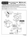
INSTRUCTIONS TO INSTALLER: Side Clearance - Unit may be safely installed as near as O" (0 cm) from a side wall
if space limitations requires. However, a side clearance of at least 6" (15.24 cm) is recommended for optimum ventilation.
NOTICE TO INSTALLER: Leave these instructions with the appliance.
NOTICE TO CONSUMER: Retain these instructions for future reference.
29 3/4 o
[75.27 cm]
22"
[55.88 cm]
28 7/8" _1/16 •
[73.05cm_.16 cm]
21 1/8" ±1/8"
[53.66cm±.32 cm]
10"
[25.40 cm] 44
CUTOUT
DIMENSIONS
SELECT APPROPRIATE
DUCT CUTOUT.
BLOWER MAY BE ROTATED
FOR HORIZONTAL OR
VERTICAL DIRECTION BY
LOOSENING NUTS AROUND
THE BLOWER INLET.
(SEE DUCTING INSTRUCTIONS,)
29 3/4 °
l € 5/8"
11.75cm
Min. Cleoronce l
Required
17 1/2 °
[44.46 cm]
1
2"[5.08 an] MIN_
MINIMUM CABINET
TO MOTOR CLEARANCE
FOR COOLING PURPOSE.
[75.27 cm]
LJ
12 1/2"
[31.76 cm]
1/2o._..,=
[31.75cm]
8101 P419-60
(01-03-01)

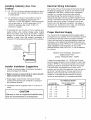
Installing Cabinetry Over Your
Cooktop
A = 30" (76.2 cm) minimum clearance between the top of
the cooktop and the bottom of an unprotected wood
or metal cabinet.
A = 24" (60.96 cm) minimum when bottom of wood or
metal cabinet is protected by not less than 1/4"
(0.635 cm). FLAME RETARDANT millboard covered
with not less than no. 28 MSG sheet steel, 0.015"
(0.038 cm) stainless steel, 0.024" (0.061 cm)
aluminum or copper.
* To eliminate the risk of burns or fire by reaching over
heated surface units, cabinet storage space located
above the surface units should be avoided. If cabinet
storage is to be provided, the risk can be reduced by
installing a range hood that projects horizontally a
minimum of 5 inches beyond the bottom of the cabinets.
DOTTED LINES
INDICATE
RANGE HOOD
CONSTRUCTION.._
t ....
A _
I
k__--._-._
Installer Installation Suggestions
1. Chamfer all exposed edges of decorative laminate to
prevent damage from chipping.
2. Radius corners of cutout and file to insure smooth
edges and prevent corner cracking,
3. Rough edges, inside corners which have not been
rounded and forced fits can contribute to cracking of
the countertop laminate.
4. Countertop must be supported within 3" (7.62 cm) of
cutout.
CAUTION
warranty is Void on equipment installed other
than as recommended by manUfacturer! I
Electrical Wiring Information
The neutral of this unit is grounded to the frame through
the green grounding wire. If used on new branch-circuit
installations (1996 NEC), mobile homes, recreational
vehicles, or in an area where local codes prohibit
grounding through the neutral conductor, untwist or
disconnect the green wire and connect the green wire to
ground in accordance with local code. Connect the white
neutral to the service neutral. Connect all wires to the
branch circuit with approved connectors. Use copper or
aluminum wire. If aluminum wire is used, use connectors
recognized for joining aluminum to copper.
Proper Electrical Supply
You must provide an adequate electrical supply system
as required for your cooktop. All wire connections must be
in accordance with local codes and properly insulated.
Check with local utility for governing electrical codes and
ordinances. In the absence of local electrical codes, the
National Electrical Code, NFPA No. 70, governing electric
range installations must be followed. A copy of the
National Electrical Code, NFPA No. 70, can be obtained
by writing to:
National Fire Protection Association
Batterymarch Park
Quincy, Massachusetts 02269
A three-wire, single phase, A.C. 120/240 volt 60 cycle
electrical system (properly circuit protected to meet Local
Codes of NFPA No. 70) must be provided. Unit must be
properly grounded in accordance with local wiring code.
The chart below recommends the minimum circuit
protector and wire size if the appliance is the only unit on
the circuit. If smaller sizes of wire are used, the unit
efficiency will be reduced and a fire hazard may be
created. It is advisable that the electrical wiring and
hookup be accomplished by a competent electrician.
RECOMMENDED MINIMUM
K.W. RATING CIRCUIT PROTECTION WIRE SIZE
ON SERIAL PLATE IN AMPERS (AWG)
0- 4.9 20 12
5.0- 6.9 30 10
7.0 - 9.9 40 8
10.0 - 11.9 50 8
12.0 - 14.9 60 6

Notice To Installer
Follow accompanying instructions carefully.
This appliance is designed to always be vented outdoors.
This appliance should be ducted separately from other
vented appliances.
Never use a metal blade tOpry knob off, If knob
cannot be easily removed, tuck folds of a
dishtowel under knob skirt and pu!f upward with
steady, even pressure.
Installation Of Appliance
1. Unpack unit.
2. Provide cutout for countertop and duct opening as
required per page 1.
3. Place unit in the cutout.
4. Loosen cap nuts inside plenum to rotate blower
housing to desired position. Connect outlet blower
housing to vent duct. Tighten cap nuts inside plenum.
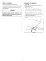
5. Remove attachment screw and cover from junction
box. Connect BX cable to knockout on side of the
junction box. Make wire connections, push wires into
junction box. Re-attach cover. Consult local codes for
proper power hookup (figure 1).
6. Test to insure control knobs operate all elements
properly.
N BOX
BX CABLE""_""_ _ RIGHT CENTER
FIGURE 1

ZJENN-AIR!
403WESTFOURTHSTREET,NORTH• NEWTON,IA50208
-
 1
1
-
 2
2
-
 3
3
-
 4
4


Jenn-Air CVE3401B Installation guide
- Type
- Installation guide
- This manual is also suitable for
Ask a question and I''ll find the answer in the document
Finding information in a document is now easier with AI
Related papers
-
Jenn-Air JEC8536ADW Installation guide
-
Jenn-Air JED8230ADW14 Installation guide
-
-
Jenn-Air JEC9530 Installation guide
-
-
-
-
Maytag MGC5430BDB20 Installation guide
-
-
JennAir Cooktop W10436037B User manual
Other documents
-
Maytag JEC8536AD Series User manual
-
Maytag MEC5536BAB14 Installation guide
-
Amana AEZ8581 User manual
-
-
Dacor Distinctive DECT304 Installation guide
-
-
Whirlpool SC8720ED Installation Instructions Manual
-
KitchenAid 3186523 User manual
-
GE ZEW176YSS Installation guide
-
GE ZGW124ENSS Installation guide