
M68HC08
Microcontrollers
freescale.com
CPU08 Central Processor Unit
Reference Manual
CPU08RM
Rev. 4
02/2006


CPU08 Central Processor Unit Reference Manual, Rev. 4
Freescale Semiconductor 3
Freescale™ and the Freescale logo are trademarks of Freescale Semiconductor, Inc.
This product incorporates SuperFlash® technology licensed from SST.
© Freescale Semiconductor, Inc., 2006. All rights reserved.
CPU08
Central Processor Unit
Reference Manual
To provide the most up-to-date information, the revision of our documents on the World Wide Web will be
the most current. Your printed copy may be an earlier revision. To verify you have the latest information
available, refer to:
http://www.freescale.com/
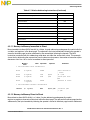
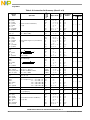
The following revision history table summarizes changes contained in this document. For your
convenience, the page number designators have been linked to the appropriate location.
Revision History
Date
Revision
Level
Description
Page
Number(s)
February,
2006
4
Updated to meet Freescale identity guidelines. N/A
Chapter 5 Instruction Set — Corrected description of CLI instruction. 101

Revision History
CPU08 Central Processor Unit Reference Manual, Rev. 4
4 Freescale Semiconductor

CPU08 Central Processor Unit Reference Manual, Rev. 4
Freescale Semiconductor 5
List of Chapters
Chapter 1 General Description. . . . . . . . . . . . . . . . . . . . . . . . . . . . . . . . . . . . . . . . . . . . . . . .13
Chapter 2 Architecture . . . . . . . . . . . . . . . . . . . . . . . . . . . . . . . . . . . . . . . . . . . . . . . . . . . . . .15
Chapter 3 Resets and Interrupts . . . . . . . . . . . . . . . . . . . . . . . . . . . . . . . . . . . . . . . . . . . . . .23
Chapter 4 Addressing Modes. . . . . . . . . . . . . . . . . . . . . . . . . . . . . . . . . . . . . . . . . . . . . . . . .33
Chapter 5 Instruction Set . . . . . . . . . . . . . . . . . . . . . . . . . . . . . . . . . . . . . . . . . . . . . . . . . . . .59
Chapter 6 Instruction Set Examples . . . . . . . . . . . . . . . . . . . . . . . . . . . . . . . . . . . . . . . . . .155
Glossary. . . . . . . . . . . . . . . . . . . . . . . . . . . . . . . . . . . . . . . . . . . . . . . . . . . . . . . . . . . . . . . . 187
Index. . . . . . . . . . . . . . . . . . . . . . . . . . . . . . . . . . . . . . . . . . . . . . . . . . . . . . . . . . . . . . . . . . . 195

List of Chapters
CPU08 Central Processor Unit Reference Manual, Rev. 4
6 Freescale Semiconductor

CPU08 Central Processor Unit Reference Manual, Rev. 4
Freescale Semiconductor 7
Table of Contents
Chapter 1
General Description
1.1 Introduction . . . . . . . . . . . . . . . . . . . . . . . . . . . . . . . . . . . . . . . . . . . . . . . . . . . . . . . . . . . . . . . . 13
1.2 Features. . . . . . . . . . . . . . . . . . . . . . . . . . . . . . . . . . . . . . . . . . . . . . . . . . . . . . . . . . . . . . . . . . . 13
1.3 Programming Model. . . . . . . . . . . . . . . . . . . . . . . . . . . . . . . . . . . . . . . . . . . . . . . . . . . . . . . . . . 13
1.4 Memory Space. . . . . . . . . . . . . . . . . . . . . . . . . . . . . . . . . . . . . . . . . . . . . . . . . . . . . . . . . . . . . . 14
1.5 Addressing Modes . . . . . . . . . . . . . . . . . . . . . . . . . . . . . . . . . . . . . . . . . . . . . . . . . . . . . . . . . . . 14
1.6 Arithmetic Instructions . . . . . . . . . . . . . . . . . . . . . . . . . . . . . . . . . . . . . . . . . . . . . . . . . . . . . . . . 14
1.7 Binary-Coded Decimal (BCD) Arithmetic Support . . . . . . . . . . . . . . . . . . . . . . . . . . . . . . . . . . . 14
1.8 High-Level Language Support . . . . . . . . . . . . . . . . . . . . . . . . . . . . . . . . . . . . . . . . . . . . . . . . . . 14
1.9 Low-Power Modes . . . . . . . . . . . . . . . . . . . . . . . . . . . . . . . . . . . . . . . . . . . . . . . . . . . . . . . . . . . 14
Chapter 2
Architecture
2.1 Introduction . . . . . . . . . . . . . . . . . . . . . . . . . . . . . . . . . . . . . . . . . . . . . . . . . . . . . . . . . . . . . . . . 15
2.2 CPU08 Registers . . . . . . . . . . . . . . . . . . . . . . . . . . . . . . . . . . . . . . . . . . . . . . . . . . . . . . . . . . . 15
2.2.1 Accumulator . . . . . . . . . . . . . . . . . . . . . . . . . . . . . . . . . . . . . . . . . . . . . . . . . . . . . . . . . . . . . 16
2.2.2 Index Register. . . . . . . . . . . . . . . . . . . . . . . . . . . . . . . . . . . . . . . . . . . . . . . . . . . . . . . . . . . 16
2.2.3 Stack Pointer. . . . . . . . . . . . . . . . . . . . . . . . . . . . . . . . . . . . . . . . . . . . . . . . . . . . . . . . . . . . 17
2.2.4 Program Counter. . . . . . . . . . . . . . . . . . . . . . . . . . . . . . . . . . . . . . . . . . . . . . . . . . . . . . . . . 17
2.2.5 Condition Code Register . . . . . . . . . . . . . . . . . . . . . . . . . . . . . . . . . . . . . . . . . . . . . . . . . . . 18
2.3 CPU08 Functional Description . . . . . . . . . . . . . . . . . . . . . . . . . . . . . . . . . . . . . . . . . . . . . . . . . 19
2.3.1 Internal Timing . . . . . . . . . . . . . . . . . . . . . . . . . . . . . . . . . . . . . . . . . . . . . . . . . . . . . . . . . . . 20
2.3.2 Control Unit . . . . . . . . . . . . . . . . . . . . . . . . . . . . . . . . . . . . . . . . . . . . . . . . . . . . . . . . . . . . . 20
2.3.3 Execution Unit . . . . . . . . . . . . . . . . . . . . . . . . . . . . . . . . . . . . . . . . . . . . . . . . . . . . . . . . . . . 21
2.3.4 Instruction Execution . . . . . . . . . . . . . . . . . . . . . . . . . . . . . . . . . . . . . . . . . . . . . . . . . . . . . . 21
Chapter 3
Resets and Interrupts
3.1 Introduction . . . . . . . . . . . . . . . . . . . . . . . . . . . . . . . . . . . . . . . . . . . . . . . . . . . . . . . . . . . . . . . . 23
3.2 Elements of Reset and Interrupt Processing . . . . . . . . . . . . . . . . . . . . . . . . . . . . . . . . . . . . . . . 23
3.2.1 Recognition . . . . . . . . . . . . . . . . . . . . . . . . . . . . . . . . . . . . . . . . . . . . . . . . . . . . . . . . . . . . . 23
3.2.2 Stacking . . . . . . . . . . . . . . . . . . . . . . . . . . . . . . . . . . . . . . . . . . . . . . . . . . . . . . . . . . . . . . . . 24
3.2.3 Arbitration. . . . . . . . . . . . . . . . . . . . . . . . . . . . . . . . . . . . . . . . . . . . . . . . . . . . . . . . . . . . . . . 25
3.2.4 Masking . . . . . . . . . . . . . . . . . . . . . . . . . . . . . . . . . . . . . . . . . . . . . . . . . . . . . . . . . . . . . . . . 26
3.2.5 Returning to Calling Program. . . . . . . . . . . . . . . . . . . . . . . . . . . . . . . . . . . . . . . . . . . . . . . . 27
3.3 Reset Processing. . . . . . . . . . . . . . . . . . . . . . . . . . . . . . . . . . . . . . . . . . . . . . . . . . . . . . . . . . . . 27
3.3.1 Initial Conditions Established . . . . . . . . . . . . . . . . . . . . . . . . . . . . . . . . . . . . . . . . . . . . . . . . 28
3.3.2 CPU . . . . . . . . . . . . . . . . . . . . . . . . . . . . . . . . . . . . . . . . . . . . . . . . . . . . . . . . . . . . . . . . . . . 28
3.3.3 Operating Mode Selection . . . . . . . . . . . . . . . . . . . . . . . . . . . . . . . . . . . . . . . . . . . . . . . . . . 28

Table of Contents
CPU08 Central Processor Unit Reference Manual, Rev. 4
8 Freescale Semiconductor
3.3.4 Reset Sources . . . . . . . . . . . . . . . . . . . . . . . . . . . . . . . . . . . . . . . . . . . . . . . . . . . . . . . . . . . 29
3.3.5 External Reset . . . . . . . . . . . . . . . . . . . . . . . . . . . . . . . . . . . . . . . . . . . . . . . . . . . . . . . . . . . 29
3.3.6 Active Reset from an Internal Source . . . . . . . . . . . . . . . . . . . . . . . . . . . . . . . . . . . . . . . . . 29
3.4 Interrupt Processing. . . . . . . . . . . . . . . . . . . . . . . . . . . . . . . . . . . . . . . . . . . . . . . . . . . . . . . . . . 29
3.4.1 Interrupt Sources and Priority . . . . . . . . . . . . . . . . . . . . . . . . . . . . . . . . . . . . . . . . . . . . . . . 30
3.4.2 Interrupts in Stop and Wait Modes. . . . . . . . . . . . . . . . . . . . . . . . . . . . . . . . . . . . . . . . . . . . 31
3.4.3 Nesting of Multiple Interrupts . . . . . . . . . . . . . . . . . . . . . . . . . . . . . . . . . . . . . . . . . . . . . . . . 31
3.4.4 Allocating Scratch Space on the Stack . . . . . . . . . . . . . . . . . . . . . . . . . . . . . . . . . . . . . . . . 32
Chapter 4
Addressing Modes
4.1 Introduction . . . . . . . . . . . . . . . . . . . . . . . . . . . . . . . . . . . . . . . . . . . . . . . . . . . . . . . . . . . . . . . . 33
4.2 Addressing Modes . . . . . . . . . . . . . . . . . . . . . . . . . . . . . . . . . . . . . . . . . . . . . . . . . . . . . . . . . . . 33
4.2.1 Inherent. . . . . . . . . . . . . . . . . . . . . . . . . . . . . . . . . . . . . . . . . . . . . . . . . . . . . . . . . . . . . . . . 34
4.2.2 Immediate . . . . . . . . . . . . . . . . . . . . . . . . . . . . . . . . . . . . . . . . . . . . . . . . . . . . . . . . . . . . . . 36
4.2.3 Direct. . . . . . . . . . . . . . . . . . . . . . . . . . . . . . . . . . . . . . . . . . . . . . . . . . . . . . . . . . . . . . . . . . 37
4.2.4 Extended. . . . . . . . . . . . . . . . . . . . . . . . . . . . . . . . . . . . . . . . . . . . . . . . . . . . . . . . . . . . . . . 39
4.2.5 Indexed, No Offset . . . . . . . . . . . . . . . . . . . . . . . . . . . . . . . . . . . . . . . . . . . . . . . . . . . . . . . . 40
4.2.6 Indexed, 8-Bit Offset . . . . . . . . . . . . . . . . . . . . . . . . . . . . . . . . . . . . . . . . . . . . . . . . . . . . . . 40
4.2.7 Indexed, 16-Bit Offset . . . . . . . . . . . . . . . . . . . . . . . . . . . . . . . . . . . . . . . . . . . . . . . . . . . . . 40
4.2.8 Stack Pointer, 8-Bit Offset . . . . . . . . . . . . . . . . . . . . . . . . . . . . . . . . . . . . . . . . . . . . . . . . . . 42
4.2.9 Stack Pointer, 16-Bit Offset . . . . . . . . . . . . . . . . . . . . . . . . . . . . . . . . . . . . . . . . . . . . . . . . . 42
4.2.10 Relative . . . . . . . . . . . . . . . . . . . . . . . . . . . . . . . . . . . . . . . . . . . . . . . . . . . . . . . . . . . . . . . . 44
4.2.11 Memory-to-Memory Immediate to Direct . . . . . . . . . . . . . . . . . . . . . . . . . . . . . . . . . . . . . . . 45
4.2.12 Memory-to-Memory Direct to Direct. . . . . . . . . . . . . . . . . . . . . . . . . . . . . . . . . . . . . . . . . . . 45
4.2.13 Memory-to-Memory Indexed to Direct with Post Increment . . . . . . . . . . . . . . . . . . . . . . . . . 46
4.2.14 Memory-to-Memory Direct to Indexed with Post Increment . . . . . . . . . . . . . . . . . . . . . . . . . 47
4.2.15 Indexed with Post Increment . . . . . . . . . . . . . . . . . . . . . . . . . . . . . . . . . . . . . . . . . . . . . . . . 48
4.2.16 Indexed, 8-Bit Offset with Post Increment . . . . . . . . . . . . . . . . . . . . . . . . . . . . . . . . . . . . . . 49
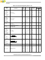
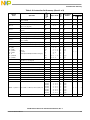
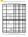
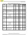
4.3 Instruction Set Summary . . . . . . . . . . . . . . . . . . . . . . . . . . . . . . . . . . . . . . . . . . . . . . . . . . . . . . 49
4.4 Opcode Map . . . . . . . . . . . . . . . . . . . . . . . . . . . . . . . . . . . . . . . . . . . . . . . . . . . . . . . . . . . . . . . 57
Chapter 5
Instruction Set
5.1 Introduction . . . . . . . . . . . . . . . . . . . . . . . . . . . . . . . . . . . . . . . . . . . . . . . . . . . . . . . . . . . . . . . . 59
5.2 Nomenclature. . . . . . . . . . . . . . . . . . . . . . . . . . . . . . . . . . . . . . . . . . . . . . . . . . . . . . . . . . . . . . . 59
5.3 Convention Definitions . . . . . . . . . . . . . . . . . . . . . . . . . . . . . . . . . . . . . . . . . . . . . . . . . . . . . . . . 62
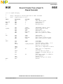
5.4 Instruction Set . . . . . . . . . . . . . . . . . . . . . . . . . . . . . . . . . . . . . . . . . . . . . . . . . . . . . . . . . . . . . . 62
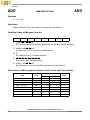
ADC Add with Carry . . . . . . . . . . . . . . . . . . . . . . . . . . . . . . . . . . . . . . . . . . . . . . . . . . 63
ADD Add without Carry. . . . . . . . . . . . . . . . . . . . . . . . . . . . . . . . . . . . . . . . . . . . . . . . 64
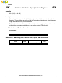
AIS Add Immediate Value (Signed) to Stack Pointer . . . . . . . . . . . . . . . . . . . . . . . . 65
AIX Add Immediate Value (Signed) to Index Register . . . . . . . . . . . . . . . . . . . . . . . 66
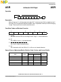
AND Logical AND . . . . . . . . . . . . . . . . . . . . . . . . . . . . . . . . . . . . . . . . . . . . . . . . . . . . 67
ASL Arithmetic Shift Left . . . . . . . . . . . . . . . . . . . . . . . . . . . . . . . . . . . . . . . . . . . . . . 68
ASR Arithmetic Shift Right . . . . . . . . . . . . . . . . . . . . . . . . . . . . . . . . . . . . . . . . . . . . . 69
BCC Branch if Carry Bit Clear. . . . . . . . . . . . . . . . . . . . . . . . . . . . . . . . . . . . . . . . . . . 70
BCLR n Clear Bit n in Memory. . . . . . . . . . . . . . . . . . . . . . . . . . . . . . . . . . . . . . . . . . . . . 71

Table of Contents
CPU08 Central Processor Unit Reference Manual, Rev. 4
Freescale Semiconductor 9
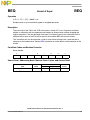
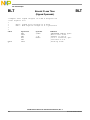
BCS Branch if Carry Bit Set . . . . . . . . . . . . . . . . . . . . . . . . . . . . . . . . . . . . . . . . . . . . 72
BEQ Branch if Equal . . . . . . . . . . . . . . . . . . . . . . . . . . . . . . . . . . . . . . . . . . . . . . . . . . 73
BGE Branch if Greater Than or Equal To . . . . . . . . . . . . . . . . . . . . . . . . . . . . . . . . . . 74
BGT Branch if Greater Than. . . . . . . . . . . . . . . . . . . . . . . . . . . . . . . . . . . . . . . . . . . . 75
BHCC Branch if Half Carry Bit Clear . . . . . . . . . . . . . . . . . . . . . . . . . . . . . . . . . . . . . . . 76
BHCS Branch if Half Carry Bit Set . . . . . . . . . . . . . . . . . . . . . . . . . . . . . . . . . . . . . . . . 77
BHI Branch if Higher . . . . . . . . . . . . . . . . . . . . . . . . . . . . . . . . . . . . . . . . . . . . . . . . . 78
BHS Branch if Higher or Same . . . . . . . . . . . . . . . . . . . . . . . . . . . . . . . . . . . . . . . . . . 79
BIH Branch if IRQ
Pin High . . . . . . . . . . . . . . . . . . . . . . . . . . . . . . . . . . . . . . . . . . . . 80
BIL Branch if IRQ
Pin Low . . . . . . . . . . . . . . . . . . . . . . . . . . . . . . . . . . . . . . . . . . . . 81
BIT Bit Test . . . . . . . . . . . . . . . . . . . . . . . . . . . . . . . . . . . . . . . . . . . . . . . . . . . . . . . . 82
BLE Branch if Less Than or Equal To . . . . . . . . . . . . . . . . . . . . . . . . . . . . . . . . . . . . 83
BLO Branch if Lower . . . . . . . . . . . . . . . . . . . . . . . . . . . . . . . . . . . . . . . . . . . . . . . . . 84
BLS Branch if Lower or Same . . . . . . . . . . . . . . . . . . . . . . . . . . . . . . . . . . . . . . . . . . 85
BLT Branch if Less Than . . . . . . . . . . . . . . . . . . . . . . . . . . . . . . . . . . . . . . . . . . . . . . 86
BMC Branch if Interrupt Mask Clear . . . . . . . . . . . . . . . . . . . . . . . . . . . . . . . . . . . . . . 87
BMI Branch if Minus. . . . . . . . . . . . . . . . . . . . . . . . . . . . . . . . . . . . . . . . . . . . . . . . . . 88
BMS Branch if Interrupt Mask Set. . . . . . . . . . . . . . . . . . . . . . . . . . . . . . . . . . . . . . . . 89
BNE Branch if Not Equal . . . . . . . . . . . . . . . . . . . . . . . . . . . . . . . . . . . . . . . . . . . . . . 90
BPL Branch if Plus . . . . . . . . . . . . . . . . . . . . . . . . . . . . . . . . . . . . . . . . . . . . . . . . . . . 91
BRA Branch Always . . . . . . . . . . . . . . . . . . . . . . . . . . . . . . . . . . . . . . . . . . . . . . . . . . 92
BRA Branch Always . . . . . . . . . . . . . . . . . . . . . . . . . . . . . . . . . . . . . . . . . . . . . . . . . . 93
BRCLR n Branch if Bit n in Memory Clear . . . . . . . . . . . . . . . . . . . . . . . . . . . . . . . . . . . . . 94
BRN Branch Never . . . . . . . . . . . . . . . . . . . . . . . . . . . . . . . . . . . . . . . . . . . . . . . . . . . 95
BRSET n Branch if Bit n in Memory Set. . . . . . . . . . . . . . . . . . . . . . . . . . . . . . . . . . . . . . . 96
BSET n Set Bit n in Memory . . . . . . . . . . . . . . . . . . . . . . . . . . . . . . . . . . . . . . . . . . . . . . 97
BSR Branch to Subroutine . . . . . . . . . . . . . . . . . . . . . . . . . . . . . . . . . . . . . . . . . . . . . 98
CBEQ Compare and Branch if Equal . . . . . . . . . . . . . . . . . . . . . . . . . . . . . . . . . . . . . . 99
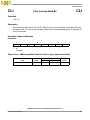
CLC Clear Carry Bit . . . . . . . . . . . . . . . . . . . . . . . . . . . . . . . . . . . . . . . . . . . . . . . . . 100
CLI Clear Interrupt Mask Bit . . . . . . . . . . . . . . . . . . . . . . . . . . . . . . . . . . . . . . . . . . 101
CLR Clear. . . . . . . . . . . . . . . . . . . . . . . . . . . . . . . . . . . . . . . . . . . . . . . . . . . . . . . . . 102
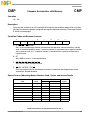
CMP Compare Accumulator with Memory . . . . . . . . . . . . . . . . . . . . . . . . . . . . . . . . 103
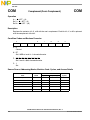
COM Complement (One’s Complement) . . . . . . . . . . . . . . . . . . . . . . . . . . . . . . . . . 104
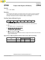
CPHX Compare Index Register with Memory . . . . . . . . . . . . . . . . . . . . . . . . . . . . . . . 105
CPX Compare X (Index Register Low) with Memory . . . . . . . . . . . . . . . . . . . . . . . . 106
DAA Decimal Adjust Accumulator . . . . . . . . . . . . . . . . . . . . . . . . . . . . . . . . . . . . . . 107
DBNZ Decrement and Branch if Not Zero. . . . . . . . . . . . . . . . . . . . . . . . . . . . . . . . . . 109
DEC Decrement . . . . . . . . . . . . . . . . . . . . . . . . . . . . . . . . . . . . . . . . . . . . . . . . . . . . 110
DIV Divide . . . . . . . . . . . . . . . . . . . . . . . . . . . . . . . . . . . . . . . . . . . . . . . . . . . . . . . . 111
EOR Exclusive-OR Memory with Accumulator . . . . . . . . . . . . . . . . . . . . . . . . . . . . . 112
INC Increment . . . . . . . . . . . . . . . . . . . . . . . . . . . . . . . . . . . . . . . . . . . . . . . . . . . . . 113
JMP Jump. . . . . . . . . . . . . . . . . . . . . . . . . . . . . . . . . . . . . . . . . . . . . . . . . . . . . . . . . 114
JSR Jump to Subroutine . . . . . . . . . . . . . . . . . . . . . . . . . . . . . . . . . . . . . . . . . . . . . 115
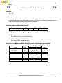
LDA Load Accumulator from Memory . . . . . . . . . . . . . . . . . . . . . . . . . . . . . . . . . . . 116
LDHX Load Index Register from Memory . . . . . . . . . . . . . . . . . . . . . . . . . . . . . . . . . . 117
LDX Load X (Index Register Low) from Memory . . . . . . . . . . . . . . . . . . . . . . . . . . . 118
LSL Logical Shift Left. . . . . . . . . . . . . . . . . . . . . . . . . . . . . . . . . . . . . . . . . . . . . . . . 119
LSR Logical Shift Right . . . . . . . . . . . . . . . . . . . . . . . . . . . . . . . . . . . . . . . . . . . . . . 120
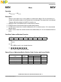
MOV Move. . . . . . . . . . . . . . . . . . . . . . . . . . . . . . . . . . . . . . . . . . . . . . . . . . . . . . . . . 121

Table of Contents
CPU08 Central Processor Unit Reference Manual, Rev. 4
10 Freescale Semiconductor
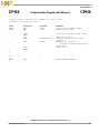
MUL Unsigned Multiply . . . . . . . . . . . . . . . . . . . . . . . . . . . . . . . . . . . . . . . . . . . . . . . 122
NEG Negate (Two’s Complement) . . . . . . . . . . . . . . . . . . . . . . . . . . . . . . . . . . . . . . 123
NOP No Operation . . . . . . . . . . . . . . . . . . . . . . . . . . . . . . . . . . . . . . . . . . . . . . . . . . 124
NSA Nibble Swap Accumulator . . . . . . . . . . . . . . . . . . . . . . . . . . . . . . . . . . . . . . . . 125
ORA Inclusive-OR Accumulator and Memory. . . . . . . . . . . . . . . . . . . . . . . . . . . . . . 126
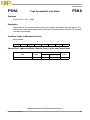
PSHA Push Accumulator onto Stack . . . . . . . . . . . . . . . . . . . . . . . . . . . . . . . . . . . . . 127
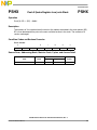
PSHH Push H (Index Register High) onto Stack. . . . . . . . . . . . . . . . . . . . . . . . . . . . . 128
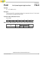
PSHX Push X (Index Register Low) onto Stack . . . . . . . . . . . . . . . . . . . . . . . . . . . . . 129
PULA Pull Accumulator from Stack . . . . . . . . . . . . . . . . . . . . . . . . . . . . . . . . . . . . . . 130
PULH Pull H (Index Register High) from Stack. . . . . . . . . . . . . . . . . . . . . . . . . . . . . . 131
PULX Pull X (Index Register Low) from Stack . . . . . . . . . . . . . . . . . . . . . . . . . . . . . . 132
ROL Rotate Left through Carry. . . . . . . . . . . . . . . . . . . . . . . . . . . . . . . . . . . . . . . . . 133
ROR Rotate Right through Carry . . . . . . . . . . . . . . . . . . . . . . . . . . . . . . . . . . . . . . . 134
RSP Reset Stack Pointer . . . . . . . . . . . . . . . . . . . . . . . . . . . . . . . . . . . . . . . . . . . . . 135
RTI Return from Interrupt . . . . . . . . . . . . . . . . . . . . . . . . . . . . . . . . . . . . . . . . . . . . 136
RTS Return from Subroutine . . . . . . . . . . . . . . . . . . . . . . . . . . . . . . . . . . . . . . . . . . 137
SBC Subtract with Carry. . . . . . . . . . . . . . . . . . . . . . . . . . . . . . . . . . . . . . . . . . . . . . 138
SEC Set Carry Bit . . . . . . . . . . . . . . . . . . . . . . . . . . . . . . . . . . . . . . . . . . . . . . . . . . . 139
SEI Set Interrupt Mask Bit. . . . . . . . . . . . . . . . . . . . . . . . . . . . . . . . . . . . . . . . . . . . 140
STA Store Accumulator in Memory . . . . . . . . . . . . . . . . . . . . . . . . . . . . . . . . . . . . . 141
STHX Store Index Register . . . . . . . . . . . . . . . . . . . . . . . . . . . . . . . . . . . . . . . . . . . . 142
STOP Enable IRQ
Pin, Stop Oscillator . . . . . . . . . . . . . . . . . . . . . . . . . . . . . . . . . . . . 143
STX Store X (Index Register Low) in Memory . . . . . . . . . . . . . . . . . . . . . . . . . . . . . 144
SUB Subtract . . . . . . . . . . . . . . . . . . . . . . . . . . . . . . . . . . . . . . . . . . . . . . . . . . . . . . 145
SWI Software Interrupt. . . . . . . . . . . . . . . . . . . . . . . . . . . . . . . . . . . . . . . . . . . . . . . 146
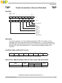
TAP Transfer Accumulator to Processor Status Byte . . . . . . . . . . . . . . . . . . . . . . . 147
TAX Transfer Accumulator to X (Index Register Low) . . . . . . . . . . . . . . . . . . . . . . 148
TPA Transfer Processor Status Byte to Accumulator . . . . . . . . . . . . . . . . . . . . . . . 149
TST Test for Negative or Zero . . . . . . . . . . . . . . . . . . . . . . . . . . . . . . . . . . . . . . . . . 150
TSX Transfer Stack Pointer to Index Register . . . . . . . . . . . . . . . . . . . . . . . . . . . . 151
TXA Transfer X (Index Register Low) to Accumulator . . . . . . . . . . . . . . . . . . . . . . . 152
TXS Transfer Index Register to Stack Pointer . . . . . . . . . . . . . . . . . . . . . . . . . . . . . 153
WAIT Enable Interrupts; Stop Processor . . . . . . . . . . . . . . . . . . . . . . . . . . . . . . . . . . 154
Chapter 6
Instruction Set Examples
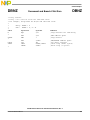
6.1 Introduction . . . . . . . . . . . . . . . . . . . . . . . . . . . . . . . . . . . . . . . . . . . . . . . . . . . . . . . . . . . . . . . 155
6.2 M68HC08 Unique Instructions . . . . . . . . . . . . . . . . . . . . . . . . . . . . . . . . . . . . . . . . . . . . . . . . . 155
6.3 Code Examples . . . . . . . . . . . . . . . . . . . . . . . . . . . . . . . . . . . . . . . . . . . . . . . . . . . . . . . . . . . . 155
AIS Add Immediate Value (Signed) to Stack Pointer . . . . . . . . . . . . . . . . . . . . . . . 156
AIX Add Immediate Value (Signed) to Index Register . . . . . . . . . . . . . . . . . . . . . . 158
BGE Branch if Greater Than or Equal To . . . . . . . . . . . . . . . . . . . . . . . . . . . . . . . . . 159
BGT Branch if Greater Than. . . . . . . . . . . . . . . . . . . . . . . . . . . . . . . . . . . . . . . . . . . 160
BLE Branch if Less Than or Equal To . . . . . . . . . . . . . . . . . . . . . . . . . . . . . . . . . . . 161
BLT Branch if Less Than . . . . . . . . . . . . . . . . . . . . . . . . . . . . . . . . . . . . . . . . . . . . . 162
CBEQ Compare and Branch if Equal . . . . . . . . . . . . . . . . . . . . . . . . . . . . . . . . . . . . . 163
CBEQA Compare A with Immediate . . . . . . . . . . . . . . . . . . . . . . . . . . . . . . . . . . . . . . . 164
CBEQX Compare X with Immediate . . . . . . . . . . . . . . . . . . . . . . . . . . . . . . . . . . . . . . . 165

Table of Contents
CPU08 Central Processor Unit Reference Manual, Rev. 4
Freescale Semiconductor 11
CLRH Clear H (Index Register High) . . . . . . . . . . . . . . . . . . . . . . . . . . . . . . . . . . . . . 166
CPHX Compare Index Register with Memory . . . . . . . . . . . . . . . . . . . . . . . . . . . . . . . 167
DAA Decimal Adjust Accumulator . . . . . . . . . . . . . . . . . . . . . . . . . . . . . . . . . . . . . . 168
DBNZ Decrement and Branch if Not Zero. . . . . . . . . . . . . . . . . . . . . . . . . . . . . . . . . . 169
DIV Divide . . . . . . . . . . . . . . . . . . . . . . . . . . . . . . . . . . . . . . . . . . . . . . . . . . . . . . . . 170
LDHX Load Index Register with Memory . . . . . . . . . . . . . . . . . . . . . . . . . . . . . . . . . 173
MOV Move. . . . . . . . . . . . . . . . . . . . . . . . . . . . . . . . . . . . . . . . . . . . . . . . . . . . . . . . . 174
NSA Nibble Swap Accumulator . . . . . . . . . . . . . . . . . . . . . . . . . . . . . . . . . . . . . . . . 175
PSHA Push Accumulator onto Stack . . . . . . . . . . . . . . . . . . . . . . . . . . . . . . . . . . . . . 176
PSHH Push H (Index Register High) onto Stack. . . . . . . . . . . . . . . . . . . . . . . . . . . . . 177
PSHX Push X (Index Register Low) onto Stack . . . . . . . . . . . . . . . . . . . . . . . . . . . . . 178
PULA Pull Accumulator from Stack . . . . . . . . . . . . . . . . . . . . . . . . . . . . . . . . . . . . . . 179
PULH Pull H (Index Register High) from Stack. . . . . . . . . . . . . . . . . . . . . . . . . . . . . . 180
PULX Pull X (Index Register Low) from Stack . . . . . . . . . . . . . . . . . . . . . . . . . . . . . . 181
STHX Store Index Register . . . . . . . . . . . . . . . . . . . . . . . . . . . . . . . . . . . . . . . . . . . . 182
TAP Transfer Accumulator to Condition Code Register. . . . . . . . . . . . . . . . . . . . . . 183
TPA Transfer Condition Code Register to Accumulator. . . . . . . . . . . . . . . . . . . . . . 184
TSX Transfer Stack Pointer to Index Register . . . . . . . . . . . . . . . . . . . . . . . . . . . . 185
TXS Transfer Index Register to Stack Pointer . . . . . . . . . . . . . . . . . . . . . . . . . . . . . 186
Glossary
Glossary. . . . . . . . . . . . . . . . . . . . . . . . . . . . . . . . . . . . . . . . . . . . . . . . . . . . . . . . . . . . . . . . . . 187
Index
Index . . . . . . . . . . . . . . . . . . . . . . . . . . . . . . . . . . . . . . . . . . . . . . . . . . . . . . . . . . . . . . . . . . . . 195

Table of Contents
CPU08 Central Processor Unit Reference Manual, Rev. 4
12 Freescale Semiconductor

CPU08 Central Processor Unit Reference Manual, Rev. 4
Freescale Semiconductor 13
Chapter 1
General Description
1.1 Introduction
The CPU08 is the central processor unit (CPU) of the Motorola M68HC08 Family of microcontroller units
(MCU). The fully object code compatible CPU08 offers M68HC05 users increased performance with no
loss of time or software investment in their M68HC05-based applications. The CPU08 also appeals to
users of other MCU architectures who need the CPU08 combination of speed, low power, processing
capabilities, and cost effectiveness.
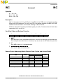
1.2 Features
CPU08 features include:
• Full object-code compatibility with M68HC05 Family
• 16-bit stack pointer with stack manipulation instructions
• 16-bit index register (H:X) with high-byte and low-byte manipulation instructions
• 8-MHz CPU standard bus frequency
• 64-Kbyte program/data memory space
• 16 addressing modes
• 78 new opcodes
• Memory-to-memory data moves without using accumulator
• Fast 8-bit by 8-bit multiply and 16-bit by 8-bit divide instructions
• Enhanced binary-coded decimal (BCD) data handling
• Expandable internal bus definition for extension of addressing range beyond 64 Kbytes
• Flexible internal bus definition to accommodate CPU performance-enhancing peripherals such as
a direct memory access (DMA) controller
• Low-power stop and wait modes
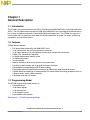
1.3 Programming Model
The CPU08 programming model consists of:
• 8-bit accumulator
• 16-bit index register
• 16-bit stack pointer
• 16-bit program counter
• 8-bit condition code register
See Figure 2-1. CPU08 Programming Model.

General Description
CPU08 Central Processor Unit Reference Manual, Rev. 4
14 Freescale Semiconductor
1.4 Memory Space
Program memory space and data memory space are contiguous over a 64-Kbyte addressing range.
Addition of a page-switching peripheral allows extension of the addressing range beyond 64 Kbytes.
1.5 Addressing Modes
The CPU08 has a total of 16 addressing modes:
• Inherent
•Immediate
•Direct
• Extended
• Indexed
– No offset
– No offset, post increment
– 8-bit offset
– 8-bit offset, post increment
– 16-bit offset
• Stack pointer
– 8-bit offset
– 16-bit offset
• Relative
• Memory-to-memory (four modes)
Refer to Chapter 4 Addressing Modes for a detailed description of the CPU08 addressing modes.
1.6 Arithmetic Instructions
The CPU08 arithmetic functions include:
• Addition with and without carry
• Subtraction with and without carry
• A fast 16-bit by 8-bit unsigned division
• A fast 8-bit by 8-bit unsigned multiply
1.7 Binary-Coded Decimal (BCD) Arithmetic Support
To support binary-coded decimal (BCD) arithmetic applications, the CPU08 has a decimal adjust
accumulator (DAA) instruction and a nibble swap accumulator (NSA) instruction.
1.8 High-Level Language Support
The 16-bit index register, 16-bit stack pointer, 8-bit signed branch instructions, and associated
instructions are designed to support the efficient use of high-level language (HLL) compilers with the
CPU08.
1.9 Low-Power Modes
The WAIT and STOP instructions reduce the power consumption of the CPU08-based MCU. The WAIT
instruction stops only the CPU clock and therefore uses more power than the STOP instruction, which
stops both the CPU clock and the peripheral clocks. In most modules, clocks can be shut off in wait mode.

CPU08 Central Processor Unit Reference Manual, Rev. 4
Freescale Semiconductor 15
Chapter 2
Architecture
2.1 Introduction
This section describes the CPU08 registers.
2.2 CPU08 Registers
Figure 2-1 shows the five CPU08 registers. The CPU08 registers are not part of the memory map.
70
A ACCUMULATOR (A)
15 8 7 0
H X INDEX REGISTER (H:X)
15 0
STACK POINTER (SP)
15 0
PROGRAM COUNTER (PC)
70
CONDITION CODE
REGISTER (CCR)
V11HI NZC
CARRY/BORROW FLAG (C)
TWO’S COMPLEMENT OVERFLOW
FLAG (V)
ZERO FLAG (Z)
HALF-CARRY FLAG (H)
NEGATIVE FLAG (N)
INTERRUPT MASK (I)
Figure 2-1. CPU08 Programming Model

Architecture
CPU08 Central Processor Unit Reference Manual, Rev. 4
16 Freescale Semiconductor
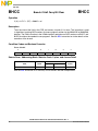
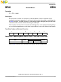
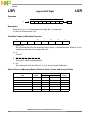
2.2.1 Accumulator
The accumulator (A) shown in Figure 2-2 is a general-purpose 8-bit register. The central processor unit
(CPU) uses the accumulator to hold operands and results of arithmetic and non-arithmetic operations.
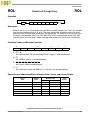
2.2.2 Index Register
The 16-bit index register (H:X) shown in Figure 2-3 allows the user to index or address a 64-Kbyte
memory space. The concatenated 16-bit register is called H:X. The upper byte of the index register is
called H. The lower byte of the index register is called X. H is cleared by reset. When H = 0 and no
instructions that affect H are used, H:X is functionally identical to the IX register of the M6805 Family.
In the indexed addressing modes, the CPU uses the contents of H:X to determine the effective address
of the operand. H:X can also serve as a temporary data storage location. See 4.2.5 Indexed, No Offset;
4.2.6 Indexed, 8-Bit Offset; and 4.2.7 Indexed, 16-Bit Offset.
Bit 7654321Bit 0
Read:
Write:
Reset:XXXXXXXX
X = Indeterminate
Figure 2-2. Accumulator (A)
Bit 151413121110987654321Bit 0
Read:
Write:
Reset:X XXXXXXXXXXXXXXX
X = Indeterminate
Figure 2-3. Index Register (H:X)

CPU08 Registers
CPU08 Central Processor Unit Reference Manual, Rev. 4
Freescale Semiconductor 17
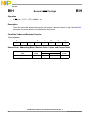
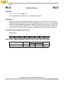
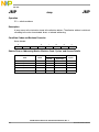
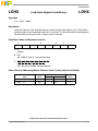
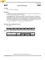
2.2.3 Stack Pointer
The stack pointer (SP) shown in Figure 2-4 is a 16-bit register that contains the address of the next
location on the stack. During a reset, the stack pointer is preset to $00FF to provide compatibility with the
M6805 Family.
NOTE
The reset stack pointer (RSP) instruction sets the least significant byte to
$FF and does not affect the most significant byte.
The address in the stack pointer decrements as data is pushed onto the stack and increments as data is
pulled from the stack. The SP always points to the next available (empty) byte on the stack.
The CPU08 has stack pointer 8- and 16-bit offset addressing modes that allow the stack pointer to be
used as an index register to access temporary variables on the stack. The CPU uses the contents in the
SP register to determine the effective address of the operand. See 4.2.8 Stack Pointer, 8-Bit Offset and
4.2.9 Stack Pointer, 16-Bit Offset.
NOTE
Although preset to $00FF, the location of the stack is arbitrary and may be
relocated by the user to anywhere that random-access memory (RAM)
resides within the memory map. Moving the SP out of page 0 ($0000 to
$00FF) will free up address space, which may be accessed using the
efficient direct addressing mode.
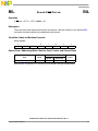
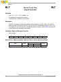
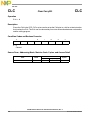
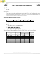
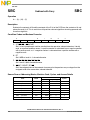
2.2.4 Program Counter
The program counter (PC) shown in Figure 2-5 is a 16-bit register that contains the address of the next
instruction or operand to be fetched.
Normally, the address in the program counter automatically increments to the next sequential memory
location every time an instruction or operand is fetched. Jump, branch, and interrupt operations load the
program counter with an address other than that of the next sequential location.
During reset, the PC is loaded with the contents of the reset vector located at $FFFE and $FFFF. This
represents the address of the first instruction to be executed after the reset state is exited.
Bit 151413121110987654321Bit 0
Read:
Write:
Reset:0 000000011111111
Figure 2-4. Stack Pointer (SP)
Bit 151413121110987654321Bit 0
Read:
Write:
Reset: Loaded with vector from $FFFE and $FFFF
Figure 2-5. Program Counter (PC)

Architecture
CPU08 Central Processor Unit Reference Manual, Rev. 4
18 Freescale Semiconductor
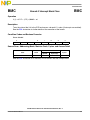
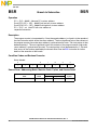
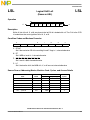
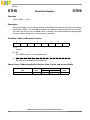
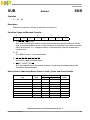
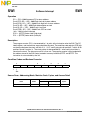
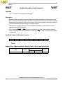
2.2.5 Condition Code Register
The 8-bit condition code register (CCR) shown in Figure 2-6 contains the interrupt mask and five flags
that indicate the results of the instruction just executed. Bits five and six are permanently set to logic 1.
V — Overflow Flag
The CPU sets the overflow flag when a two's complement overflow occurs as a result of an operation.
The overflow flag bit is utilized by the signed branch instructions:
Branch if greater than, BGT
Branch if greater than or equal to, BGE
Branch if less than or equal to, BLE
Branch if less than, BLT
This bit is set by these instructions, although its resulting value holds no meaning:
Arithmetic shift left, ASL
Arithmetic shift right, ASR
Logical shift left, LSL
Logical shift right, LSR
Rotate left through carry, ROL
Rotate right through carry, ROR
H — Half-Carry Flag
The CPU sets the half-carry flag when a carry occurs between bits 3 and 4 of the accumulator during
an add-without-carry (ADD) or add-with-carry (ADC) operation. The half-carry flag is required for
binary-coded (BCD) arithmetic operations. The decimal adjust accumulator (DAA) instruction uses the
state of the H and C flags to determine the appropriate correction factor.
I — Interrupt Mask
When the interrupt mask is set, all interrupts are disabled. Interrupts are enabled when the interrupt
mask is cleared. When an interrupt occurs, the interrupt mask is automatically set after the CPU
registers are saved on the stack, but before the interrupt vector is fetched.
NOTE
To maintain M6805 compatibility, the H register is not stacked
automatically. If the interrupt service routine uses X (and H is not clear),
then the user must stack and unstack H using the push H (index register
high) onto stack (PSHH) and pull H (index register high) from stack (PULH)
instructions within the interrupt service routine.
If an interrupt occurs while the interrupt mask is set, the interrupt is latched. Interrupts in order of priority
are serviced as soon as the I bit is cleared.
Bit 7654321Bit 0
Read:
V11HI NZC
Write:
Reset:X11X1XXX
X = Indeterminate
Figure 2-6. Condition Code Register (CCR)

CPU08 Functional Description
CPU08 Central Processor Unit Reference Manual, Rev. 4
Freescale Semiconductor 19
A return-from-interrupt (RTI) instruction pulls the CPU registers from the stack, restoring the interrupt
mask to its cleared state. After any reset, the interrupt mask is set and can only be cleared by a
software instruction. See Chapter 3 Resets and Interrupts.
N — Negative Flag
The CPU sets the negative flag when an arithmetic operation, logical operation, or data manipulation
produces a negative result.
Z — Zero Flag
The CPU sets the zero flag when an arithmetic operation, logical operation, or data manipulation
produces a result of $00.
C — Carry/Borrow Flag
The CPU sets the carry/borrow flag when an addition operation produces a carry out of bit 7 of the
accumulator or when a subtraction operation requires a borrow. Some logical operations and data
manipulation instructions also clear or set the carry/borrow flag (as in bit test and branch instructions and
shifts and rotates).
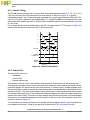
2.3 CPU08 Functional Description
This subsection is an overview of the architecture of the M68HC08 CPU with functional descriptions of
the major blocks of the CPU.
The CPU08, as shown in Figure 2-7, is divided into two main blocks:
• Control unit
• Execution unit
The control unit contains a finite state machine along with miscellaneous control and timing logic. The
outputs of this block drive the execution unit, which contains the arithmetic logic unit (ALU), registers, and
bus interface.
Figure 2-7. CPU08 Block Diagram
CONTROL UNIT
EXECUTION UNIT
INTERNAL
ADDRESS BUS
INTERNAL
DATA BUS
STATUS
SIGNALS
CONTROL
SIGNALS

Architecture
CPU08 Central Processor Unit Reference Manual, Rev. 4
20 Freescale Semiconductor
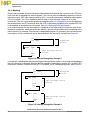
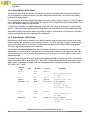
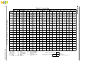
2.3.1 Internal Timing
The CPU08 derives its timing from a 4-phase clock, each phase identified as either T1, T2, T3, or T4. A
CPU bus cycle consists of one clock pulse from each phase, as shown in Figure 2-8. To simplify
subsequent diagrams, the T clocks have been combined into a single signal called the CPU clock. The
start of a CPU cycle is defined as the leading edge of T1, though the address associated with this cycle
does not drive the address bus until T3. Note that the new address leads the associated data by one-half
of a bus cycle.
For example, the data read associated with a new PC value generated in T1/T2 of cycle 1 in Figure 2-8
would not be read into the control unit until T2 of the next cycle.
Figure 2-8. Internal Timing Detail
2.3.2 Control Unit
The control unit consists of:
• Sequencer
• Control store
• Random control logic
These blocks make up a finite state machine, which generates all the controls for the execution unit.
The sequencer provides the next state of the machine to the control store based on the contents of the
instruction register (IR) and the current state of the machine. The control store is strobed (enabled) when
the next state input is stable, producing an output that represents the decoded next state condition for the
execution unit (EU). This result, with the help of some random logic, is used to generate the control signals
that configure the execution unit. The random logic selects the appropriate signals and adds timing to the
outputs of the control store. The control unit fires once per bus cycle but runs almost a full cycle ahead of
the execution unit to decode and generate all the controls for the next cycle. The sequential nature of the
machine is shown in Figure 2-9.
The sequencer also contains and controls the opcode lookahead register, which is used to prefetch the
next sequential instruction. Timing of this operation is discussed in 2.3.4 Instruction Execution.
T1
T2
T3
T4 T1 T2 T3 T4
CPU CLOCK
INTERNAL
ADDRESS BUS
INTERNAL
DATA BUS
DATA CYCLE
ADDR. CYCLE N
EXECUTE
CYCLE N
CYCLE 1 CYCLE 2
T1
T2
T3
T4
Page is loading ...
Page is loading ...
Page is loading ...
Page is loading ...
Page is loading ...
Page is loading ...
Page is loading ...
Page is loading ...
Page is loading ...
Page is loading ...
Page is loading ...
Page is loading ...
Page is loading ...
Page is loading ...
Page is loading ...
Page is loading ...
Page is loading ...
Page is loading ...
Page is loading ...
Page is loading ...
Page is loading ...
Page is loading ...
Page is loading ...
Page is loading ...
Page is loading ...
Page is loading ...
Page is loading ...
Page is loading ...
Page is loading ...
Page is loading ...
Page is loading ...
Page is loading ...
Page is loading ...
Page is loading ...
Page is loading ...
Page is loading ...
Page is loading ...
Page is loading ...
Page is loading ...
Page is loading ...
Page is loading ...
Page is loading ...
Page is loading ...
Page is loading ...
Page is loading ...
Page is loading ...
Page is loading ...
Page is loading ...
Page is loading ...
Page is loading ...
Page is loading ...
Page is loading ...
Page is loading ...
Page is loading ...
Page is loading ...
Page is loading ...
Page is loading ...
Page is loading ...
Page is loading ...
Page is loading ...
Page is loading ...
Page is loading ...
Page is loading ...
Page is loading ...
Page is loading ...
Page is loading ...
Page is loading ...
Page is loading ...
Page is loading ...
Page is loading ...
Page is loading ...
Page is loading ...
Page is loading ...
Page is loading ...
Page is loading ...
Page is loading ...
Page is loading ...
Page is loading ...
Page is loading ...
Page is loading ...
Page is loading ...
Page is loading ...
Page is loading ...
Page is loading ...
Page is loading ...
Page is loading ...
Page is loading ...
Page is loading ...
Page is loading ...
Page is loading ...
Page is loading ...
Page is loading ...
Page is loading ...
Page is loading ...
Page is loading ...
Page is loading ...
Page is loading ...
Page is loading ...
Page is loading ...
Page is loading ...
Page is loading ...
Page is loading ...
Page is loading ...
Page is loading ...
Page is loading ...
Page is loading ...
Page is loading ...
Page is loading ...
Page is loading ...
Page is loading ...
Page is loading ...
Page is loading ...
Page is loading ...
Page is loading ...
Page is loading ...
Page is loading ...
Page is loading ...
Page is loading ...
Page is loading ...
Page is loading ...
Page is loading ...
Page is loading ...
Page is loading ...
Page is loading ...
Page is loading ...
Page is loading ...
Page is loading ...
Page is loading ...
Page is loading ...
Page is loading ...
Page is loading ...
Page is loading ...
Page is loading ...
Page is loading ...
Page is loading ...
Page is loading ...
Page is loading ...
Page is loading ...
Page is loading ...
Page is loading ...
Page is loading ...
Page is loading ...
Page is loading ...
Page is loading ...
Page is loading ...
Page is loading ...
Page is loading ...
Page is loading ...
Page is loading ...
Page is loading ...
Page is loading ...
Page is loading ...
Page is loading ...
Page is loading ...
Page is loading ...
Page is loading ...
Page is loading ...
Page is loading ...
Page is loading ...
Page is loading ...
Page is loading ...
Page is loading ...
Page is loading ...
Page is loading ...
Page is loading ...
Page is loading ...
Page is loading ...
Page is loading ...
Page is loading ...
Page is loading ...
Page is loading ...
Page is loading ...
Page is loading ...
Page is loading ...
Page is loading ...
Page is loading ...
Page is loading ...
Page is loading ...
Page is loading ...
Page is loading ...
-
 1
1
-
 2
2
-
 3
3
-
 4
4
-
 5
5
-
 6
6
-
 7
7
-
 8
8
-
 9
9
-
 10
10
-
 11
11
-
 12
12
-
 13
13
-
 14
14
-
 15
15
-
 16
16
-
 17
17
-
 18
18
-
 19
19
-
 20
20
-
 21
21
-
 22
22
-
 23
23
-
 24
24
-
 25
25
-
 26
26
-
 27
27
-
 28
28
-
 29
29
-
 30
30
-
 31
31
-
 32
32
-
 33
33
-
 34
34
-
 35
35
-
 36
36
-
 37
37
-
 38
38
-
 39
39
-
 40
40
-
 41
41
-
 42
42
-
 43
43
-
 44
44
-
 45
45
-
 46
46
-
 47
47
-
 48
48
-
 49
49
-
 50
50
-
 51
51
-
 52
52
-
 53
53
-
 54
54
-
 55
55
-
 56
56
-
 57
57
-
 58
58
-
 59
59
-
 60
60
-
 61
61
-
 62
62
-
 63
63
-
 64
64
-
 65
65
-
 66
66
-
 67
67
-
 68
68
-
 69
69
-
 70
70
-
 71
71
-
 72
72
-
 73
73
-
 74
74
-
 75
75
-
 76
76
-
 77
77
-
 78
78
-
 79
79
-
 80
80
-
 81
81
-
 82
82
-
 83
83
-
 84
84
-
 85
85
-
 86
86
-
 87
87
-
 88
88
-
 89
89
-
 90
90
-
 91
91
-
 92
92
-
 93
93
-
 94
94
-
 95
95
-
 96
96
-
 97
97
-
 98
98
-
 99
99
-
 100
100
-
 101
101
-
 102
102
-
 103
103
-
 104
104
-
 105
105
-
 106
106
-
 107
107
-
 108
108
-
 109
109
-
 110
110
-
 111
111
-
 112
112
-
 113
113
-
 114
114
-
 115
115
-
 116
116
-
 117
117
-
 118
118
-
 119
119
-
 120
120
-
 121
121
-
 122
122
-
 123
123
-
 124
124
-
 125
125
-
 126
126
-
 127
127
-
 128
128
-
 129
129
-
 130
130
-
 131
131
-
 132
132
-
 133
133
-
 134
134
-
 135
135
-
 136
136
-
 137
137
-
 138
138
-
 139
139
-
 140
140
-
 141
141
-
 142
142
-
 143
143
-
 144
144
-
 145
145
-
 146
146
-
 147
147
-
 148
148
-
 149
149
-
 150
150
-
 151
151
-
 152
152
-
 153
153
-
 154
154
-
 155
155
-
 156
156
-
 157
157
-
 158
158
-
 159
159
-
 160
160
-
 161
161
-
 162
162
-
 163
163
-
 164
164
-
 165
165
-
 166
166
-
 167
167
-
 168
168
-
 169
169
-
 170
170
-
 171
171
-
 172
172
-
 173
173
-
 174
174
-
 175
175
-
 176
176
-
 177
177
-
 178
178
-
 179
179
-
 180
180
-
 181
181
-
 182
182
-
 183
183
-
 184
184
-
 185
185
-
 186
186
-
 187
187
-
 188
188
-
 189
189
-
 190
190
-
 191
191
-
 192
192
-
 193
193
-
 194
194
-
 195
195
-
 196
196
-
 197
197
-
 198
198
-
 199
199
-
 200
200


Ask a question and I''ll find the answer in the document
Finding information in a document is now easier with AI
Related papers
Other documents
-
Freescale Semiconductor M68HC08AD Reference guide
-
Motorola M68HC08 Designer Reference Manual
-
 Erard 6502 Owner's manual
-
Mitsubishi Electric MELSEC iQ-R Programming Manual
-
-
-
Lenovo 70A69001NA User manual
-
-
Hitachi H8/300L Series Programming Manual
-
Hyundai GMS800 User manual
