

2
Main Features . . . . . . . . . . . . . . . . . . . . . . . . . . .3
Conrming Package Contents . . . . . . . . . . . .4
Panel Descriptions . . . . . . . . . . . . . . . . . . . . . . .6
Front Panel . . . . . . . . . . . . . . . . . . . . . . . . . . . . 6
Rear Panel . . . . . . . . . . . . . . . . . . . . . . 9
USB Driver Installation . . . . . . . . . . . . . . . . . 11
Install the USB Driver (Windows) . . . . . .11
Install the USB Driver (Mac OS X) . . . . . .13
Conrm that Sound Can Be Heard . . . .14
Basic Operation . . . . . . . . . . . . . . . . . . . . . . . . 16
Connecting Equipment . . . . . . . . . . . . . . .16
Turning the Power On/O . . . . . . . . . . . .16
Turning the Power On . . . . . . . . . .16
Turning the Power O . . . . . . . . . .17
Making the Power
Automatically Turn O After a
Time (Auto O) . . . . . . . . . . . . . . . .17
Checking the Levels . . . . . . . . . . . . . . . . . .18
Adjusting the Audio Signals . . . . . . . . . . 19
Adjusting the Mic Preamp and
Compressor . . . . . . . . . . . . . . . . . . . .19
Adjusting the Attenuator . . . . . . .22
Adjusting the Direct Monitor
Settings . . . . . . . . . . . . . . . . . . . . . . . .23
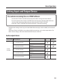
Setting Input and Output Device . . . . .25
Using the STUDIO-CAPTURE Control Panel 27
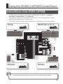
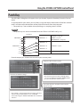
Internal Blocks of the STUDIO-CAPTURE 27
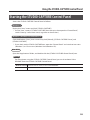
Starting the STUDIO-CAPTURE
Control Panel . . . . . . . . . . . . . . . . . . . . . . . .29
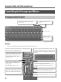
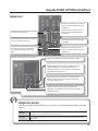
Controlling the Preamps and Mixers . .30
Preamp Control Screen . . . . . . . . .30
Attenuator Screen . . . . . . . . . . . . . .32
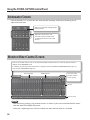
Monitor Mixer Control Screen . . . 32
Patch Bay . . . . . . . . . . . . . . . . . . . . . .37
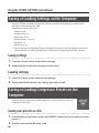
Saving or Loading Settings on the
Computer . . . . . . . . . . . . . . . . . . . . . . . . . . .38
Saving or Loading Compressor
Presets on the Computer . . . . . . . . . . . . .38
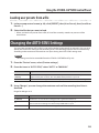
Changing the AUTO-SENS Settings. . . .39
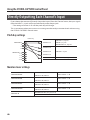
Directly Outputting Each Channel’s
Input . . . . . . . . . . . . . . . . . . . . . . . . . . . . . . . .40
Synchronizing with Other Devices . . . .41
Initializing the Settings . . . . . . . . . . . . . . .41
Checking the Signal Flow . . . . . . . . . . . . .41
USB Driver Settings . . . . . . . . . . . . . . . . . . .42
View in Foreground . . . . . . . . . . . . . . . . . .42
Changing the System Settings . . . . . . . . . . 43
Advanced Operation . . . . . . . . . . . . . . . . . . . 45
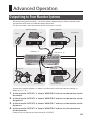
Outputting to Four Monitor Systems . . 45
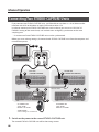
Connecting Two STUDIO-CAPTURE
Units . . . . . . . . . . . . . . . . . . . . . . . . . . . . . . . . .46
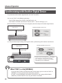
Synchronizing with Another Digital
Device . . . . . . . . . . . . . . . . . . . . . . . . . . . . . . .52
Appendices . . . . . . . . . . . . . . . . . . . . . . . . . . . . 53
Sampling Rate Setting . . . . . . . . . . . . . . . .53
Limitations When Using the 192 kHz
Setting . . . . . . . . . . . . . . . . . . . . . . . . . . . . . . .53
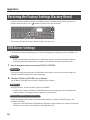
Restoring the Factory Settings
(Factory Reset) . . . . . . . . . . . . . . . . . . . . . . .54
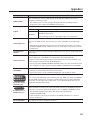
USB Driver Settings . . . . . . . . . . . . . . . . . . .54
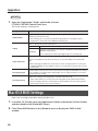
Mac OS X MIDI Settings . . . . . . . . . . . . . . .56
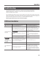
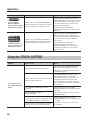
Troubleshooting . . . . . . . . . . . . . . . . . . . . .59
USB Driver Installation . . . . . . . . . .59
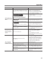
Using the STUDIO-CAPTURE . . . .60
Problems When Two Units Are
Connected . . . . . . . . . . . . . . . . . . . . .66
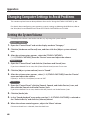
Changing Computer Settings to
Avoid Problems . . . . . . . . . . . . . . . . . . . . . .68
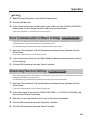
Setting the System Volume . . . . . 68
Voice Communication
Software Settings . . . . . . . . . . . . . .69
Monitoring Function Settings . . .69
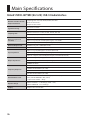
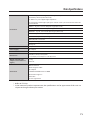
Main Specications . . . . . . . . . . . . . . . . . . . . 70
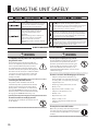
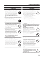
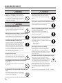
USING THE UNIT SAFELY . . . . . . . . . . . . . . . . 72
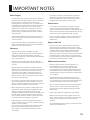
IMPORTANT NOTES . . . . . . . . . . . . . . . . . . . . 75
Index . . . . . . . . . . . . . . . . . . . . . . . . . . . . . . . . . . 77
Contents

3
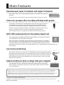
Simultaneously input 16 channels and output 10 channels
At 96/48/44.1 kHz, you can simultaneously input 16 channels and output 10
channels.
This allows you to use multi-mic setups to record acoustic drums or a band.
Twelve mic preamps allow recording with high audio quality
The STUDIO-CAPTURE comes equipped with twelve of the highly acclaimed
“VS PREAMP” mic preamps, which were designed to provide the highest
possible sound quality when they were introduced on the OCTA-CAPTURE.
Despite its compact body, the STUDIO-CAPTURE can capture the true sound
of your instruments and mics with astoundingly high audio quality.
A wide range of inputs are supported, and you can also connect a guitar.
AUTO-SENS automatically sets the optimal input level
The analog input jacks oer AUTO-SENS, which analyzes an instrument’s volume
and automatically sets the optimal input level.
After AUTO-SENS is turned ON, the input signal’s volume changes are analyzed
during a rehearsal for a xed length of time, allowing the signal to be recorded on
your DAW software at the optimal level. This is convenient for recording sessions
with limited setup time, and lets you avoid problems such as clipping due to inappropriate input
level settings.
Low-latency monitoring
The STUDIO-CAPTURE uses the same “VS STREAMING” audio streaming technology
that won broad acclaim when it was introduced on the OCTA-CAPTURE. Thanks to a
high degree of fusion between the driver and the hardware, we have been able to
keep monitoring latency during recording to an ultra-low level, and ensure stable
operation for the system.
Dedicated software allows settings from your computer
The dedicated “STUDIO-CAPTURE Control Panel” software lets you edit all of
the parameters. (Parameters not shown in the display of the STUDIO-CAPTURE
can also be edited.)
Main Features
Before using this unit, carefully read the sections entitled “USING THE UNIT SAFELY” (p. 72) and “IMPORTANT
NOTES” (p. 75). These sections provide important information concerning the proper operation of the unit.
Additionally, in order to feel assured that you have gained a good grasp of every feature of your new unit, read
Owner’s Manual in its entirety. This manual should be saved and kept on hand as a convenient reference.
Copyright © 2013 ROLAND CORPORATION
All rights reserved. No part of this publication may be reproduced in any form without the written permission of
ROLAND CORPORATION.

4
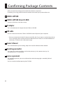
After you open the package, please check that all items are present.
If anything is missing, please contact the retailer from whom you purchased the unit.
STUDIO-CAPTURE
STUDIO-CAPTURE Driver CD-ROM
Contains USB drivers, and demo songs.
AC adaptor
This is the dedicated AC adaptor for the STUDIO-CAPTURE.
USB cable
Use this cable to connect the STUDIO-CAPTURE to the USB port of your computer.
* Please use only the included AC adaptor and USB cable. If you require a replacement due to
loss or damage, please contact the nearest Roland Service Center, or an authorized Roland
distributor, as listed on the “Information” page.
Owner’s Manual
This is the document you’re reading. Keep it on hand for reference when needed.
Block Diagram leaet
This shows the audio signal ow, and how the preamp (p. 30), monitor mixer (p. 32),
and patch bay (p. 37) are related.
License agreement
This agreement permits you to use software for which the copyright is owned by Roland
Corporation.
You must read this before opening the CD-ROM.
Conrming Package Contents

Conrming Package Contents
5
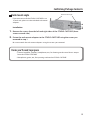
Rack mount angle
If you want to install the STUDIO-CAPTURE in an
19-inch rack, please use the included rack mount
adaptors.
Installation
1. Remove the screws from the left and right sides of the STUDIO-CAPTURE (three
screws on each side).
2. Fasten the rack mount adaptors to the STUDIO-CAPTURE using the screws you
removed in step 1.
Be sure to attach the rack mount adaptors using the screws you removed.
Items you’ll need to prepare
• External amplier, speakers, headphones, etc., for listening to the sound that is output
from the STUDIO-CAPTURE
• Microphone, guitar, etc., for inputting audio to the STUDIO-CAPTURE
Rack mount angle

6
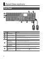
Front Panel
3
4 5
6 7 8
1
2
Number Name Explanation
1
Input level meters
These indicate the input levels of the 16 channels. Adjust the input level so
that the peak indicator (0; red LED) of each input level meter does not light.
2
Input channel indicators
These indicate the selected channel. You can edit the preamp settings of the
channel whose indicator is lit.
3
Input channel buttons
Press the button of the input channel for which you want to edit preamp,
compressor, or attenuator settings (p. 19, p. 22).
4
Display This shows various information about the STUDIO-CAPTURE.
[VALUE] knob
([MENU] button)
Turn this knob to edit the parameter value.
If you press this knob, the SYSTEM screen (p. 43) appears in the display.
[DISPLAY] button The main screen (p. 18) appears in the display.
Cursor [
] [ ]
[
] [ ] buttons
These buttons move the cursor in the display.
5
MONITOR OUT level meter
This indicates the level of the audio signal immediately before the [MONI-
TOR OUT LEVEL] knob (refer to the separate “Block Diagram“ leaet).
[
] (Power) button
To turn the power on/o, hold down the [ ] (power) button for several
seconds (p. 16).
Panel Descriptions

Panel Descriptions
7
Number Name Explanation
6
Here you can make settings for the preamp and compressor of the input channel whose input channel
indicator is lit (p. 19–p. 22).
[SENS] knob Adjusts the preamp gain of the input channel (p. 20).
[AUTO-SENS] button Automatically sets the level optimally for the audio input signal (p. 20).
[PHASE] button Inverts the polarity of the audio input signal (p. 20).
[LoCUT] button Applies a low-cut lter to the audio input signal (p. 20).
[48V] button
Supplies phantom power to the input channel (p. 20). Turn this on if phantom
power is required, such as when a condenser mic is connected.
[COMPRESSOR] button Applies a compressor to the audio input signal (p. 22).
[THRESHOLD] knob Adjusts the level at which the compressor is applied (p. 22).
GR indicator This will light when the compressor is being applied.
7
[DIRECT MONITOR] knob
Adjusts the level of the audio signal that is output from the input channel
mixer (DIRECT MONITOR; refer to the separate “Block Diagram“ leaet).
[MONITOR OUT LEVEL]
knob
Adjusts the level of the audio signals that are output from MONITOR OUT
1L and 2R (LINE OUT 1L and 2R jacks) (refer to the separate “Block Diagram“
leaet).
8
[PHONES LEVEL 1],
[PHONES LEVEL 2] knobs
The [PHONES LEVEL 1] and [PHONES LEVEL 2] knobs adjust the level of the
audio signals that are output from the PHONES 1 and 2 jacks, respectively.
PHONES 1, 2 jacks You can connect headphones to these jacks.
* The explanations in this manual include illustrations that depict what should typically be
shown by the display. Note, however, that your unit may incorporate a newer, enhanced
version of the system (e.g., includes newer sounds), so what you actually see in the display may
not always match what appears in the manual.

Panel Descriptions
8
INPUT 1–12 jacks
These are analog audio input jacks equipped with mic preamps. Either balanced or unbalanced sources can be
connected.
Guitar
Bass
Connect to either INPUT 1 or 2, and turn Hi-Z on (p. 20).
Condenser microphone
Connect using a balanced (XLR) plug and turn on the [48V] button
(p. 20).
(Phantom power is not supplied to phone plugs.)
Dynamic microphone
Turn o the [48V] button (p. 20) and connect using a balanced (XLR)
plug.
* The [48V] button must be turned o.
* You must use an XLR plug when connecting a mic.
Howling could be produced depending on the location of microphones relative to speakers. This can be
remedied by:
1. Changing the orientation of the microphone(s).
2. Relocating microphone(s) at a greater distance from speakers.
3. Lowering volume levels.

Panel Descriptions
9
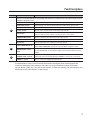
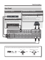
Rear Panel
INPUT 13–16 jacks
These are analog audio input jacks. Either bal-
anced or unbalanced sources can be connected.
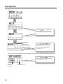
This instrument is equipped with balanced (XLR/TRS) type jacks. Wiring diagrams for these jacks are shown
below. Make connections after rst checking the wiring diagrams of other equipment you intend to connect.
1: GND2: HOT
3: COLD
1: GND 2: HOT
3: COLD
TIP: HOT
RING: COLD
SLEEVE: GND
INPUT 1–12 jacks MONITOR OUT 1L, 2R jacks
MONITOR OUT 1L, 2R jacks
Connect a mixer or other device here.
[MONITOR OUT LEVEL] switch
If this is “ON,” the [MONITOR OUT LEVEL] knob
7
will be
enabled.
If this is set to “BYPASS,” the audio signal unaected by the
[MONITOR OUT LEVEL] knob will be output.
For details, refer to the separate “Block Diagram” leaet.
COAXIAL IN (15/16) jack
Here you can connect a device that is able to
transmit digital audio signals. Alternatively, you
can connect an additional STUDIO-CAPTURE unit
(p. 46).

Panel Descriptions
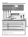
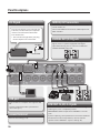
10
DC IN jack
Connect the included AC adaptor.
AC Outlet
Power Cord
Place the AC adaptor so the side with the
indicator (see illustration) faces upwards
and the side with textual information
faces downwards.
* The indicator will light when you plug
the AC adaptor into an AC outlet.
USB port
Connect this to a computer that supports USB
2.0.
Install the USB driver before you make this
connection (p. 11).
LINE OUT 1L, 2R, 3–8 jacks
Connect these to devices that are able to receive analog
audio signals, such as amplied speakers.
MONITOR OUT will be output to the LINE OUT 1L and 2R
jacks.
If you’re capturing a band performance and want a dierent
monitor balance for each performer, connect monitor
speakers to the LINE OUT 3–8 jacks as well (p. 45).
MIDI IN, OUT connectors
Connect the MIDI OUT connector to an external MIDI
sound module, etc.
Connect the MIDI IN connector to a MIDI keyboard or
MIDI controller.
COAXIAL OUT (9/10) jack
Connect a device that is able to receive digital audio
signals, such as a speaker equipped with digital
input. Alternatively, you can connect an additional
STUDIO-CAPTURE unit (p. 46).
Ground terminal
Refer to “Grounding” (p. 76).

11
USB Driver Installation
A USB driver is software installed on your computer that handles data sent between your
computer’s software and the STUDIO-CAPTURE.
In order to use the STUDIO-CAPTURE with a computer, the USB driver must be installed.
NOTE
Do not connect the STUDIO-CAPTURE to the computer until you are directed to do so.
MEMO
Refer to the Roland website for the latest USB drivers and information about compatibility with
the latest operating system versions.
http://www.roland.com/support/
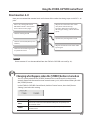
Install the USB Driver (Windows)
1. Connect the AC adaptor (p. 10).
2. Start up the computer without the STUDIO-CAPTURE connected.
Exit all applications that are running.
Windows 8
Switch to the “Desktop.”
3. Insert the included “STUDIO-CAPTURE Driver CD-ROM” into the DVD-ROM drive.
4. Double-click the [Setup] icon in the [WinDriver] folder on the CD-ROM.
The installer starts.
5. Follow the instructions on the screen and install the software.
5-1.
When a conrmation screen regarding user account control appears, click the [Yes] button
or [Continue] button.
5-2. When “The STUDIO-CAPTURE Driver will be installed on your computer.” appears, click the
[Next] button.
5-3. Click the [Next] button again.
MEMO
• If a dialog box regarding Windows security appears, click the [Install] button.
• If the “Software Install” dialog box appears, click the [Continue] button.

USB Driver Installation
12
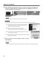
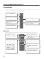
6. When “Ready to install the driver.” appears, connect the STUDIO-CAPTURE to the
computer using the USB cable, and then hold down the [ ] (power) button for
several seconds to turn on the power.
MEMO
If a message appears, follow the instructions on the screen.
Windows XP
If using Windows XP, follow the instructions on the screen and continue the installation.
6-1. If a dialog box that asks whether you want to connect to
Windows Update appears, select the [No, not this time]
button and click the [Next] button.
6-2. Select the [Install the software automatically
(Recommended)] button and click the [Next] button.
6-3. If the “Hardware Installation” dialog box appears, click the
[Continue Anyway] button.
6-4. When “Completing the Found New Hardware Wizard” appears,
click the [Finish] button.
7. When “Installation has been completed.” appears, click the
[Close] button.
The installer exits.
MEMO
If the “Change System Settings” dialog box appears, click the [Yes] button. Windows restarts.

USB Driver Installation
13
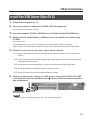
Install the USB Driver (Mac OS X)
1. Connect the AC adaptor (p. 10).
2. Start up the computer without the STUDIO-CAPTURE connected.
Exit all applications that are running.
3. Insert the included “STUDIO-CAPTURE Driver CD-ROM” into the DVD-ROM drive.
4. Double-click the [StudioCapture_USBDriver] icon in the [MacDriver] folder on the
CD-ROM.
The installer starts.
If a dialog box requesting a password appears during installation, enter a computer
administrator’s user name and password and click the [Install Software] button or [OK] button.
5. Follow the instructions on the screen and install the software.
5-1.
When “Welcome to the STUDIO-CAPTURE Driver installer” appears, click the [Continue]
button.
5-2. If the screen for selecting the installation destination appears, select the startup disk and
click the [Continue] button.
5-3. When the installation type appears, click the [Install] button or [Upgrade] button.
5-4. Click the [Continue Installation] button in the next screen.
5-5. When installation has nished, click the [Restart] button.
6. Once your computer has started, use a USB cable to connect the STUDIO-CAPTURE
to the computer, and then hold down the [
] (power) button for several seconds to
turn on the power.
MEMO
Refer to “Mac OS X MIDI Settings” (p. 56) if you intend to use MIDI.

USB Driver Installation
14
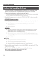
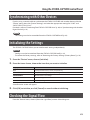
Conrm that Sound Can Be Heard
Congure the computer so that audio played from a program that uses the computer’s audio
features, such as Music (Windows 8 app), Windows Media Player or iTunes, can be heard.
1. Connect the headphones or amplied speakers (p. 7, p. 10).
* To prevent malfunction and equipment failure, always turn down the volume, and turn o all
the units (except the computer) before making any connections.
2. Use the following procedure to select the “STUDIO-CAPTURE” as the system audio
output device.
Windows 8/Windows 7/Windows Vista
2-1. Open the “Control Panel,” click the [Hardware and Sound] icon, and then click the [Sound]
icon. If you have selected Icon view or Classic view, double-click the [Sound] icon.
2-2. Click the [Playback] tab, select the STUDIO-CAPTURE’s [1–2], and then click the
[Set Default] button.
2-3. Click the [OK] button.
Windows XP
2-1. Open the “Control Panel,” click the [Sounds, Speech, and Audio Devices] icon, and then
double-click the [Sounds and Audio Devices] icon. If you have selected Classic view,
double-click the [Sounds and Audio Devices] icon.
2-2. Click the [Audio] tab and select [1–2 (STUDIO-CAPTURE)] in the [Sound playback] area.
When connecting the external MIDI sound module, select [STUDIO-CAPTURE] in the [MIDI
music playback] area.
2-3. Click the [OK] button.
Mac OS X
2-1. Open “System Preferences” and click the [Sound] icon.
2-2. Click the [Output] tab and select [STUDIO-CAPTURE].
2-3. When you have nished making these settings, quit “System Preferences.”
3. Open the folder named [Sample] on the included CD-ROM, and copy the le “TTears
(.mp3)” to the desktop.
4. Double-click the le “TTears (.mp3)” that you copied to the desktop.
Music (Windows 8 app), Windows Media Player or iTunes starts.
Click the playback button to play the sample le.

USB Driver Installation
15
MEMO
• The software that starts and is used to play the sample le may vary depending on your
computing environment. If dierent software starts, play the sample le as described in the
owner’s manual for the software you are using.
• If you cannot select “STUDIO-CAPTURE” in step 2-2, refer to “Using the STUDIO-CAPTURE“ (p. 60).
• If the STUDIO-CAPTURE is selected as the output device, the computer’s audio alerts will be
played using the STUDIO-CAPTURE; they will not be heard from the computer’s speakers.
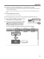
To open the Control Panel
Windows 8
1. On the Start screen, click the Desktop.
2. Move the mouse pointer to the upper right or lower right corner of the screen
to display the charms.
* On touch-enabled PCs, swipe from the right side of the screen to display the charms.
3. Click [Settings] and display the “Settings charms.”
4. In “Settings charms,” click [Control Panel] to open the “Control Panel.”

16
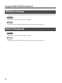
Basic Operation
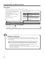
Connecting Equipment
Connect guitars and mics to the INPUT jacks, and amplied speakers to the LINE OUT 1L and 2R
jacks. Headphones can be connected to the PHONES 1 jack and PHONE 2 jack (p. 6–p. 10).
Turning the Power On/O
* Before you proceed, you must install the USB driver on your computer (p. 11).
* Once everything is properly connected (p. 6–p. 10), be sure to follow the procedure below to turn
on their power. If you turn on equipment in the wrong order, you risk causing malfunction or
equipment failure.
Turning the Power On
1. Turn the [MONITOR OUT LEVEL] knob and [PHONES LEVEL 1] [PHONES LEVEL 2]
knobs all the way to the left.
2. Connect the STUDIO-CAPTURE to the computer using the USB cable.
3. Switch on the power to any external equipment connected to the input jacks.
4. Press and hold the STUDIO-CAPTURE’s [ ] (Power) button for several seconds, and
then release it.
* This unit is equipped with a protection circuit. A brief interval (a few seconds) after turning the
unit on is required before it will operate normally.
* Before turning the unit on/o, always be sure to turn the volume down. Even with the volume
turned down, you might hear some sound when switching the unit on/o. However, this is
normal and does not indicate a malfunction.
5. Switch on the power to your amp or powered monitor speakers.
6. During playback, adjust the volume by turning the [MONITOR OUT LEVEL] knob and
[PHONES LEVEL 1] [PHONES LEVEL 2] knobs toward the right.

Basic Operation
17
Turning the Power O
Before you turn o the power, make sure to do the following.
• Turn the [MONITOR OUT LEVEL] knob and [PHONES LEVEL 1] [PHONES LEVEL 2] knobs all the
way to the left
• Minimize the volume of all connected equipment
1. Switch o the power to your amp or powered monitor speakers.
2. Press and hold the STUDIO-CAPTURE’s [ ] (Power) button for several seconds, and
then release it.
The next time you turn the power on, the unit will start up with the settings that were in eect
when it was powered o.
3. Switch o power to the connected equipment.
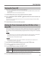
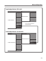
Making the Power Automatically Turn O After a Time
(Auto O)
When not connected to a computer, the STUDIO-CAPTURE will automatically be switched o four
hours after you stop playing or operating it (if the factory settings have been unmodied). If you
don’t want the unit to turn o automatically, change the “AUTO-OFF” setting to “OFF” as described
below.
NOTE
• Any settings that you are in the process of editing will be lost when the power is turned o. If
you have any settings that you want to keep, you should save them beforehand.
• To restore power, turn the power on again.
MEMO
Auto O will not function if the STUDIO-CAPTURE is connected to your computer, or if a
microphone/instrument is connected.
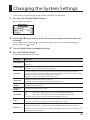
1. Press the [VALUE] knob ([MENU] button) to access the SYSTEM screen.
2. Use the [ ] [ ] buttons to choose “AUTO-OFF.”
3. Turn the [VALUE] knob to choose “4HOURS” or “OFF.”
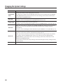
Value Explanation
OFF The power will not turn o automatically.
4HOURS
(default)
When not connected to a computer/microphone/instrument, the STUDIO-CAPTURE will
automatically be switched o four hours after you stop operating it.
4. Press the [DISPLAY] button to return to the main screen (p. 18).

Basic Operation
18
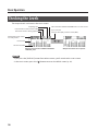
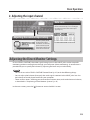
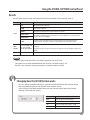
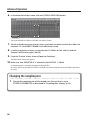
Checking the Levels
The output levels are shown in the main screen.
[ ]
[ ]
Output level from the STUDIO-CAPTURE’s
LINE OUT jacks
Output level from the computer
Name of the level meters
currently shown
Indicate when connected via USB
Sampling rate
Channel number
Level meter
Sync indicator
Internal clock (INT), External clock (EXT)
Indicate if two STUDIO-CAPTURE units are connected
Indicate if reverb is being applied
MEMO
• If you press the [DISPLAY] button from other screens, you’ll switch to this main screen.
• In the main screen, press the [
] button to access the MIX A screen (p. 24).

Basic Operation
19
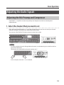
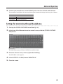
Adjusting the Audio Signals
Adjusting the Mic Preamp and Compressor
Each INPUT 1–12 jack has its own mic preamp and compressor which can be adjusted
independently.
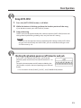
1. Select the channel that you want to set
Press the input channel button (1–12) of the channel that you want to set; the input channel
indicator will light. The display will show the preamp screen.
You can press the [DISPLAY] button to return to the main screen.
MEMO
To select multiple channels (Range Select function), simultaneously press the rst and last
input channel buttons.
The display will show the rst channel number and “-.”
In this example, channels 1–8 are selected.

Basic Operation
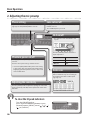
20
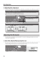
2. Adjusting the mic preamp
Phase setting
If you want to invert the phase of the audio input
signal, press the [PHASE] button so it’s lit.
Low-cut on/o
To apply the low-cut lter, press the [LoCUT]
button so it’s lit.
The cuto frequency is 75 Hz.
Hi-Z on/o
* This function is for the INPUT 1 and
2 jacks.
Turn the [VALUE] knob to switch the
input impedance.
Device Hi-Z
Guitar/Bass On
Mic, etc. O
Auto-sens
If you use AUTO-SENS, the input level
will be automatically set according to
the highest level of the audio input
signal (p. 21).
Adjusting the sensitivity
Turn the [SENS] knob to adjust the input gain so that the
peak indicator (0; red LED) of the input level meter does
not blink.
Phantom power on/o
To supply phantom power, press the [48V] button
so it’s lit.
Turn this on if you’re using a condenser mic.
* Leave the [48V] button o if you’re connecting
a device that does not support phantom power.
Supplying phantom power to such a device will
cause malfunction.
To clear the lit peak indicators
Turn the [VALUE] knob or
press any of the following buttons: input
channel buttons, [MENU], cursor[ ] [ ] [ ]
[ ], or [DISPLAY].
Page is loading ...
Page is loading ...
Page is loading ...
Page is loading ...
Page is loading ...
Page is loading ...
Page is loading ...
Page is loading ...
Page is loading ...
Page is loading ...
Page is loading ...
Page is loading ...
Page is loading ...
Page is loading ...
Page is loading ...
Page is loading ...
Page is loading ...
Page is loading ...
Page is loading ...
Page is loading ...
Page is loading ...
Page is loading ...
Page is loading ...
Page is loading ...
Page is loading ...
Page is loading ...
Page is loading ...
Page is loading ...
Page is loading ...
Page is loading ...
Page is loading ...
Page is loading ...
Page is loading ...
Page is loading ...
Page is loading ...
Page is loading ...
Page is loading ...
Page is loading ...
Page is loading ...
Page is loading ...
Page is loading ...
Page is loading ...
Page is loading ...
Page is loading ...
Page is loading ...
Page is loading ...
Page is loading ...
Page is loading ...
Page is loading ...
Page is loading ...
Page is loading ...
Page is loading ...
Page is loading ...
Page is loading ...
Page is loading ...
Page is loading ...
Page is loading ...
Page is loading ...
Page is loading ...
Page is loading ...
-
 1
1
-
 2
2
-
 3
3
-
 4
4
-
 5
5
-
 6
6
-
 7
7
-
 8
8
-
 9
9
-
 10
10
-
 11
11
-
 12
12
-
 13
13
-
 14
14
-
 15
15
-
 16
16
-
 17
17
-
 18
18
-
 19
19
-
 20
20
-
 21
21
-
 22
22
-
 23
23
-
 24
24
-
 25
25
-
 26
26
-
 27
27
-
 28
28
-
 29
29
-
 30
30
-
 31
31
-
 32
32
-
 33
33
-
 34
34
-
 35
35
-
 36
36
-
 37
37
-
 38
38
-
 39
39
-
 40
40
-
 41
41
-
 42
42
-
 43
43
-
 44
44
-
 45
45
-
 46
46
-
 47
47
-
 48
48
-
 49
49
-
 50
50
-
 51
51
-
 52
52
-
 53
53
-
 54
54
-
 55
55
-
 56
56
-
 57
57
-
 58
58
-
 59
59
-
 60
60
-
 61
61
-
 62
62
-
 63
63
-
 64
64
-
 65
65
-
 66
66
-
 67
67
-
 68
68
-
 69
69
-
 70
70
-
 71
71
-
 72
72
-
 73
73
-
 74
74
-
 75
75
-
 76
76
-
 77
77
-
 78
78
-
 79
79
-
 80
80


Ask a question and I''ll find the answer in the document
Finding information in a document is now easier with AI
Related papers
-
Roland SYSTEM-500 512 Owner's manual
-
Roland TD-30 Owner's manual
-
Roland Quad-Capture Owner's manual
-
Roland UA-4FX2 Owner's manual
-
-
Roland CD-Rack Owner's manual
-
-
-
-
Roland UA-5 Owner's manual
Other documents
-
Zoom U-24 Operating instructions
-
PRESONUS AudioBox 1818VSL Quick start guide
-
PRESONUS StudioLive RM32AI Owner's manual
-
PRESONUS StudioLive AVB 48AI Mix System Owner's manual
-
Steinberg UR44C Operating instructions
-
-
PRESONUS StudioLive AR16c Owner's manual
-
-
-
PRESONUS StudioLive 16.0.2 Owner's manual