Page is loading ...

DU 870/871
Owner’s Manual/ Mounting Instructions
After market Kit for Ducati Multistrada 1200

Öhlins Racing AB - The Story
It was the 1970’s, a young man named Kenth
Öhlin spent most of his spare time pursuing his
favourite sport: motocross.
Being a careful observer, Kenth’s attention was
continuously drawn to one specic detail - moto
-
cross bikes had more engine power than their
suspension could handle. It was not long before
Kenth realised that better performance could be
achieved by improved wheel suspension.
Öhlins Racing was established in 1976, and
just two years later the company won its rst
World Championship title. Despite being in the
business for 35 years, the search for perfection
and new functions is still the main focus of the
company.
Congratulations! You are now the owner of an
Öhlins product. More than two hundred World
Championships and other major world titles are
denitive proof that Öhlins suspension offers
outstanding performance and reliability.
Every product has gone through rigorous test
-
ing and engineers have spent thousands of
hours, doing their very best to use every possi
-
ble experience from our 35 years within the rac-
ing sport.
The product that you now have in your pos
-
session is pure racing breed that is built to
withstand.
By installing this product on your vehicle you
have made a clear statement… you are a seri
-
ous rider with a focus on getting the maximal
handling ability and outstanding feedback from
your vehicle. Along comes the fact that your
shock absorber will be a long lasting friend,
delivering the very best of comfort and perfor
-
mance every time you go for a ride. Go explore!
Öhlins Headquarters Upplands Väsby, Sweden

3
BEFORE YOU BEGIN
TABLE OF CONTENTS
Kit Contents
Description Part No Pcs
Shock absorber DU869 1
Front fork FG868 1
Sticker Mechatronic Syst. 00191-46 2
Tie rap 00231-01 20
Sticker Öhlins 01185-01 2
Setting card 01199-01 1
Screw M5x12 04757-10 4
Wire harness 21770-04 1
Electr. tap conn.22-16 AWG 21310-01 1
Fender bracket 21644-02 2
Bracket - preload adj. 21869-01 1
Screw - preload adj. 21869-02 2
Rubber - preload adj. 21869-03 2
Rubber bracket SCU 21869-04 1
SCU 35000-02 1
Dashboard 35007-02 1
Warning!⚠
Before installing this product, read the Safety Precautions
and the information in this manual thoroughly. The shock
absorber/front fork/steering damper is an important part of
your vehicle and will affect the stability.
Note!1
Before installing this product, check the contents of the kit. If
anything is missing, please contact an Öhlins dealer.
SAFETY PRECAUTIONS ..................................................................................4
1 DESIGN ..........................................................................................................5
2 MOUNTING INSTRUCTIONS .........................................................................6
2.1 Before you begin ......................................................................................6
2.2 Install the Öhlins Front Fork .....................................................................6
2.3 Install the Öhlins Shock Absorber .............................................................7
2.4 Install the SCU .........................................................................................9
2.5 Install the Öhlins Dashboard ....................................................................9
2.6 Install the Wire Harness ...........................................................................10
2.7 Install the Electrical Tap Connector ..........................................................11
2.8 After Installation ........................................................................................11
3 SPRING PRELOAD ........................................................................................12
4 DASHBOARD USER GUIDE ..........................................................................13
4.1 Introduction ..............................................................................................13
4.2 Screen navigation.....................................................................................14
4.3 Calibrate Spring Preload ..........................................................................14
4.4 Dashboard Menus ...................................................................................15
4.5 Load Mode ...............................................................................................16
4.6 Recommended Settings ...........................................................................16
4.7 Settings Menu ..........................................................................................17
5 INSPECTION AND MAINTENANCE ..............................................................18

4
General Warnings
Note!1
The shock absorber/front fork/steering damper is an impor-
tant part of the vehicle and will affect the stability.
Note!1
Read and ensure you understand the information in this
manual and other technical documents provided by Öhlins,
before using the product.
Note!1
Öhlins Racing AB can not be held responsible for any dam-
age to the shock absorber/front fork/steering damper, vehi-
cle, other property or injury to persons, if the instructions for
mounting, usage and maintenance are note followed exactly.
Warning!⚠
After installing the Öhlins product, take a test ride at low
speed to ensure your vehicle has maintained stability.
Warning!⚠
If the suspension makes an abnormal noise, or the function
is irregular, or if you notice any leakage from the product,
stop the vehicle immediately and return the product to an
Öhlins dealer.
Warning!⚠
The product warranty shall only apply if the product has
been operated and maintained in accordance with rec
-
ommendations in this manual. If you have any questions
regarding usage, service, inspection and/or maintenance
please contact Öhlins.
Note!1
When working with the Öhlins product, always read the vehi-
cle service manual.
Note!1
This manual shall be considered as a part of the product and
shall accompany the product throughout its life cycle.
SAFETY PRECAUTIONS
© Öhlins Racing AB. All rights reserved.
Any reprinting or unauthorized use without the written
permission of Öhlins Racing AB is prohibited.
SAFETY SYMBOLS
In this manual, mounting instructions and other techni-
cal documents, important information concerning safety is
distinguished by the following symbols:
The Safety Alert Symbol means: Warning! Your safety
is involved.
Warning!⚠
The Warning Symbol means: Failure to follow warning
instructions can result in severe or fatal injury to anyone
working with, inspecting or using the shock absorber, or
to bystanders.
Caution!✋
The Caution Symbol means: Special precautions must be
taken to avoid damage to the shock absorber.
Note!1
The Note Symbol indicates information that is important
regarding procedures.
Product Specic Warnings
Warning!⚠
This product was developed and designed exclusively for
a specic vehicle model and shall only be installed on the
intended vehicle model in its original condition as delivered
from the vehicle manufacturer.

5
1 DESIGN
Congratulations on your purchase of the After
market Kit for Ducati Multistrada 1200 and thank
you for choosing Öhlins Suspension Technology.
The system by Öhlins consists of a TTX shock
absorber, NIX front fork, dashboard, SCU and a
wire harness. This electronically controlled (EC)
system merges smart functions such as pre
programmed riding modes with different damping
characteristics to suit your speed and riding
behaviour.
The TTX EC Concept
The possibility to adjust damping settings dur
-
ing travel has been somewhat of a dream. Now
Öhlins Racing has solved the problem with the
TTX EC concept, also called Mechatronics. Well
tested algorithms control the damper settings
depending on, for instance, the speed.
You can change damper settings on the dash
-
board while riding thanks to the micro-control-
ler in combination with the stepper motor. Like
a remote control that controls the rebound and
compression settings on the shock absorber and
front fork.
The EC Software
The EC software from Öhlins provides different
riding modes for the rider.
The Suspension Control Unit (SCU)
Öhlins SCU is a compact electronic control unit
designed for embedded real time suspension
control applications. It controls several step
-
per motors and one DC motor with position
feedback.
The TTX EC Shock Absorbers
The TTX is a twin tube shock absorber and
always has a positive damping pressure build
up, it is therefore ideal to equip with EC adjust
-
ers. In other words, the pressure is always
raised to create damping, independently of how
the bleed is adjusted. Nitrogen pressure can
then be low, which gives low friction. The adjust
-
ment range is wide for both compression and
rebound damping, you set the adjusters from the
Öhlins dashboard.
The Preload Adjuster EC
The preload adjuster EC is a light and tiny unit
that offers superior performance versus size
ratio. It is a traditional remote hydraulic preload
adjuster but with a DC motor adjusting the
spring preload controlled by the Öhlins SCU,
instead of a manually operated adjuster. The
system also provides information of the preload
position to get optimum setup for different condi
-
tions and circumstances, for example when hav-
ing a passenger and/or luggage.
The Front Fork EC System
In an EC-adjusted front fork the adjustment
needle is activated by an electrical stepper
motor. Control the EC-motors from the Öhlins
dashboard.

6
2 MOUNTING INSTRUCTIONS
2.1 Before you begin
Warning!⚠
It is advisable to have an Öhlins dealer install the shock
absorber/front fork/steering damper.
Warning!⚠
If working on a raised vehicle, ensure it is securely sup-
ported so that it will not tip.
Mounting Instructions
2.1 Before you begin .................................................................6
2.2 Install the Öhlins Front Fork ................................................ 6
2.3 Install the Öhlins Shock Absorber ....................................... 7
2.4 Install the SCU .................................................................... 8
2.5 Install the Öhlins Dashboard ............................................... 8
2.6 Install the Wire Harness ...................................................... 10
2.7 Install the Electrical Tap Connector ..................................... 11
2.8 After Installation ..................................................................11
Note!1
Before mounting this product clean the vehicle thoroughly.
Note!1
When working on this product, always see the Vehicle
Service Manual for vehicle specic procedures and impor
-
tant data.
2.2 Install the Öhlins Front Fork
2.2.1
Put the motorcycle on a work stand so that the
rear wheel barely touches the ground.
2.2.2
Remove the front fender.
2.2.3
If ABS-version, remove the ABS sensor from
the left fork bottom.
2.2.4
Remove the brake calipers and the front
wheel.
2.2.5
Remove the original front fork.
2.2.6
Install the Öhlins front fork. Position the fork
leg so that 10 mm of the golden colored outer
tube is visible above the upper triple crown.
Compression fork leg left side
Rebound fork leg right side
10 mm
2.2.6
7
2 MOUNTING INSTRUCTIONS
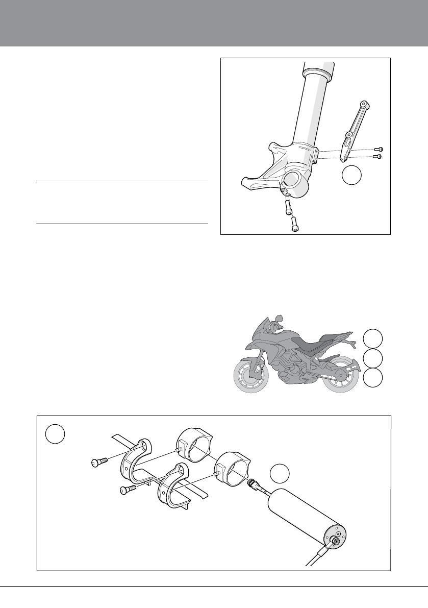
2.2.7
2.2.7
Install the fender brackets (21644-02) with
the screws (04757-10) provided in the kit.
Tightening torque 5-7 Nm. Use thread locking
uid, Loctite 243 or similar on the screws.
2.2.8
Reinstall the wheel, brake calipers, ABS sen
-
sor (if any) and front fender. Tightening torque
according to vehicle service manual.
Note!1
Assemble the four M8-screws clamping the wheel axle to
19Nm torque. Tighten in a 1-2-1 sequence on each side
(1-2-1 sequence: tighten the rst screw, then the other
screw, then nish by tightening the rst screw again).
2.3 Install the Öhlins Shock Absorber
2.3.1
Remove both seats.
2.3.2
Assemble the brackets for the preload adjust
-
er motor according to the gure.
2.3.3
Remove the left panel, below the seat area.
2.3.4
Remove the swing arm fender.
2.3.1
2.3.3
2.3.4
2.3.2
2.3.10
Bracket 21869-01
Preload
adjuster
motor
Screw
21869-02
Rubber
21869-03

8
2 MOUNTING INSTRUCTIONS
2.3.10
2.3.92.3.7
2.3.5
Remove the original preload adjuster.
2.3.6
Remove the lower and upper attachments of
the original shock absorber. Remove the origi
-
nal shock absorber.
2.3.7
Remove the upper left screw to the rear sub
frame.
2.3.8
Install the Öhlins shock absorber. Use the
original screws for the upper and lower attach
-
ments. Compress the suspension slightly
before tightening. Tightening torque according
to vehicle service manual.
2.3.9
Use appropriate tool and carefully bend the
upper left point of the rear sub frame, just
enough to squeeze the preload adjuster hose
between the frame and the rear sub frame.
2.3.10
Install the preload adjuster motor in the rubber
mounts assembled in step 2.
2.3.11
Reinsert the upper left screw to the rear sub
frame. Tightening torque according to vehicle
service manual.
9
2.4 Install the SCU
2.4.1
Insert the Öhlins SCU into the rubber mount
provided with the kit.
2.4.2
Fasten the rubber mount with the SCU on the
left side of the rear sub frame. Use tie raps to
fasten.
2.4.2
2.4.1
2 MOUNTING INSTRUCTIONS
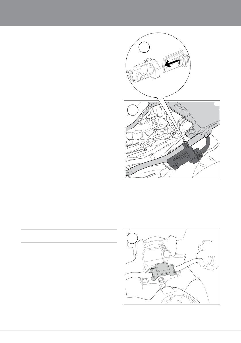
2.5 Install the Öhlins Dashboard
Note!1
Be thorough when fastening the dashboard to the hook
and loop fastener, once attached it will be hard to move.
2.5.1
Fasten the dashboard to the handlebar top
clamp using the supplied hook and loop
fastener.
2.5.1
10
2 MOUNTING INSTRUCTIONS
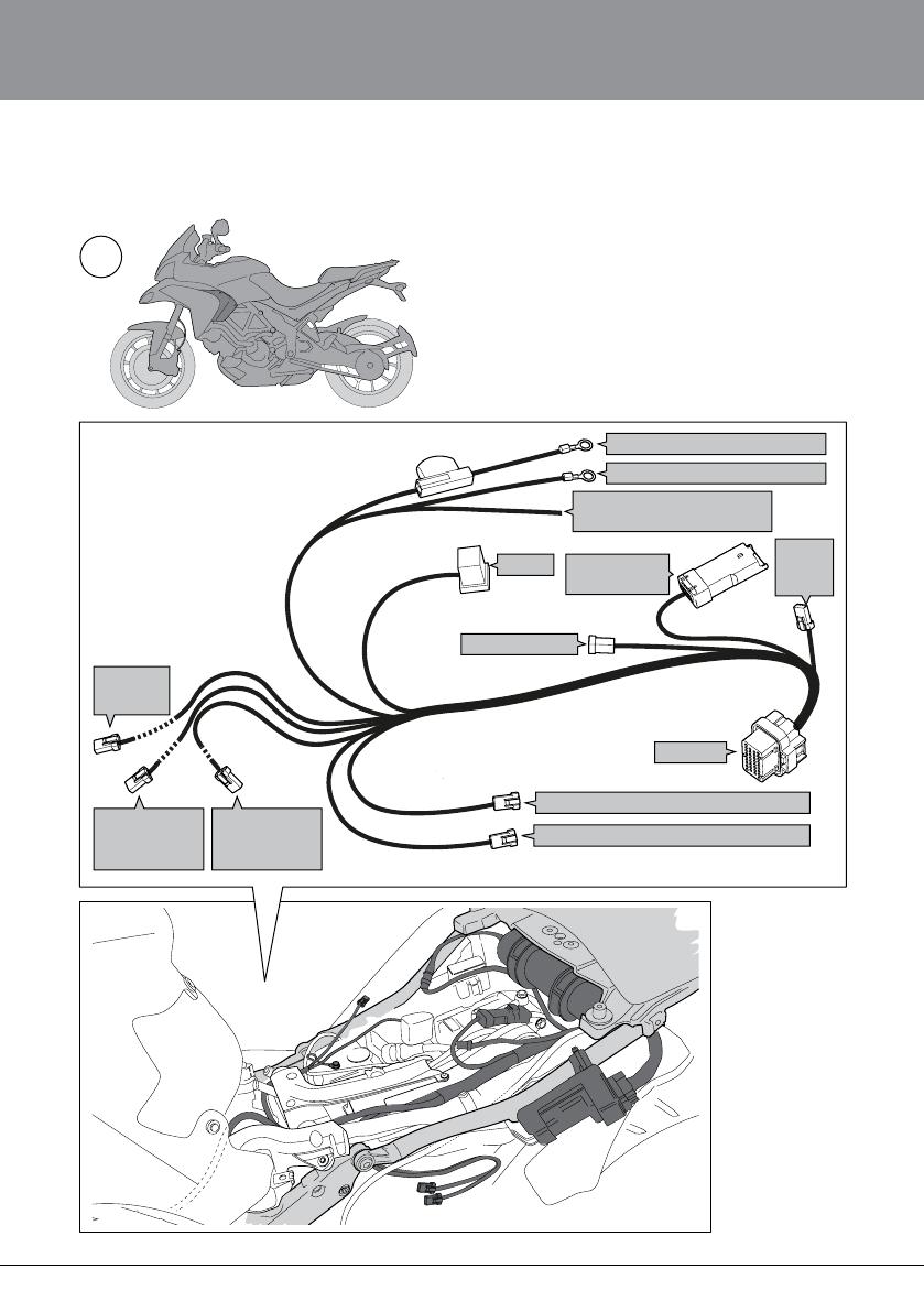
2.6.1
RC to shock absorber, compression (left)
PL to
preload
adjuster
FC to front fork,
compression,
left fork leg
FR to front fork,
rebound,
right fork leg
DB to
dashboard
K1 to battery positive terminal
K2 to battery negative terminal
KO Key On to Electrical tap
Connector (21310-01)
Relay
WH to OEM
wire harness
D Can Diagnose
to SCU
RR to shock absorber, rebound (right)
2.6 Install the Wire Harness
2.6.1
Remove the air deector on the left side.
2.6.2
Connect the connectors/cables, but not K1
and K2 yet, according to the schematic gure.
Note that D shall not be connected.
2.6.3
Fasten the cables with the tie raps provided,
where needed. Ensure that the cables to the
front fork are not stretched, also make sure
not to fasten the cables close to the shock
absorber since the tie raps can prevent the
parts from moving freely.
11
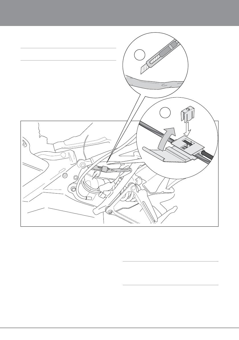
2.7 Install the Electrical Tap Connector
Warning!⚠
Do not perform the following steps with the battery termi-
nals (K1 and K2) connected.
2.7.1
Cut a 30mm incision in the cover of the 12V
power supply outlet cable. Locate the red/blue
cable.
2.7.2
Insert the red/blue cable and the KO cable
according to the gure. Ensure that the KO
cable is inserted until stop.
2 MOUNTING INSTRUCTIONS
2.7.2
2.7.1
2.7.3
Use pliers to gently seal the electrical tap con
-
nector. Ensure that the lid is rmly closed, you
will hear a noticeable click.
2.7.4
Put electrical tape around the cable and the
electric tap connector to protect and to help
them stay in place.
2.8 After Installation
Ensure that all removed parts are reinstalled
according to vehicle service manual.
Caution!✋
Ensure that all screws are tightened to the correct torque
and that nothing fouls or restricts movement of the shock
absorber/front fork/steering damper when the suspension
is fully compressed or extended.

12
3 SPRING PRELOAD
When adjusting the spring preload you move
the spring seat. This will decrease or increase
the initial spring force, which will lower or raise
the motorcycle ride height.
The spring preload is fundamental for the
function of the suspension. If the preload is
incorrectly set, any other adjustments will not
help to get the intended performance from the
suspension.
3.1 Adjust Spring Preload
Front (Front Fork)
1
Disconnect the EC cables.
2
Use a 32 mm wrench. Turn counter clock
-
wise to fully open, position 0. Turn clockwise
and count the turns until you reach the desired
preload.
Recommended Spring Preload
Front fork Spring preload 6 mm
Rear (Shock Absorber)
Adjust spring preload on the dashboard.
13
4 DASHBOARD USER GUIDE
4.1 Introduction
The Öhlins Dashboard features an intuitive
touch screen interface designed to make
navigation easy for everyone. With the dash
-
board the rider can easily switch between
the different suspension characteristics
maps for the three riding modes; urban, tour
-
ing and sport. Within each riding mode you
can then easily change and edit the setup
for the front and rear suspension, brake sup
-
port, speed support and load mode.
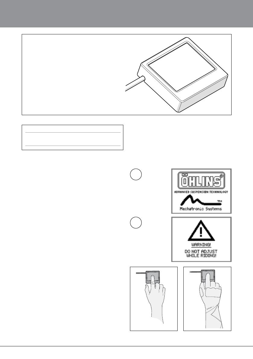
Start Up Screen
Activate the dashboard. The start up (1) and
warning (2) screen light up.
1
2
How to Navigate
Press the touch screen to navigate. Note that
the dashboard also works if wearing a glove.
Note!1
After installation calibrate the spring preload. Go to
chapter 4.3.
14
4 DASHBOARD USER GUIDE
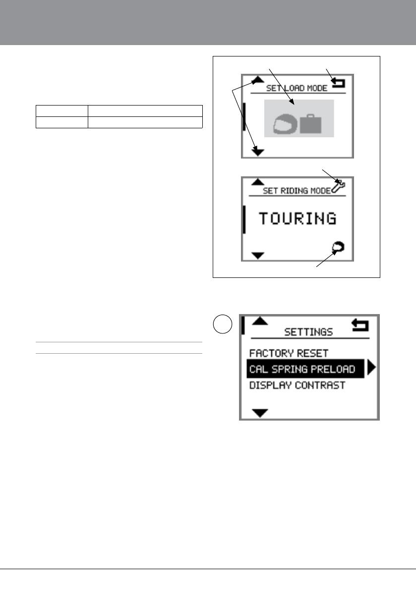
4.2 Screen navigation
A Arrows up/down to navigate in the menu.
B Pressure area.
Short press Toggle within menu
Long press Enter menu to change setting
C Return arrow/ Conrm
D Error indication - Contact Öhlins
E Load mode
4.4.2
4.3 Calibrate Spring Preload
Note!1
After installation always calibrate the spring preload.
4.3.1
Switch the ignition on, and at the same time
press (long press) on the dashboard screen.
The dashboard lights up and the screen
shows SETTINGS menu.
4.3.2
Press the arrows up/down and choose CAL
SPRING PRELOAD.
Press the arrow to the right and the calibration
starts.
4.3.3
After calibration press return arrow to go to
the SETTINGS menu.
4.3.4
Press the return arrow once more to exit the
SETTINGS menu.
A
B C
D
E
15
4.4 Dashboard Menus
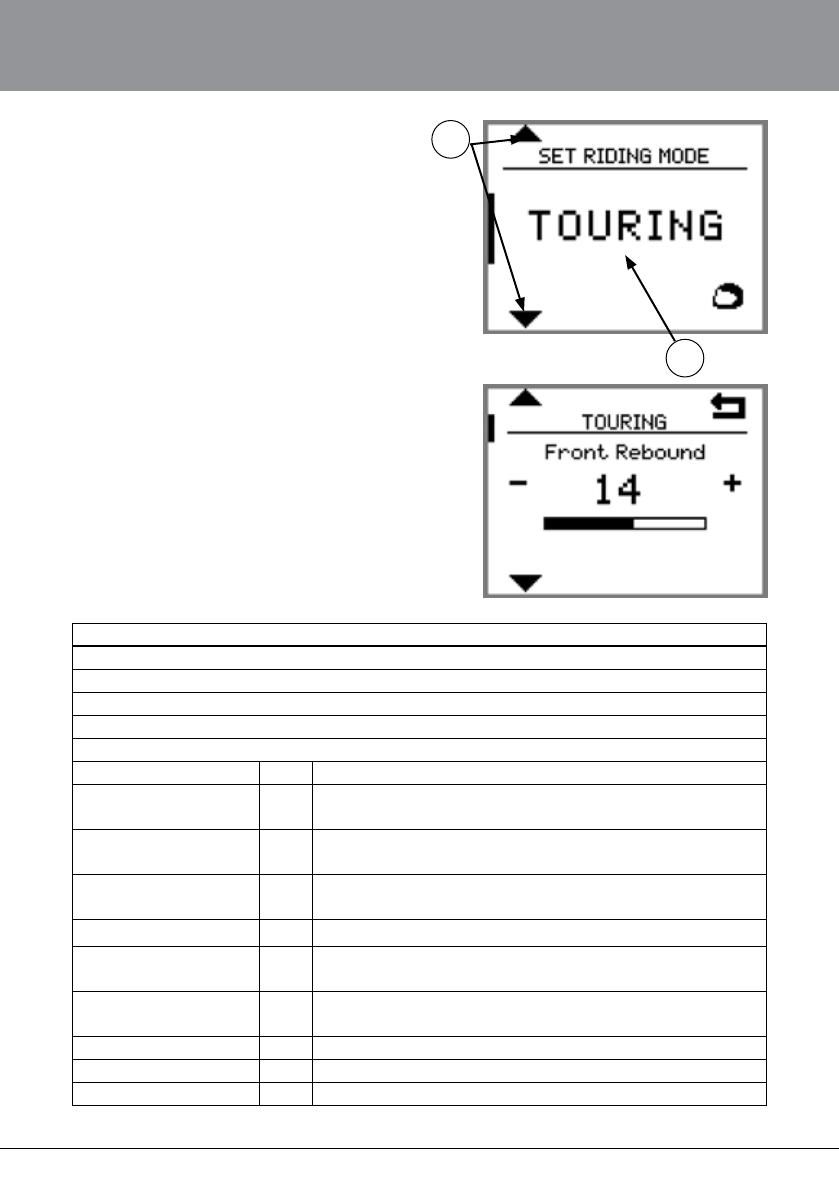
4.4.1 Riding Mode
There are 3 riding modes;
URBAN
TOURING
SPORT
1
2
To change riding mode;
Press the arrows up/down (1) or short press in
the middle of the screen (2) to toggle between
the three modes.
Change setting within a riding mode
Long press in the middle of the screen (on
URBAN, TOURING or SPORT) to enter the
setting in the riding mode.
Press the arrows up/down to toggle between
the different setup selections. Press the return
button to conrm.
4 DASHBOARD USER GUIDE
Setup Selections
Front Compression
Front Rebound
Rear Compression
Rear Rebound
Spring Preload
Speed function OFF No speed function is used
1 Very soft at low speed,
soft at high speed
2 Very soft at low speed,
medium at high speed
3 Medium at low speed,
stiff at high speed
Acceleration function OFF No acceleration function is used
1 Medium grip and
stability optimization
2 Aggressive grip and
stability optimization
Brake function OFF No brake function is used
1 Medium brake optimization
2 Aggressive brake optimization
16
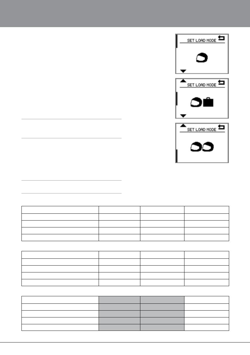
4.5 Load Mode
There are 3 load modes;
Rider only (A)
Rider with luggage (B)
Rider and passenger (C)
To change load mode;
Long press on the load mode symbol.
Navigate between the three load modes with
the arrows up/down or with short press in the
middle of the screen. Press the return button
to conrm and go back to main menu.
Note!1
Load mode only changes preload, adjust settings accord-
ing to the table in chapter 4.6 (or the Setting Card provid-
ed in this kit).
4 DASHBOARD USER GUIDE
Delivery Settings
URBAN TOURING SPORT
Base click settings 24, 24, 24, 24 18, 14, 16, 16 6,10,10,12
Speed function 1 2 Off
Acceleration function Off Off 1
Brake function Off Off 1
Luggage/ Passenger Recommendations
URBAN TOURING SPORT
Base click settings 18,14,16,16 14,14,10,12 6,10,6,12
Speed function 2 3 Off
Acceleration function Off Off 1
Brake function Off Off 1
Track Recommendations
SPORT
Base click settings 2,8,4,8
Speed function Off
Acceleration function 1 or 2
Brake function 1 or 2
A
B
C
4.6 Recommended Settings
Base click settings; Front Compression, Front
Rebound, Rear Compression, Rear Rebound
Note!1
Speed function over rides base click settings. If speed
function is set to off, use base click settings.

17
CAL SPRING PRELOAD Calibrate spring preload. Performed after installation.
DISPLAY CONTRAST Adjust the display contrast (0-100%)
ACTIVE BACKLIGHT Adjust the display backlight in “active mode” (0-100%)
INACTIVE BACKLIGHT Adjust the display backlight in “active mode” (0-100%)
ACTIVE TIMEOUT Adjust the time that the display is active. 0.0 turns of the “inac
-
tive mode” [0.5-60.0 s)
FACTORY RESET Resets all to factory settings.
4.7 Settings Menu
To reach the Settings menu switch the ignition
on and press, long press, the screen.
There are 6 different selections in the settings
menu;
4 DASHBOARD USER GUIDE

18
5 INSPECTION AND MAINTENANCE
Preventive maintenance and regular inspection
reduces the risk of poor performance. If there is
any need for additional service, please contact
Öhlins.
Cleaning
Clean externally with a soft detergent.
Use compressed air. Ensure that all dirt is
removed. Keep the shock absorber/front fork
clean and spray it with oil (WD40, CRC 5-56
or equivalent) after washing. Wipe off exces
-
sive oil with a cloth.
Caution!✋
Never use strong detergents that can damage the surfaces.
Thinner and brake cleaner will dry out seals, increase the
risk of friction, oil leakage or even malfunction. Never spray
water directly into the adjuster knobs and/or ball joints.
Note!1
Öhlins products should only be lled with Öhlins High
Performance Shock Absorber/Front Fork Fluid. Contact
Öhlins for advice.
Warning!⚠
Never alter gas pressure. Special purpose charging
equipment and access to nitrogen is required.
7
2
3
4
1
Inspection points
Shock Absorber
1. Check ball joints for possible excessive play
or stiction.
2. Check the piston shaft for leakage and
damage.
3. Check the shock absorber body for external
damage.
4. Check the reservoir for external damage
that can restrict the oating piston from
moving freely.
5. Check for excessive wear of rubber
components.
6. Check the attachment points of the shock
absorber to the vehicle.
7. Check the electrical wires and connectors
for external wear or damages.
Recommended Service Intervals
Regular street use: Every 30 000 km
Track: Every 10 hours of operation.
Maximum 20 hours of operation
without service and oil change.

19
Front Fork
1. Check for external oil leakage.
2. Check the inner fork leg for scratches, dents
or other defects (that might harm the seal/
bushing).
3. Check fastening of fender brackets and
brake caliper.
4. Check fastening to the vehicle.
Recommended Service Intervals
Regular street use: Once a year or every
5000 km
Race track: Every 10 hours
Once every 2nd year (or 20 000 km)
Change the front fork oil. Remove outer fork
leg and inspect the bushings, seals and the
full length of the inner fork leg. Replace the
seals and bushings if necessary. Proceed
according to Öhlins Workshop manual.
3
4
2
5 INSPECTION AND MAINTENANCE
Your Öhlins retailer:
Phone: +46 (0)8 590 025 00
Fax: +46 (0)8 590 025 80
www.ohlins.com
Öhlins Racing AB
Box 722
SE-194 27, Upplands Väsby
Sweden
Öhlins Owner’s Manual AM Kit DU870/871 | Part No. 07243-01_1 | Issued 2014-09-08 | © Öhlins Racing AB
/