INTRODUCTION
To the owner or user: This manual is intended to
provide you, and the maintenance or service
technician, with the information needed to install,
start up, clean, maintain, and service this ice
system.
This is a modular type ice system that fits a variety
of Scotsman ice storage bins.
Its features include: front service for the freezer,
gear motor, control box, water reservoir, and bin
control; an electronic circuit for monitoring ice and
water level; a thermostatic expansion valve; and
R-404A as the refrigerant.
NME954 & FME1204
May 2001
Page 1
Table of Contents
FOR THE INSTALLER ······································ Page 2
SAMPLEBINANDMACHINECOMBINATIONS························· Page 3
FOR THE INSTALLER ······································ Page 4
FOR THE INSTALLER: Location ································· Page 5
FORTHEPLUMBER······································· Page 6
FOR THE ELECTRICIAN ····································· Page 7
FOR THE INSTALLER ······································ Page 8
START UP············································· Page 9
COMPONENT DESCRIPTION ·································· Page 10
COMPONENT DESCRIPTION ·································· Page 11
CONTROL BOX: Components ·································· Page 12
ELECTRICAL SEQUENCE: ··································· Page 13
OPERATION: Water········································ Page 14
OPERATION: Performance ···································· Page 15
SANITIZING AND CLEANING ·································· Page 16
SENSORMAINTENANCE ···································· Page 17
BEARING MAINTENANCE ···································· Page 18
MAINTENANCE: Air Cooled···································· Page 19
AUGERMAINTENANCE····································· Page 20
SERVICEDIAGNOSIS······································ Page 21
SERVICEDIAGNOSIS······································ Page 22
CONTROL SYSTEM DIAGNOSTICS ······························· Page 23
REMOVAL AND REPLACEMENT: Water Reservoir & Bin Controls ··············· Page 24
REMOVAL AND REPLACEMENT: Bearing And Breaker ····················· Page 25
REMOVAL AND REPLACEMENT: Auger····························· Page 26
REMOVAL AND REPLACEMENT: Water Seal ·························· Page 27
REMOVAL AND REPLACEMENT: Evaporator ·························· Page 28
REMOVAL AND REPLACEMENT: Gearmotor ·························· Page 29
REMOVAL AND REPLACEMENT: Fan Blade and Motor····················· Page 30
REFRIGERATION SYSTEM SERVICE ······························ Page 31
What to Do Before Calling for Service······························· Page 32
This manual was printed on recycled paper. Keep
it for future reference.
Note the warning symbol
where it appears. It marks a
possible hazard.

FOR THE INSTALLER
These models are designed to fit the following
Scotsman storage bins:
· SB480 and extensions (with bin top KBT18)
·
BH800 using bin top KBT15 (one unit) or KBT25
(two units).
·
BH801 using bin top KBT28
·
BH900 with KBT24 (one unit)
·
BH900 with KBT25 (two units side by side)
NME954 Dispenser Applications
The NME954 can be placed on and used with
certain ice and ice-beverage dispensers. Kits are
required for proper operation:
·
ID150 use adapter KBT42 and KNUGDIV
·
ID200 or ID250, use adapter KBT46 and
KDIL-N-ID2
·
Cornelius ED/DF200 beverage dispensers, use
KBT46 and KDIL-N-200
·
Cornelius ED/DF250 beverage dispensers, use
KBT46 and KDIL-N-250
·
Lancer nugget IBD, use KDIL-N-L & Lancer kit.
NME954 & FME1204
June 2006
Page 2
ELECTRICAL
INLET
WATER INLET
3
8
" FLARE
7.3"
5.25"
3"
3.4"
7.46"
Condenser Inlet
3
8
" FPT
Condenser Drain ½" FPT
DRAIN
¾" FPT
4.9"
2.9"
9.43"
BACK VIEW: WATER COOLED
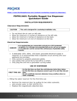
SPECIFICATIONS: Ice Machine
ELECTRICAL
INLET
3"
2.1"
5.7"
WATER INLET
3
8
" FLARE
DRAIN
¾" FPT
BACK VIEW: AIR COOLED
5.25"
9.5"
Note: Air cooled models
require space at the
sides and back for air
flow. All models require
space for service.
Model Number Dimensions
(w/o bin)
Basic Electrical Ice Type Condenser
Type
Minimum
Circuit
Ampacity
Maximum
Fuse Size
Refrigerant
Charge
R-404A*
WxDxH
FME1204AS-3B 21" x 24" x 27" 208-230/60/3 FLAKE Air 8.4 15 30 oz
FME1204WS-3A same same FLAKE Water 7.9 15 24 oz
FME1204WS-3B same same FLAKE Water 7.9 15 22 oz
FME1204AS-32B same 208-230/60/1 FLAKE Air 11.3 15 30 oz
FME1204WS-32A same same FLAKE Water 10.8 15 24 oz
FME1204WS-32A same same FLAKE Water 10.8 15 22 oz
NME954AS-3B same 208-230/60/3 NUGGET Air 8.4 15 30 oz
NME954WS-3A same same NUGGET Water 7.9 15 24 oz
NME954WS-3B same same NUGGET Water 7.9 15 22 oz
NME954AS-32B same 208-230/60/1 NUGGET Air 11.3 15 30 oz
NME954WS-32A same same NUGGET Water 10.8 15 24 oz
NME954WS-32B same same NUGGET Water 10.8 15 22 oz
* Refrigerant charge change on water cooled. Always check the nameplate for charge data.

NME954 & FME1204
June 2006
Page 3
SAMPLE BIN AND MACHINE COMBINATIONS
FME1204 ON BH550*
NME954 ON BH800
or BH801*
FME1204 ON BH900*
* Bin Top Kit Required
The Nameplate is
located on the back
of the machine.

FOR THE INSTALLER
Notice:
Scotsman Ice Systems are designed and
manufactured with the highest regard for safety
and performance. They meet or exceed the
standards of UL, NSF and CUL.
Scotsman assumes no liability or responsibility of
any kind for products manufactured by Scotsman
that have been altered in any way, including the
use of any part and/or other components not
specifically approved by Scotsman.
Scotsman reserves the right to make design
changes and/or improvements at any time.
Specifications and design are subject to change
without notice.
Location:
Installation Limitations:
This ice system is designed to be installed indoors,
in a controlled environment:
Min Max
Air Temperature 50
0
F 100
0
F
Water Temperature 40
0
F 100
0
F
Water Pressure 20 PSI 80 PSI
Voltage 198 253
(Compared to the nameplate)
Operating the machine outside of the limitations is
misuse and can void the warranty.
RO Water Limitation: Water conductivity must be
no less than 35 microSiemens/cm.
Only install the machine in a location where there
is enough space around it so that it is accessible
for service.
Keep the back of air cooled machines a minimum
distance of 6" from a wall for air circulation. Try to
avoid hot, dirty and crowded locations. Be sure
that the location for the machine is within the
environmental limitations.
Storage Bin:
Tip the storage bin on its back, using parts of the
carton to protect the exterior finish. Remove the
skid and install the legs into the threaded holes in
the bottom of the bin. Turn the leg levelers all the
way in preparation for leveling later. Return the bin
to the upright position, remove paper covering the
bin gasket.
Note: Do not push bin into position, instead lift it
there. Pushing a bin, especially one with ice in it,
can cause damage to the legs and the leg mounts.
Install the appropriate bin top on the bin, according
to the instructions for the bin top.
Ice Machine:
The machine is heavy, so the use of a mechanical
lift is recommended for lifting the machine high
enough to install on top of the bin. After the unit is
placed on the bin, line it up so it is even with the
back side. Secure the machine to the bin with the
hardware provided with the machine.
Remove the front panel and remove any shipping
blocks.
NME954 & FME1204
June 2006
Page 4

NME954 & FME1204
June 2006
Page 5
FOR THE INSTALLER: Location
A proper installation locates the machine indoors,
but in a place where the heat and noise it
produces are not objectionable.
Air cooled machines discharge hot air out the
back. A minimum of 6" of space must be allowed
at the back and sides for adequate operation of an
air cooled unit.
Space for maintenance access is also important. If
two units are placed side by side on a bin, side
access becomes even more important.
A 6" space above the machine is needed to
remove the auger.
Airflow Change:
Air flow through air cooled models changed in
2006 from in the front and out the back to in the
sides and and out the back. Units with
non-louvered panels flow in the sides and out the
back.

FOR THE PLUMBER
CONFORM TO ALL APPLICABLE CODES
Water Inlet
Air Cooled Models: The recommended water
supply is clean, cold water. Use
3
8
" O.D. copper
tubing, connect to the
3
8
" male flare at the back of
the cabinet. Install a hand valve near the machine
to control the water supply.
Water Treatment: In most areas, a water filter of
some type will be useful. In areas where the water
is highly concentrated with minerals the water
should be tested by a water treatment specialist,
and the recommendations of the specialist
regarding filtration and/or treatment should be
followed.
Water Cooled Models: A separate
3
8
" O.D. copper
line is recommended, with a separate hand valve
to control it. Connect it to the
3
8
" FPT condenser
inlet at the back of the cabinet. The water pressure
to all lines must always be above 20 psig, and
below 80 psig.
Drains
Air Cooled Models: Connect a rigid drain tube to
the
3
4
" FPT drain fitting at the back of the cabinet.
The drain is a gravity type, and ¼ inch per foot fall
is the minimum acceptable pitch for the drain
tubing. There should be a vent at the highest point
of the drain line, and the ideal drain receptacle
would be a trapped and vented floor drain. Use
only
3
4
" rigid tubing.
Water Cooled Models: Connect a separate drain
line to the
1
2
" condenser drain connection at the
back of the cabinet. Do not vent this drain.
Storage Bin: Connect a separate gravity type
drain to the ice storage bin drain. Vent this drain if
there is a long horizontal run from the bin to the
floor drain. Insulation of this drain line is
recommended.
NME954 & FME1204
May 2001
Page 6
WATER
COOLED
Hand
Valve
Condenser
Inlet
Water Filter
Condenser
Drain
Vented
Drain
AIR COOLED
MODELS
Hand
Valve
Field
Supplied
Filter
Water
Inlet
Vented
Floor

FOR THE ELECTRICIAN
CONFORM TO ALL APPLICABLE CODES
Check the nameplate (located on the back panel)
for the voltage requirements, and for the minimum
circuit ampacity. The machine requires a solid
chassis to earth ground wire.
Connect the power supply to the wires leads in the
junction box on the back of the machine.
Connect the ice machine to its own electrical circuit
so it is individually fused. Voltage variation must
remain within the limitations, even under starting
conditions.
All external wiring must conform to national,
state, and local electrical codes. The use of a
licensed electrician is required to perform the
electrical installation.
NME954 & FME1204
May 2001
Page 7
WATER COOLED
AIR COOLED
POWER
SUPPLY

FOR THE INSTALLER
Final Check List
____1. Is the ice system installed indoors in a
location where the air and water
temperatures are controlled, and where
they do not exceed the design limitations?
____2. Is there an electrical service disconnect
within sight of the installed machine? Has
the voltage been checked, and compared
to nameplate requirements?
____3. Have all the plumbing connections been
made and checked for leaks?
____4. Has the machine and bin been leveled?
____5. Is there a minimum of 6" clearance at the
back of the machine for proper service
access and air circulation?
____6. Is the water pressure a minimum of 20
psig?
____7. Has the machine been secured to the bin?
____8. Is there clearance over the top of the
machine for service access?
____9. Is there a water shut off valve installed near
the machine?
____10. Have all of the shipping blocks been
removed?
NME954 & FME1204
May 2001
Page 8

START UP
Pre-Start Inspection
1. Remove the front and side service panels.
2. Check that any shipping blocks have been
removed.
3. Inspect the interior of the machine for loose
screws or wires. Check that no refrigerant lines
are rubbing each other. Check that the fan blades
turn freely (air cooled).
4. Check that the unit is installed correctly
according to the final check list (page 8).
Start Up
1. Go through the prestart inspection.
2. Open the hand valve, observe that water enters
the water reservoir, fills the tube from the reservoir
to the evaporator, and then shuts off. Check for
leaks.
3. Switch the master (mode) switch on.
The electrical start up sequence is automatic.
A. There should be a short (15 second) delay
before the gear motor starts.
B. After the gear motor starts, the compressor will
start.
4. On air cooled models, the condenser will begin
to discharge warm air, on water cooled models, the
water regulating valve will open, and warm water
will be discharged into the drain.
5. The unit should soon be making ice, if desired,
the low side pressure may be checked: it should be
32 psig + or - 2 psig.
The suction line temperature at the compressor is
normally very cold, nearly to the point of frost up to
the compressor body, but not on it.
The air cooled discharge pressure will depend
upon air and water temperatures, but should be
between 200 psig and 280 psig.
The water cooled discharge pressure should be
constant at about 245 psig.
The above numbers are for new, clean machines,
you can expect to see some values higher, and
some lower between different units.
6. THERE ARE NO ADJUSTMENTS TO MAKE,
so replace the panels.
7. Clean and/or sanitize the storage bin interior,
wipe off the exterior with a clean, damp cloth.
8. Give the owner/user the service manual, instruct
him/her in the operation of the unit, and make sure
they know who to call for service.
9. Fill out the manufacturer's registration and mail it
to Scotsman.
NME954 & FME1204
May 2001
Page 9

COMPONENT DESCRIPTION
Control Box: Contains the electrical controls that
operate the machine.
High Pressure Cut Out Switch: An auto-reset
switch sensing the high side refrigeration pressure.
It will shut the machine off if the discharge
pressure should ever exceed 450 psig.
Low Pressure Cut Out Switch: An auto-reset
switch sending the low side of the refrigeration
system. It will disconnect power to the circuit board
and shut down the machine if the low side
pressure falls too low.
Evaporator: A vertical stainless steel tube,
refrigerated and water filled. In it there is a
stainless steel auger.
Compressor: The refrigerant vapor pump.
Reservoir: Float operated, it maintains the water
level in the evaporator at a constant level, it also
contains the water level sensor.
Water Level Sensor: Senses if there is water in
the reservoir to make ice
out of. Will shut the
machine off it there is
none.
Ice Discharge Chute:
Directs the ice produced
by the evaporator into the
storage bin.
Ice Level Sensor: An
electronic “eye”, it senses
the presence of ice in the
bottom of the ice
discharge chute.
Operates to turn the ice
machine on and off
automatically as the level
of ice in the bin changes.
Gear Motor: An oil filled,
speed reduction gearbox,
driving the auger.
Drain Tube: When
uncapped and lowered,
drains the evaporator.
Condenser: Air or water
cooled, where the heat
removed in ice making is
discharged.
Expansion valve: The
refrigerant metering
device.
NME954 & FME1204
May 2001
Page 10
AIR COOLED
CONTROL BOX
Condenser
Expansion
Valve
Reservoir
Ice Chute
Compressor
Ice Level
Sensors
Drain
Tube
Hi Pressure
Cut Out
Low
Pressure
Cut Out

COMPONENT DESCRIPTION
Evaporator: A refrigerated vertical tube filled with
water and containing a water seal and auger.
Auger: A solid stainless steel double spiral auger,
it pushes the ice crystals up to the top of the
evaporator.
Water Seal: A two part “face” seal, the top half
rotating with the auger, the bottom half stationary,
the sealing action being where the two seal “faces”
meet.
Ice Sweep: A plastic cap with “fingers”. It revolves
with the auger to “sweep” the ice into the ice chute.
Breaker (Divider): Where the ice is compressed
and much of the extra water is squeezed out of it
before it is discharged into the bin.
Motor: A split phase motor that drives the gear
reducer.
Thrust Bearing: As the ice is pushed up the
evaporator, the auger is thrust down, and pressure
from the auger thrust is taken up by this bearing.
NME954 & FME1204
May 2001
Page 11
Water
Seal
Ice Sweep
Bearing
Breaker/Divider
Auger
Evaporator
Motor

CONTROL BOX: Components
Contactor: A definite purpose contactor
connecting the compressor and the fan motor to
the power supply.
Circuit Board: Controls the operation of the ice
machine using input from sensors and pressure
controls. Switches loads on and off thru relays.
See photo below.
Potential Relay: The compressor start relay.
Mode (On/Off) Switch: Manual control for the
machine.
NME954 & FME1204
May 2001
Page 12
Power Light
Service Light
Water OK Light
Bin Full
Light
Freeze Light
Compressor
Relay
Auger
Relay
Control Board
LED1
LED3

ELECTRICAL SEQUENCE:
There are 7 indicator lights on the control board:
·
WTR-OK (Water OK). Green. Normal =
Glowing. Glows when there is water in the
reservoir.
·
PWR-OK (Power OK). Green. Normal =
Glowing. Glows when the control board has
power and is functional.
·
Service. Red. Normally Off.
·
Freeze. Red. Normally glowing when making
ice.
·
Bin Full. Red. Normally Off when making ice.
·
LED1. White. Located next to the board’s
Compressor Relay. Normally Glowing when
making ice.
·
LED3. White. Located next to the board’s Auger
Motor Relay. Normally Glowing when making
ice.
If the machine is switched off at the mode switch,
but is otherwise ready to go, switching the mode
switch to ON does the following:
·
The PWR-OK light glows.
·
If there is water in the reservoir the WTR-OK
light glows.
·
After 10 seconds the Freeze, LED1 and LED3
lights glow and the machine starts up.
Start Up:
·
The compressor relay and auger motor relay
become energized, connecting power to the
windings of the auger motor and contactor coil.
·
The contactor is energized, connecting power to
the compressor, and the compressor starts.
·
As ice is made it passes between the ice level
sensors but because it is not a continuous
stream it only interrupts the sensor’s infrared
beam momentarily. The bin full light remains off
and the machine stays on until ice builds up in
the bin and blocks the path between the
sensors for 6 seconds or longer. When that
occurs the bin full light glows and the machine
shuts down.
Shut Down:
·
The compressor relay opens, LED1 goes out.
·
The compressor contactor opens
·
The compressor stops
·
The auger motor stays on for 1 more minute,
clearing out ice in the evaporator, and then
·
The auger motor relay opens, LED3 goes out
and the auger motor stops.
The compressor will not restart until 2 minutes or
more have passed after the last shut down.
If the path between the ice level sensors remains
clear for more than 10 seconds the ice machine
will restart.
Control Board Protection Devices
·
When the water level in the reservoir falls
below the water level sensor’s tip, the WTR-OK
light goes out and the machine shuts down.
When water refills the reservoir the WTR-OK
light glows and the machine starts up again.
·
If the auger drive motor current becomes
excessive the compressor and auger drive
motor will be switched Off and the Service light
will blink. The control board will restart the auger
drive motor in 4 minutes. If during the first 60
seconds after restart the auger motor current
stays within limits, the compressor is restarted
and the machine returns to normal operation. If
the auger motor’s current is excessive within 60
seconds after the restart, the process will be
repeated once more. If during that try the
current is still excessive the machine shuts
down and must be manually reset. The service
light will then be glowing continuously.
To Reset: Switch power to the unit off and then
on.
Other Protection Devices:
·
If the high pressure cut out switch opens the
machine will stop immediately. It will
automatically reset when the high pressure falls
below its cut in point.
·
If the low pressure cut out switch opens the
machine will stop immediately. It will
automatically reset when the pressure rises
above its cut in point.
·
The mode (on - off) switch is the manual
control for the complete machine, but it is not a
service disconnect.
NME954 & FME1204
May 2001
Page 13

OPERATION: Water
Water enters the machine through the 3/8" male
flare at the rear of the cabinet, goes to the water
reservoir which it enters through the float valve.
The water then goes out the bottom of the
reservoir tank to the bottom of the evaporator.
Reservoir overflow or evaporator condensation is
routed to the drain. Water cooled models have a
separate water circuit for the cooling water: it
enters the fitting at the rear, goes to the water
regulating valve, then to the water cooled
condenser and down the drain.
NME954 & FME1204
May 2001
Page 14
Evaporator
Drain
Water Level
Evaporator
Ice
Chute
Drain
WATER SCHEMATIC
Reservoir
Water Inlet
Evaporator Inlet

NME954 & FME1204
May 2001
Page 15
OPERATION: Performance
Typical Low Side Pressure
·
Air Cooled: 34 - 38 PSIG
·
Water Cooled: 32 PSIG
Typical Discharge Pressure
·
Air Cooled: 220 - 275 PSIG
·
Water Cooled: 245 PSIG
Typical Compressor Amp Draw
·
Single phase = 4.3
·
Three phase = 2.8
Superheat
·
5 - 7 degrees
High Pressure Cut Out (auto reset)
·
450 PSIG
Low Pressure Cut Out (auto reset)
·
15 PSIG
Refrigerant Charge
· Air Cooled: 30 ounces R-404A
·
Water Cooled: 24 ounces R-404A
Condenser
Fan
Motor
Liquid
Line
Thermostatic
Expansion Valve
Suction Line
Gear
Motor
Compressor
Discharge
Line
Refrigeration Schematic
Evaporator

SANITIZING AND CLEANING
It is the USER’S RESPONSIBILITY to keep the ice machine and ice storage bin in a sanitary condition.
Without human intervention, sanitation will not be maintained. Ice machines also require occasional
cleaning of their water systems with a specifically designed chemical. That chemical dissolves mineral
build up that forms during the ice making process.
Sanitize the ice storage bin as frequently as local health cods require, and every time the ice machine is
cleaned and sanitized.
Maintenance and Cleaning should be scheduled at
a minimum of twice per year.
ICE MAKING SYSTEM: In place cleaning
1. Check and clean any water treatment devices, if
any are installed.
2. Remove screws, and the front and top panels.
3. Move the ON-OFF switch to OFF.
4. Remove all the ice from the storage bin.
5. Remove the cover to the water reservoir and
block the float up.
6. Drain the water reservoir and freezer assembly
using the drain tube attached to the freezer water
inlet. Return the drain tube to its normal upright
position and replace the end cap.
7. Prepare the cleaning solution: Mix eight ounces
of Scotsman Ice Machine Cleaner with three quarts
of hot water. The water should be between 90-115
degrees F.
8. Slowly pour the cleaning solution into the water
reservoir until it is full. Wait 15 minutes, then
switch the master switch to ON.
9. As the Ice Machine begins to use water from
the reservoir, continue to add more cleaning
solution to maintain a full reservoir.
10. After all of the cleaning solution has been
added to the reservoir, and the reservoir is nearly
empty, switch the master switch to OFF.
11. After draining the reservoir, as in step 6, wash
and rinse the water reservoir.
12. Go thru steps 13-18 to sanitize the ice machine
water system.
13. Mix two gallons of sanitizer solution. Use an
approved sanitizer.
A possible sanitizer solution may be obtained by
mixing two gallons of warm (90-115
o
F.) potable
water with 1 ounce of household bleach.
14. Slowly pour the sanitizer solution into the water
reservoir until the float rises, then switch the
master switch ON.
15. As the ice machine uses water from the
reservoir, continue to pour the sanitizer solution
into the reservoir.
16. After
1
2
of the sanitizer solution has been added
to the reservoir, and the reservoir is nearly empty,
switch the master switch OFF.
17. Drain the reservoir and thoroughly wash the
interior of the reservoir and cover with sanitizer
solution.
18. Remove the block from the float in the water
reservoir.
19. Switch the master switch to ON
20. Continue ice making for at least 15 minutes, to
flush out any cleaning solution. Switch the master
switch OFF.
DO NOT USE any ice produced from the
cleaning solution.
Be sure no ice remains in the bin.
21. Remove all ice from the storage bin.
22. Add warm water to the ice storage bin and
thoroughly wash and rinse all surfaces within the
bin.
23. Sanitize the bin interior by thoroughly washing
the interior of the bin and bin door with the balance
of the sanitizer solution.
24. Switch the master switch ON.
25. Replace the panels.
NME954 & FME1204
May 2001
Page 16
Scotsman Ice Machine
Cleaner contains acids.
These compounds may
cause burns.
If swallowed, DO NOT
induce vomiting. Give large
amounts of water or milk.
Call Physician immediately.
In case of external contact,
flush with water.
Keep out of the reach of
children.

1. The bin control uses devices that sense light,
therefore they must be kept clean enough so that
they can “see”. At least twice a year, remove the
bin control sensors from the base of the ice chute,
and wipe the inside clean, as illustrated.
2. The ice machine uses a probe in the reservoir to
determine if there is water.
At least twice a year remove the
probe from the reservoir and wipe
the tip clean of mineral build-up.
NME954 & FME1204
May 2001
Page 17
Ice Level Sensors:
Slide To Remove
Clean The Ice
Level Sensors
SENSOR MAINTENANCE
Clean the Probe's Tip with ice
machine cleaner and a clean,
soft cloth.

BEARING MAINTENANCE
The bearing in the breaker should also be checked
at least two times per year.
Switch the machine Off and check the bearing:
·
removing the ice chute cover
·
unscrewing the ice sweep
·
removing the water shed & unscrewing the
breaker cover (left hand threads).
·
unscrewing the auger stud
Inspect the bearing. There should be plenty of
grease in sight. If grease is needed the bearing
and breaker should be removed to check the
action of the bearing. It should rotate smoothly.
To remove the breaker remove the lower ice chute
then take out all four allen head cap screws and
pull the breaker off the auger and evaporator.
If the bearing only needs grease, inject grease into
the bearing using Scotsman grease needle pn
02-3559-01 and Scotsman bearing grease
cartridge, pn A36808-001. Be sure to inject grease
evenly and thoroughly.
See Removal and Replacement section to replace
bearing or seals.
Reverse to reassemble.
NME954 & FME1204
May 2001
Page 18
Chute Cover
Ice Sweep
O
f
f
Auger Stud
Cap Screw
Breaker
Cover
Needle, pn
02-3559-01
Bearing

NME954 & FME1204
May 2001
Page 19
Clean or replace the air filter.
Clean the air cooled condenser.
Air flow on this model is from front to back, so the
inside of the machine will have to be available to
clean the air cooled condenser. Use a vacuum
cleaner or coil cleaner if needed. Do NOT use a
wire brush.
A. Disconnect electrical power, and remove the
filter. The filter may be cleaned or replaced.
B. Clean the condenser: the condenser may
appear to be clean on the surface, but it can still be
clogged internally. Check with a flash light from the
front to see if light can be seen though the
condenser fins. Reverse to reassemble.
MAINTENANCE: Air Cooled
REMOVE TWO SCREWS & UNPLUG FAN MOTORS.
PULL FAN MOTOR ASSEMBLY UP AND
TO THE RIGHT TO REMOVE
Electrical shock hazard.
Electrical shock can cause
personal injury.
Disconnect power before
beginning to service
components.

In some areas, the water supply to the Ice Machine
will contain a high concentration of minerals, and
that will result in an evaporator and auger
becoming coated with these minerals, requiring a
more frequent removal than twice per year. If in
doubt about the condition of the evaporator and
auger, the auger can be removed so the parts can
be inspected.
Note: Water filters can filter out suspended solids,
but not dissolved solids. “Soft” water may not be
the complete answer. Check with a water
treatment specialist regarding water treatment.
For more information on removal of these
parts, see REMOVAL AND REPLACEMENT.
Turn off the water supply.
1. To remove the auger, remove the front and top
panels.
2. Push back bail clamp holding ice chute cover to
ice chute, and remove cover.
3. Unscrew and remove ice sweep.
4. Remove ice chute from evaporator.
5. Remove 4 allen screws holding breaker to
evaporator.
6. Drain the evaporator by lowering and uncapping
the evaporator drain hose.
7. Pull up to remove auger.
After the auger has been removed, allow the auger
to dry: if the auger is not bright and shiny, it must
be cleaned.
Clean the auger and evaporator as required. DO
NOT HONE THE EVAPORATOR.
8. Replace the water seal.
9. Reverse to reassemble.
NME954 & FME1204
May 2001
Page 20
AUGER MAINTENANCE
ALLEN
SCREWS
BREAKER &
BEARING &
AUGER
ASSEMBLY
The auger has sharp
edges, handle with care.
Moving parts hazard.
Moving parts can cause
personal injury.
Disconnect power before
beginning to service
components.
Page is loading ...
Page is loading ...
Page is loading ...
Page is loading ...
Page is loading ...
Page is loading ...
Page is loading ...
Page is loading ...
Page is loading ...
Page is loading ...
Page is loading ...
Page is loading ...
/