Page is loading ...

DIGITAL VIDEO RECORDER
SHR-3010
User’s Manual
CLASS A (For Business)
To use this product safely, have to read “Important Safety Introductions”, and then
be well aware of the contents.
GB
D
F
ES
I

GB
iii
GB
ii
DIGITAL VIDEO RECORDER
Important Safety Instructions
1. Read these instructions.
2. Keep these instructions.
3. Heed all warnings.
4. Follow all instructions.
5. Do not use this apparatus near water.
6. Clean only with dry cloth.
7. Do not block any ventilation openings. Install in accordance with the
manufacturer’s instructions.
8. Do not install near any heat sources such as radiators, heat registers, or other
apparatus (including amplifiers) that produce heat.
9. Do not defeat the safety purpose of the polarized or grounding-type plus.
A polarized plug has two blades with one wider than the other. A grounding type
plug has two blades and a third grounding prong. The wide blade or the third prong
are provided for your safety. If the provided plug does not fit into your outlet,
consult an electrician for replacement of the obsolete outlet.
10.Protect the power cord from being walked on or pinched particularly at plugs,
convenience receptacles, and the point where they exit from the apparatus.
11. Only use attachments/accessories specified by the manufacturer.
12.Use only with cart, stand, tripod, bracket, or table specified by
the manufacturer, or sold with the apparatus. When a used,
caution when moving the cart/apparatus combination to avoid
injury from tip-over.
13.Unplug this apparatus. When a cart is used, use caution when
moving the cart/apparatus combination to avoid injury from tip-over.
14.Refer all servicing to qualified service personnel. Servicing is required when the
apparatus has been damaged in any way, such as power-supply cord or plug is
damaged, liquid has been spilled or objects have fallen into the apparatus, the
apparatus has been exposed to rain or moisture, does not operate normally, or has
been dropped.
To prevent damage which may result in fire or electric shock hazard, do not expose
this appliance to rain or moisture.
This device complies with part 15 of the FCC Rules. Operation is subject to the
following two conditions.
1) This device may not cause harmful interference, and
2) This device must accept any interference that may cause undesired operation.
CAUTION
Danger of explosion if battery is incorrectly replaced.
Replace only with the same or equivalent type recommended by the manufacturer.
Dispose of used batteries according to the manufacturer’s instructions.
CAUTION
RISK OF ELECTRIC
SHOCK DO NOT OPEN
CAUTION : TO REDUCE THE RISK OF ELECTRIC SHOCK, DO
NOT REMOVE COVER (OR BACK). NO USER
SERVICEABLE PARTS INSIDE. REFER SERVICING
TO QUALIFIED SERVICE PERSONNEL.
This symbol indicates high voltage is
present inside. It is dangerous to make
any kind of contact with any inside part
of this product.
This symbol alerts you that important
literature concerning operation and
maintenance has been included with
this product.

Contents
iii
v
1
2
3
1-1
1-2
1-3
1-7
1-8
2-1
2-2
2-3
2-4
3-1
3-4
3-9
3-14
3-15
3-18
3-22
3-23
3-24
3-25
3-26
iv
iv v
Important Safety Instructions
Contents
I. Summary
1. Introduction
2. Characteristics
3. Name and Function of Each Part
4. Unpacking
5. HDD Addition
II. Connection with Other Devices
1. Connection to External Devices
2. Connection with Multiplexer
3.
System Connection for Alarm Recording
4. Connection with PC for Use
III. Basic Method to Use
1. Booting the System
2. Basic Screen Viewing
3. Menu View
4. Setting of Date, Time and Screen
5. Record Setup
6. Alarm Record Setup
7. Reservation Record Setup
8. System Setup
9. Communication Setup
10. System Information
11. Backup Setting
(SCSI HDD BACKUP)
IV. Record
1. Basic Record
2. Record Lock
3. Alarm Record
4. Reservation Record
V. Retrieval and Playback
1. Retrieval Menu View
2. Retrieval by Data and Time
3.
Recorded Data List View
4. Alarm Record Retrieval
5. Power On/Off Status List View
6. Basic Playback
7. Various Screen View Using
JOG/SHUTTLE
VI. Others
1. Product Standards
2. Appearance Drawing
VII. Appendices
1. Chech Points before Call Service
2. Q&A
4
4-1
4-3
4-4
4-5
5
5-1
5-3
5-4
5-5
5-6
5-7
5-9
6
6-1
6-2
7
7-1
7-3
~
GB GB

1
I. Summary
GB

1-2
GB
1-1
DIGITAL VIDEO RECORDER
1
Introduction
2
Characteristics
The Digital Video Recorder SHR-3010 is a Digital Time Lapse Recorder to utilize its
HDD as a recording media. How to use it is simple and therefore existing users of
Time Lapse VCR can also access to it since it is built with Jog/Shuttle. You can also
perform continuous recording on the HDD and directly view image recorded without
turning videotapes as in the existing Time Lapse VCR. SHR-3010 can record both
image and sound simultaneously, directly control the system from an external PC, and
back up data with an external SCSI HDD.
■ Upon booting the system, it recognizes automatically whether the incoming
signal is NTSC or PAL signal.
■ Adjusting screen quality in 4-steps
● Very High, High, Normal, Low
■ Variously changing numbers of recording fields per second.
● NTSC: 60 ~ 0.50 Fields/sec
● PAL: 50 ~ 0.50 Fields/sec
■ Simultaneous recording and regeneration
■ Reservation recording by using timers
■ Recording by alarm
■ Motion detection function and alarm occurrence or recording available in
motion detection
■ Multiplexer link
■ Various regeneration speed
● Frame Advance by Jog
● 1/5, 1/2, 1, 2, 5, 10, 20 baud rate (forward, backward)
■ Convenient retrieval function
● Date & Time Search, Alarm Event Search, Record Event Search
■ Convenient operation by using Jog/Shttle
■ Remote monitoring and control via LAN
● Network Interface: Ethernet (10/100BaseT)
● Protocol: TCP/IP
● Web Server: Image capture and remote monitoring through a Viewer Program installed at
PC
■ Automatic booting of system in power failure recovery during recording mode,
and starting of recording
■ Remote control by series communication
● RS232 1 port
● RS485 2 ports (connection of up to 32 sets)
●
Camera PAN/TILT/ZOOM Control of LAN VIEWER PROGRAM via Controlling RS-485
■ The recorded state and remnant hard disk space are displayed as bars on the
screen and especially in the play mode, the part currently being played of the
total hard disk capacity is displayed in the bar.
■ You can record video and audio at the same time.
■ Besides English, multi-language support provides German, French, Spanish,
and Italian.
■ You can back up data with SCSI.
■ You can control the camera and select channels with the Remote Viewer
Program. (For SAMSUNG model only :SCC-641, 643 Camera, SCC-421 Series
(C4201, C4203,C 4301, C4303) Camera, SDM-160 Multiplexer)
GB

No Name Function
DOWN ( )
SET/STILL
( )
RIGHT ( )
PLAY ( )
RECORD ( ● )
REC LOCK( )
STOP ( ■ )
JOG/SHUTTLE
( / )
Used when moving cursor to the lower item of menu or
reducing values in setting-up details of menu.
Used when temporarily stopping during play or desiring to see
still screen. Plays a role as Enter in menu setup.
Used when fast forwarding during play of recorded image or
desiring to see still screens sequentially, or changing or editing
the left settings in setting-up details of menu.
Plays recorded data.
Records current live image.
Prevents other keys from being entered during record.
Stops play or record.
Used when moving cursor in menu setup or changing values
in setting-up details of menu. In addition, used when viewing
frames one by one during temporary stop in data play mode or
changing play speed.
1-3 1-4
DIGITAL VIDEO RECORDER
3
Name and Function of Each Part
GBGB
Front View
1 2 93 7 8 10 11 13124 5 6
No Name Function
STATUS
DISPLAY LED
Displays system status.
●
POWER : Checks power On.
●
HDD : Checks normal access to HDD.
●
FULL : Check if the hard disk is full.
●
ALARM : Check Alarm turns operates.
●
LAN : Checks LAN normally operates.
●
LOCK : Checks Recording Lock function
operates.
Used when displaying menu for setting-up systems or
entering from the sub menu to the top menu.
Displays recorded data lists. You can play it if selecting
each of them, pressing SET/STILL( ) button and
then pressing the PLAY( ) button.
Used when desiring to rewind during play of recorded image
or see still screen in reverse, or changing or editing the left
settings in setting-up details of menu.
Used for rewinding during play of recorded image or see
still screen in reverse or changing or editing the left
settings in setting-up details of menu.
SEARCH
MENU
LEFT ( )
UP ( )
1
2
3
4
5
6
7
8
9
10
11
12
13

GB
1-6
GB
1-5
DIGITAL VIDEO RECORDER
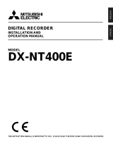
Rear View
1
2
3
4
5
No Name Function
EXTERNAL I/O
PORT
FAN
AC IN
POWER
●
ALARM IN: In the N.C. (Normally Closed) mode, the system
recognizes an alarm when a High (5V) signal is input for over
0.5 seconds. In the N.O. (Normally Open) mode, the system
recognizes an alarm when a Low (0V) signal is input for over
0.5 seconds. (Please refer to “➁ALARM DETECT TYPE”
on p. 3-18.)
●
ALARM RESET: The alarm mode is cleared when a Low (0V)
signal is input for over 0.5 seconds.
●
ALARM OUT: A High (5V) signal is output during alarm
recording.
●
TRIGGER OUT: This signal is for switching the recording
output screen of the Multiplexer.
●
REC IN: The system begins recording when a Low (0V) signal
is input for over 0.5 seconds.
●
DISK END: If the DISK END MODE of the RECORD
MODE SETUP is set to STOP, a Low (0V) signal is output for
about 1 second when the HDD becomes full during recording.
(Please refer to “➃DISK END MODE” on p. 3-16.)
Fan
Connects power cable.
Power On/Off button.
8
9
10
11
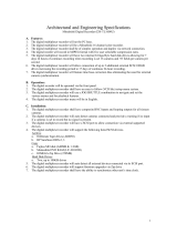
1 2 3 4 7 95 108 116
No Name Function
RS232 PORT
RS485 PORT
VIDEO IN/OUT
AUDIO IN/OUT
LAN
MODE
SCSI
Serial Port for remote control.
Serial Port for remote control.
Composite image signal I/O terminal (BNC Style Connector).
Audio Signal Input/Output Jacks (RCA Jacks).
LAN Cable Connection Terminal.
It is the DIP switch to set System ID, Direct Communication,
Termination, etc.
●
1~5 : System ID.
(Depending on you turn the switch on and
off, it will be set to High(1) and Low(0) respectively.)
●
6 : Not Use.
●
7 : Termination On/Off (Of all the directly connected
systems, it sets the last system as On).
(Depending on you turn the switch on and off, it will
be set to Off and On respectively.
●
8 : Not Use.
SCSI Connector for Data Backup
6
7

Caution
Caution
The above contents can be changed without notice in order to improve the
performance or function of the product.
1-7
1-8
DIGITAL VIDEO RECORDER
4
Unpacking
GBGB
5
HDD Addition
When purchasing product, first remove packing and put it on a flat floor or at a place to use it.
Then, ensure all following contents are included:
◗ Main body
◗ User’s Manual
◗ 1 power cord
◗ 2 Rack Mount Adapter
◗ SCREW-MACHINE (PH, UNC6-32, L4.2, WHT) x 4
◗ Remote Viewer Program Installation CD
Mounting HDD
1. Unfasten the SCREW-SPECIAL (BWH, M4, L8, WHT) 11 EA attached to the left, right,
and rear of the product, and then remove the CABINET-TOP from the product.
2. Unfasten the SCREW-TAPTITE (BH, M3, L6 WHT) 3 EA to remove the HDD from the
BRACKET-HDD as shown in the picture.
3. Attach the HDD to the BRACKET-HDD as shown in the picture, and fasten the SCREW-
MACHINE (PH, UNC6-32 L4, WHT) 4 EA supplied as ACCESSORY.
4. Place the HDD with the BRACKET-HDD inside the product, and fasten the SCREW-
TAPTITE (BH, M3, L6 WHT) 3 EA.
5. Connect the Power Supply Cable and the AT-Bus Interface Cable. (Refer to “Cable
Connection” on page 1-10.)
6. Put the CABINET-TOP back on, and fasten the SCREW-SPECIAL (BWH, M4, L8,
WHT).
Caution
Caution
Basically, a product with two HDDs has two HDDs attached to the HDD brackets
as it is introduced to the market. And a product with a single HDD is supplied
with an extra HDD bracket aside from the HDD bracket for attaching the HDD.
HDD
BRACKET- HDD
SCREW-MACHINE(PH, UNC6-32, L4, 2, WHT)
SCREW-SPECIAL(BWH, M4, L8, WHT)
SCREW-TAPTITE(BH, M3, L6, WHT)
CABINET-TOP

GB
1-10
GB
1-9
DIGITAL VIDEO RECORDER
Mode setup and cable connection
Set a HDD mode and connect cables after mounting the HDD to product.
Below is shown drawing of Power Connector and AT-Bus Interface Connector and
Configuration Jumper Block of HDD.
Setting of HDD mode is performed in a Configuration Jumper Block.
When mounting two hard disk drives on the product, one should be set in the Master Mode
and the other in the Slave Mode. Basically, since the hard disk drive mounted on the product is
in the Master Mode, when mounting a new hard disk drive it can be set in the Slave Mode.
For example, mode is set as follows in case of Samsung Spinpoint V80 HDD:
AT-Bus Interface Cable and Power Supply Cable are connected to AT-Bus Interface
Connector are connected by referring to following drawing to ensure the HDD mounted on
product can properly operate.
If successfully mounting the HDD on the product and then booting the system, the system
recognizes that a new HDD is mounted and starts to operate after formatting the first HDD.
Caution
Caution
Use the HDD installed by default infrom the factory.
Use FUJITSU MAP3367NP, SEAGATE BARRACUDA ST32171W products only for
SCSI HDD for backup.
AT-Bus
Interface
Connector
AT-Bus
Interface
Cable
Power Supply
Cable
(4Pin)
DC Power
Connector
40Pin
Header
40Pin
Bevel
Caution
Caution
Please be sure to turn the system off before you replace or add the HDD. If not,
the HDD may poorly operate or the life may be reduced.

II. Connection with
Other Devices
2
GB

2-2
GB
2-1
1
Connection to External Devices
2
Connection with Multiplexer
(e.g. connection to SDM-160)
DIGITAL VIDEO RECORDER
CAMERA RX SIREN LIGHT
VIDEO OUT
(NTSC/PAL MONITOR)
LAN
AUDIO OUT
SHR-3010 VIDEO RECORDER
■ This unit can be connected to external devices such as a camera for video signal input, a
microphone for audio signal input, and an NTSC or PAL monitor for video and audio signal
output.
■ It can be connected to external devices such as an alarm according to the user’s request.
■ It can be connected to a PC through a LAN or Serial connection for remote control.
■ Your may back up data with a backup device using SCSI for the purpose of data backup.
Caution
Caution
– A CRT monitor capable of displaying an NTSC or PAL video signal must be used
with this unit. An ordinary computer monitor cannot be used.
– The backup device of this equipment is applicable only to SCSI HDDs.
AC IN
CAMERA
1
2
3
.
.
.
16
MONITOR
OUT
TRIGGER OUT
ALARM IN
GND
SHR-3010 VIDEO RECORDER
SDM-160 DIGITAL MULTIPLEXER
VIDEO IN
VIDEO OUT
■ SDM-160 is a Multiplexer for NTSC, and SDM-160P is a Multiplexer for PAL.
■ For details on the functions of SDM-160, please refer to the user’s guide of SDM-160.
■ Connect this unit’s video signal input jack to the video signal output jack of SDM-160 and
connect this unit’s video signal output jack to the video signal input jack of SDM-160.
■ Connect the alarm output jack (ALARM OUT) of SDM-160 to this unit’s alarm input jack
(ALARM IN), and connect the VTI jack of SDM-160 to this unit’s trigger output jack
(TRIGGER OUT).
■ Connect both GND terminals together.
Caution
Caution
- Be sure to connect the trigger output terminal (TRIGGER OUT) of this unit to the
Multiplexer. Otherwise, a normal recording cannot be made.
(For the connection method, please refer to the user’s guide for the Multiplexer
you want to use.)
- If the system’s recording field rate is set to 0.50 ~ 15 FPS (Fields Per Second) for
the input NTSC video signal and to 0.50 ~ 12.5 FPS for the input PAL video
signal, be sure to set the Multiplexer in such a way that the recording output
screen is switched by the Trigger Pulse. (For settings related to the recording
field rate, please refer to “
##
PICTURE RATE” on p. 3-15.)
- If the system’s recording filed rate is set to 30 FPS for the input NTSC video
signal and to 25 FPS for the input PAL video signal, a half of the input video
channels may not be recorded depending on the type of Multiplexer. In this case,
set the recording field rate to 60 FPS for NTSC and to 50 FPS for PAL.
GB
MICROPHONE

2-3 2-4
DIGITAL VIDEO RECORDER
3
System Connection for Alarm Recording
GBGB
4
Connection with PC for Use
<Rear Side Connection Terminal of SHR-3010>
<Outside Product>
ALARM IN
ALARM RESET
ALARM OUT
TRIGGER OUT
GND
■ Alarm recording is a function for recording the input video when an alarm signal is input
while a device with alarm output is connected to this unit.
■ Connect to the corresponding terminals, as the numbers may be different for external
devices.
■ For external devices, if the alarm input (ALARM INPUT) and alarm cancel (ALARM
CANCEL) are not available, you can leave them unconnected.
GND
TRIGGER IN
ALARM IN
ALARM CANCEL
ALARM OUT
1
1
2
3
6
1
1
2
3
4
5
2 3 4 5 6 7 8 9 10 11 1 2 3 4 5
Connection with RS-232C
A. Communication Method
● Data Code: ASCII Code
● Protocol: 8 bit Data, 1 Stop bit, None Parity
● Transmission speed: 4800, 9600, 19200, 38400 bps
B. RS-232C terminal (D-SUB 9 Pin) and Pin specifications
51
69
Pin No Pin Specifications
2 TXD (Transmitted Data)
3 RXD (Received Data)
5 SG (Signal Ground)
1, 4, 6~9 NO Connection

GB
2-6
GB
2-5
DIGITAL VIDEO RECORDER
Connection with RS-485
Remote control is allowed through connection with RS-485 (up to 1.2km).
A. Communication method
● Data transmission method: Start-Stop Synchronized Serial Interface
● Protocol: 8 bit Data, 1 Stop bit, None Parity
● Transmission speed: 4800, 9600, 19200, 38400 bpss
B. RS-485 terminal and Pin specifications
C. Data Format (Samsung Protocol)
9 Byte Fixed
( ) : Byte numbers
Start Code (A0H)
(1)
Data Byte Type Contents Remarks
Byte 1 Start Code 0xA0 Start of Data Packet
Byte 2 Sender Addr. Transmission Address Source Range (0x00 ~ 0xFF)
Byte 3 Target Addr. Reception Address Destination Range (0x00 ~ 0xFF)
Byte 4 Only Image Recorder Command 0x0A
Byte 5 Key Function Range (0x01 ~ 0xFF)
Byte 6 Command 0xFF 0xFF
Byte 7 0xFF 0xFF
Byte 8 0xFF 0xFF
Byte 9 Check Sum Lower byte of (0xFFFF - (values adding Byte 2 ~ Byte 8))
Start Addr.
(1)
Target Addr.
(1)
Command
(5)
Check Sum
(1)
D. Code value by key
Function Byte 1 Byte 2 Byte 3 Byte 4 Byte 5 Byte 6, 7, 8 Byte 9
Response
(Byte 5)
[SET COMMAND]
MENU 0xA0 Src.Addr Dest.Addr. 0x0A 0x01 0xFF Check Sum 0x01
SEARCH 0xA0 Src.Addr Dest.Addr. 0x0A 0x02 0xFF Check Sum 0x02
SET/STILL 0xA0 Src.Addr Dest.Addr. 0x0A 0x03 0xFF Check Sum 0x03
UP 0xA0 Src.Addr Dest.Addr. 0x0A 0x04 0xFF Check Sum 0x04
DOWN 0xA0 Src.Addr Dest.Addr. 0x0A 0x05 0xFF Check Sum 0x05
LEFT 0xA0 Src.Addr Dest.Addr. 0x0A 0x06 0xFF Check Sum 0x06
RIGHT 0xA0 Src.Addr Dest.Addr. 0x0A 0x07 0xFF Check Sum 0x07
PLAY 0xA0 Src.Addr Dest.Addr. 0x0A 0x08 0xFF Check Sum 0x08
STOP 0xA0 Src.Addr Dest.Addr. 0x0A 0x09 0xFF Check Sum 0x09
RECORD 0xA0 Src.Addr Dest.Addr. 0x0A 0x0A 0xFF Check Sum 0x0A
REC LOCK 0xA0 Src.Addr Dest.Addr. 0x0A 0x0B 0xFF Check Sum 0x0B
F.Shuttle 1 0xA0 Src.Addr Dest.Addr. 0x0A 0x0C 0xFF Check Sum 0x0C
F.Shuttle 2 0xA0 Src.Addr Dest.Addr. 0x0A 0x0D 0xFF Check Sum 0x0D
F.Shuttle 3 0xA0 Src.Addr Dest.Addr. 0x0A 0x0E 0xFF Check Sum 0x0E
F.Shuttle 4 0xA0 Src.Addr Dest.Addr. 0x0A 0x0F 0xFF Check Sum 0x0F
F.Shuttle 5 0xA0 Src.Addr Dest.Addr. 0x0A 0x10 0xFF Check Sum 0x10
F.Shuttle 6 0xA0 Src.Addr Dest.Addr. 0x0A 0x11 0xFF Check Sum 0x11
F.Shuttle 7 0xA0 Src.Addr Dest.Addr. 0x0A 0x12 0xFF Check Sum 0x12
F.Shuttle 8 0xA0 Src.Addr Dest.Addr. 0x0A 0x13 0xFF Check Sum 0x13
R.Shuttle 1 0xA0 Src.Addr Dest.Addr. 0x0A 0x14 0xFF Check Sum 0x14
R.Shuttle 2 0xA0 Src.Addr Dest.Addr. 0x0A 0x15 0xFF Check Sum 0x15
R.Shuttle 3 0xA0 Src.Addr Dest.Addr. 0x0A 0x16 0xFF Check Sum 0x16
R.Shuttle 4 0xA0 Src.Addr Dest.Addr. 0x0A 0x17 0xFF Check Sum 0x17
R.Shuttle 5 0xA0 Src.Addr Dest.Addr. 0x0A 0x18 0xFF Check Sum 0x18
R.Shuttle 6 0xA0 Src.Addr Dest.Addr. 0x0A 0x19 0xFF Check Sum 0x19
R.Shuttle 7 0xA0 Src.Addr Dest.Addr. 0x0A 0x1A 0xFF Check Sum 0x1A
R.Shuttle 8 0xA0 Src.Addr Dest.Addr. 0x0A 0x1B 0xFF Check Sum 0x1B
R.JOG 0xA0 Src.Addr Dest.Addr. 0x0A 0x1C 0xFF Check Sum 0x1C
F.JOG 0xA0 Src.Addr Dest.Addr. 0x0A 0x1D 0xFF Check Sum 0x1D
E. Others
● Above data format and transmission speed may be changed depending on future
development conditions.
● PC operates as Master, and Target Set as Slave in transmission/reception of data.
● No status other than Set Key Function should be received. Provided, however, that con
tents recorded in a set should be always received for alarm function
(Some delay can be happen due to communication speed).

III. Basic Method
to use
3
GB

3-2
GB
3-1
DIGITAL VIDEO RECORDER
1
Booting the System
Power On
There is a power switch on the upper right hand side behind the system. Pull the power
switch up to boot the system. Then, the LED on front of the system is turned on, a blue
screen with the following message will appear and the system is booted.
When you turn the system on, a blue screen appears and starts searching HDD. The message
in the screen tells any HDD exists in the main body. The main body can contain 2 HDDs,
one is installed properly but the other is not yet installed.
If the second HDD is installed, the message, ‘HDD DETECTED =>2 OK’ will be displayed.
When booting is finished, the following Live screen will appear.
Recognizing incoming video signal
SHR-3010 system can automatically recognize whether the video signal connected at the input port
is NTSC or PAL signal upon booting the system.
When you turn the system on, it will recognize if the image signal is NTSC or PAL automatically to
set itself to the signal.
If the system power is turned on without connecting video signals to the input port, the
system remembers the last signal and the system is configured accordingly. For example, if the past
video signal connected to the input port was an NTSC signal, the system is configured to fit NTSC
signals and for PAL, the same process is applied to fit PAL signals. However, if suddenly a type of
video signal that is different from the video signal currently connected to the input port is connected,
the screen will malfunction. In short, this is a case where PAL signal is connected to a system
configured to satisfy NTSC signals or the other way around. In these cases, system power should be
turned off, the new signal connected and then the system turned back on in order to be configured to
recognize the new signal.
If you power on the system without attaching the hard disk drive, you will get an error message
indicating that no hard disk drive was found.
GB
HDD DETECTED => 1 OK
HDD DETECTED => 2 NOT EXIST
LOAD BOOT INFO...
LOAD CONFIGURATION...
SCSI DETECTION...
2001-09-15 17:14:55
HDD DETECTED => 1 NOT EXIST
HDD DETECTED => 2 NOT EXIST
1
Caution
Caution
Searching the installed SCSI HDD is allowed in the booting process only. In short,
the system is not able to recognize the SCSI while the system remains on though you
install the SCSI cable to the set. Please be sure to turn off the system before you
install the SCSI HDD.

3-4
GB
3-3
DIGITAL VIDEO RECORDER
GB
Power Off
Push the power switch down in order to turn off the system.
When the system power is turned off during recording, recording will be resumed next time
the system power is turned on and booting is complete.
Caution
Caution
Wait at least 3 seconds after turning off the system power before turning it back on.
Otherwise, the system may malfunction.
And the system will automatically keep on searching for a hard disk drive as shown below.
If you attach a hard disk drive at this time, the system will recognize the hard disk drive, the
boot process will end, and a live screen will appear.
2
Basic Screen Viewing
If system is in the recording state icon will blink. However, it does not blink in the
Live Screen state.
If the system is in the recording state due to alarm, icon appears. In this state,
icon continually blinks.
If the system is in the recording state due to Motion Detection, icon appears.
In this state, icon continually blinks.
If the system is in the recording state due to the timer, icon appears.
If the system in the recording lock state, icon appears.
It occurs when the system is connected to remote viewer program through the LAN.
If the system is in a state of recording, 1 icon will blink. However, it does not blink in
the Live Screen state. It shows in which hard disk drive the video data is stored.
If there is only one hard disk drive installed in the system, there is always one icon.
But if there are two hard disk drives installed, data is stored in the second hard disk
after the first hard disk is full and then, the icon changes as in 2 .
The SCSI HDD was detected through the SCSI connector behind the main body.
The upper pointer shows the relative location of the recorded data being stored inside
the hard disk and the lower pointer shows the relative location of the data currently
being played back. The following pointer will be hidden in the general live screen and
recording screen.
You can change the above system status display position. The user will mark the position in the
top left and right corner. (Select LEFT or RIGHT in STATUS POSITION of the
CLOCK/DISPLAY MODE SET UP menu. Please refer to Page 3-14 for the details)
Viewing Full Screen
Here comes the description of all the icons and status in the screen.
1
2001-08-22 18:19:12
X2 2001-09-24 00:23:44
SYSTEM UNSTABLE OR HDD NOT EXIST
RESET HDD DEVICE(S)
>TRY TO FIND HDD
>HDD NOT FOUND

3-6
GB
3-5
DIGITAL VIDEO RECORDER
GB
It shows the current date and time as configured by the system.
You can change the display position of date and time. You shall designate the position
in the top right or left corner by yourself. (Just choose LEFT or RIGHT in the
CLOCK/DISPLAY MODE SETUP menu. Please refer to Page 3-14 for the details)
If the system is in the playback mode, icon appears. And if the system is in the
pause state, it changes to this icon
❙❙
. In addition, stored data can be played back at
various speeds; when played in the forward direction at speeds other than the normal
speed, the speed is shown on the right side of the icon and if it is played in the
reverse direction at speeds other than the normal speed, icon appears and the right side
of this icon shows the speed. Possible speeds in the system for forward and reverse
directions are 1/5, 1/2, 1, 2, 5, 10, 20 times normal speed.
It shows the recorded date and time of the data currently being played back.
You can change the recording date and time display position. The user will mark the
position in the bottom left and right corner. (Select LEFT or RIGHT in TIME MARK
POSITION of the RECORD MODE SET UP menu. Please refer to Page 3-15 for the
details.)
2001-08-22 18:19:12
2001-09-24 00:23:44
X2
Live Screen Viewing
The normal Live screen looks like this.
2001-09-15 07:14:55
If system is in the recording state icon will blink. However, it does not blink in the
Live Screen state.
If the system is in a state of recording, 1 icon will blink. However, it does not blink
in the Live Screen state. It shows in which hard disk drive the video data is stored. If
there is only one hard disk drive installed in the system, there is always one icon. But
if there are two hard disk drives installed, data is stored in the second hard disk after
the first hard disk is full and then, the icon changes as in 2 .
It shows the relative location of the recorded data inside the hard disk.
It shows the current date and time as configured by the system.
1
2001-09-15 07:14:55
1

3-8
GB
3-7
DIGITAL VIDEO RECORDER
GB
Playback screen Viewing
The normal Playback screen looks like this.
Viewing Screen during recording
The normal recording screen looks like this.
2001-08-22 18:19:12
If the system is executing the recording function, icon blinks.
If the system is in the recording state due to alarm, icon appears. In this state,
icon continually blinks.
If the system is in the recording state due to Motion Detection, icon appears.
In this state, icon continually blinks.
If the system is in the recording state due to the timer, icon appears.
If the system in the recording lock state, icon appears.
It occurs when the system is connected to remote viewer program through the LAN.
2001-09-24 00:23:44
The upper pointer shows the relative location of the recorded data being stored inside
the hard disk and the lower pointer shows the relative location of the data currently
being played back.
If the system is in the playback mode, icon appears. And if the system is in the
pause state, it changes to this icon
❙❙
. In addition, stored data can be played back at
various speeds; when played in the forward direction at speeds other than the normal
speed, the speed is shown on the right side of the icon and if it is played in the
reverse direction at speeds other than the normal speed, icon appears and the right side
of this icon shows the speed. Possible speeds in the system for forward and reverse
directions are 1/5, 1/2, 1, 2, 5, 10, 20 times normal speed.
It shows the recorded date and time of the data currently being played back.
2001-09-24 00:23:44
1

3-10
GB
3-9
DIGITAL VIDEO RECORDER
GB
Change of Settings
① Move to desired menu item by using an UP( ) or a DOWN( ) button.
➁ You can change settings by pressing the SET/STILL( ) button.
➂ Press the UP( ) or DOWN( ) button in order to change settings.
➃ Settings will be changed if pressing the SET/STILL( ) button after selecting
desired settings.
Move to Parent Menu or Menu End
Press the MENU button to move to the parent menu from the lower mode or end the menu.
Note
Note
In general, you can use the UP( ) or DOWN( ) button to change the setting, but
you can also use the JOG( ).
Menu Enter
Press a MENU button. Then, following screen appears.
Menu Move
Move to desired menu item by using an UP( ) or a DOWN( ) button. In this case, a
highlighted cursor is displayed in the selected item. The sub menu item is displayed if
pressing a SET/STILL( ) button. Selections appear in the left side and settings for
selected matters appear in the right side.
3
Menu View
Note
Note
You can go into the menu only when the system is in the Live screen mode. If the
system is in the recording mode or playback mode, you cannot go into the menu.
To go into the menu, first stop the recording or playback.
Note
Note
In general, you can use the UP( ) or DOWN( ) button to move to the desired
menu item, but you can also use the JOG( ). Turn the JOG( ) counterclockwise
to move the cursor downward, turn it clockwise to move the cursor upward.
MAIN MENU
CLOCK/DISPLAY MODE SETUP
RECORD MODE SETUP
ALARM RECORD SETUP
TIMER RECORD SETUP
SYSTEM SETUP
COMMUNICATION SETUP
SYSTEM INFORMATION
BACKUP SETUP

3-12
GB
3-11
DIGITAL VIDEO RECORDER
GB
➃ Similarly, press the UP( ) or DOWN( ) button so current minute is displayed.
Then if pressing the LEFT( ) or RIGHT( ) button, the cursor is changed so hour or
second is changed. For example, press the RIGHT( ) button to change seconds and
setup by pressing the UP( ) or DOWN( ) button so current second is displayed.
➄ The cursor is changed as follows if pressing the SET/STILL( ) button after setting
all hours. You may change other settings by pressing the LEFT( ) or RIGHT( )
button.
Example of menu setting (in case of changing time)
① Press the MENU button and then press the SET/STILL( ) button when the cursor
points out the CLOCK/DISPLAY MODE SETUP. Then following screen appears.
➁ Press the DOWN( ) button so the cursor points out TIME.
Then if pressing the SET/STILL( ) button, the cursor is changed so hour may be
changed.
➂ Press the UP( ) or DOWN( ) button so current time (hour) is displayed.
Then if pressing the RIGHT( ) button, the cursor is changed so minute may be
changed.
CLOCK/DISPLAY MODE SETUP
DATE 2001-12-07
TIME 12:00:00
DATE DISPLAY TYPE YYYY-MM-DD
DATE & TIME DISPLAY ON
DATE & TIME POSITION RIGHT
STATUS DISPLAY ON
STATUS POSITION LEFT
CLOCK/DISPLAY MODE SETUP
DATE 2001-12-07
TIME 12:00:00
DATE DISPLAY TYPE YYYY-MM-DD
DATE & TIME DISPLAY ON
DATE & TIME POSITION RIGHT
STATUS DISPLAY ON
STATUS POSITION LEFT
CLOCK/DISPLAY MODE SETUP
DATE 2001-12-07
TIME 09:00:00
DATE DISPLAY TYPE YYYY-MM-DD
DATE & TIME DISPLAY ON
DATE & TIME POSITION RIGHT
STATUS DISPLAY ON
STATUS POSITION LEFT
CLOCK/DISPLAY MODE SETUP
DATE 2001-12-07
TIME 09:34:00
DATE DISPLAY TYPE YYYY-MM-DD
DATE & TIME DISPLAY ON
DATE & TIME POSITION RIGHT
STATUS DISPLAY ON
STATUS POSITION LEFT
CLOCK/DISPLAY MODE SETUP
DATE 2001-12-07
TIME 12:00:00
DATE DISPLAY TYPE YYYY-MM-DD
DATE & TIME DISPLAY ON
DATE & TIME POSITION RIGHT
STATUS DISPLAY ON
STATUS POSITION LEFT
/