Page is loading ...

E

Table of Contents
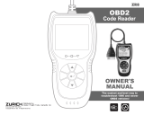
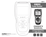
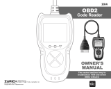
i CAN OBD2
E
Title Page No.
INTRODUCTION
What is OBD? . . . . . . . . . . . . . . . . . . . . . . . . . . . . . . . . . . . . . 1
YOU CAN DO IT! . . . . . . . . . . . . . . . . . . . . . . . . . . . . . . . . . . . . . . . 2
SAFETY PRECAUTIONS
Safety First! . . . . . . . . . . . . . . . . . . . . . . . . . . . . . . . . . . . . . . 3
ABOUT THE CODE READER
Vehicles Covered . . . . . . . . . . . . . . . . . . . . . . . . . . . . . . . . . . 5
Battery Replacement . . . . . . . . . . . . . . . . . . . . . . . . . . . . . . . 6
Adjustments and Settings . . . . . . . . . . . . . . . . . . . . . . . . . . . . 7
CODE READER CONTROLS
Controls and Indicators . . . . . . . . . . . . . . . . . . . . . . . . . . . . . . 10
Display Functions . . . . . . . . . . . . . . . . . . . . . . . . . . . . . . . . . . . 12
ONBOARD DIAGNOSTICS
Computer Engine Controls . . . . . . . . . . . . . . . . . . . . . . . . . . . 14
Diagnostic Trouble Codes (DTCs) . . . . . . . . . . . . . . . . . . . . . . 20
OBD 2 Monitors . . . . . . . . . . . . . . . . . . . . . . . . . . . . . . . . . . . 23
PREPARATION FOR TESTING
Preliminary Vehicle Diagnosis Worksheet . . . . . . . . . . . . . . . . 30
Before You Begin . . . . . . . . . . . . . . . . . . . . . . . . . . . . . . . . . . 33
USING THE CODE READER
Code Retrieval Procedure . . . . . . . . . . . . . . . . . . . . . . . . . . . . 35
Erasing Diagnostic Trouble Codes (DTCs) . . . . . . . . . . . . . . . . 40
I/M Readiness Testing . . . . . . . . . . . . . . . . . . . . . . . . . . . . . . . 42
GLOSSARY
Introduction . . . . . . . . . . . . . . . . . . . . . . . . . . . . . . . . . . . . . . . 49
Glossary of Terms and Abbreviations . . . . . . . . . . . . . . . . . . . 49
WARRANTY AND SERVICING
Limited One Year Warranty . . . . . . . . . . . . . . . . . . . . . . . . . . . 51
Service Procedures . . . . . . . . . . . . . . . . . . . . . . . . . . . . . . . . 51

Introduction
WHAT IS OBD?
CAN OBD2 1
E
WHAT IS OBD?
The CAN OBD2 Code Reader is designed to work on all OBD 2
compliant vehicles. All 1996 and newer vehicles (cars, light
trucks and SUVs) sold in the United States are OBD 2 compliant.
One of the most exciting improvements
in the automobile industry was the addition
of on-board diagnostics (OBD) on vehicles,
or in more basic terms, the computer that
activates the vehicle’s “CHECK ENGINE”
light. OBD 1 was designed to monitor manu-
facturer-specific systems on vehicles built
from 1981 to 1995.Then came the develop-
ment of OBD 2, which is on all
1996 and newer vehicles sold in the
U.S.Like its predecessor, OBD 2 was adopted as part of a government
mandate to lower vehicle emissions.But what makes OBD 2 unique is
its universal application for all late model cars and trucks - domestic
and import.This sophisticated program in the vehicle’s main computer
system is designed to detect failures in a range of systems, and can
be accessed through a universal OBD 2 port, which is usually found
under the dashboard. For all OBD systems, if a problem is found, the
computer turns on the “CHECK ENGINE” light to warn the driver, and
sets a Diagnostic Trouble Code (DTC) to identify where the problem
occurred. A special diagnostic tool, such as the CAN OBD2 Code
Reader, is required to retrieve these codes, which consumers and pro-
fessionals use as a starting point for repairs.
To learn more about vehicle Computer Control Systems and
OBD 2, see COMPUTER ENGINE CONTROLS on page 14.

You Can Do It!
EASY TO USE - EASY TO VIEW - EASY TO DEFINE
2 CAN OBD2
E
Easy To Use ....
■ Connect the Code Reader to the
vehicle’s test connector.
■ Turn the ignition key "On.”
■ Press the LINK button.
Easy To View ....
■ The Code Reader retrieves stored
codes, Freeze Frame data and I/M
Readiness status.
■ Codes, I/M Readiness status and
Freeze Frame data are displayed on the
Code Reader’s LCD display screen.
System status is indicated by LED indi-
cators.
Easy To Define ....
■ Read code definitions from the Code
Reader’s LCD display.
■ View Freeze Frame data.

Safety Precautions
SAFETY FIRST!
CAN OBD2 3
E
SAFETY FIRST!
This manual describes common test procedures used by
experienced service technicians. Many test procedures
require precautions to avoid accidents that can result in
personal injury, and/or damage to your vehicle or test
equipment. Always read your vehicle's service manual and
follow its safety precautions before and during any test or
service procedure. ALWAYS observe the following general
safety precautions:
When an engine is running, it produces carbon monox-
ide, a toxic and poisonous gas.To prevent serious injury
or death from carbon monoxide poisoning, operate the
vehicle ONLY in a well-ventilated area.
To protect your eyes from propelled objects as well as
hot or caustic liquids, always wear approved safety
eye protection.
When an engine is running, many parts (such as the
coolant fan, pulleys, fan belt etc.) turn at high speed.To
avoid serious injury, always be aware of moving parts.
Keep a safe distance from these parts as well as other
potentially moving objects.
Engine parts become very hot when the engine is run-
ning. To prevent severe burns, avoid contact with hot
engine parts.
Before starting an engine for testing or trouble-shoot-
ing, make sure the parking brake is engaged. Put the
transmission in park (for automatic transmission) or
neutral (for manual transmission). Block the drive
wheels with suitable blocks.
Connecting or disconnecting test equipment when the
ignition is ON can damage test equipment and the vehi-
cle's electronic components. Turn the ignition OFF
before connecting the Code Reader to or disconnecting
the Code Reader from the vehicle’s Data Link
Connector (DLC).
To avoid personal injury, instrument damage and/or
damage to your vehicle; do not use the CAN OBD2 Code
Reader before reading this manual.
N
L
D
R
P

Safety Precautions
SAFETY FIRST!
4 CAN OBD2
E
To prevent damage to the on-board computer when tak-
ing vehicle electrical measurements, always use a digi-
tal multimeter with at least 10 megOhms of impedance.
Fuel and battery vapors are highly flammable. To pre-
vent an explosion, keep all sparks, heated items and
open flames away from the battery and fuel / fuel
vapors. DO NOT SMOKE NEAR THE VEHICLE DUR-
ING TESTING.
Don't wear loose clothing or jewelry when working on an
engine. Loose clothing can become caught in the fan,
pulleys, belts, etc.Jewelry is highly conductive, and can
cause a severe burn if it makes contact between a
power source and ground.

About the Code Reader
VEHICLES COVERED
CAN OBD2 5
E
VEHICLES COVERED
The CAN OBD2 Code Reader is designed to work on all OBD 2 com-
pliant vehicles.All 1996 and newer vehicles (cars and light trucks) sold
in the United States are OBD 2 compliant.
Federal law requires that all 1996 and newer cars and light
trucks sold in the United States must be OBD 2 compliant;
this includes all Domestic, Asian and European vehicles.
Some 1994 and 1995 vehicles are OBD 2 compliant. To find out if a
1994 or 1995 vehicle is OBD 2 compliant, check the following:
1. The Vehicle Emissions Control Information (VECI) Label. This
label is located under the hood or by the radiator of most vehicles. If
the vehicle is OBD 2 compliant, the label will state “OBD II Certified.”
2. Government Regulations require that
all OBD 2 compliant vehicles must
have a “common” sixteen-pin Data
Link Connector (DLC).
Some 1994 and 1995 vehicles have 16-pin connectors but
are not OBD 2 compliant. Only those vehicles with a Vehicle
Emissions Control Label stating “OBD II Certified” are OBD 2
compliant.
Data Link Connector (DLC) Location
The 16-pin DLC is usually
located under the instrument
panel (dash), within 12 inches
(300 mm) of center of the
panel, on the driver’s side of
most vehicles.It should be eas-
ily accessible and visible from
a kneeling position outside the
vehicle with the door open.
VEHICLE EMISSION CONTROL INFORMATION
VEHICLE
MANUFACTURER
OBD II
CERTIFIED
ENGINE FAMILY EFN2.6YBT2BA
DISPLACEMENT 2.6L
THIS VEHICLE CONFORMS TO U.S. EPA AND STATE
OF CALIFORNIA REGULATIONS APPLICABLE TO
1999 MODEL YEAR NEW TLEV PASSENGER CARS.
REFER TO SERVICE MANUAL FOR ADDITIONAL INFORMATION
TUNE-UP CONDITIONS: NORMAL OPERATING ENGINE TEMPERATURE,
ACCESSORIES OFF, COOLING FAN OFF, TRANSMISSION IN NEUTRAL
SPARK PLUG
TYPE NGK BPRE-11
GAP: 1.1MM
CATALYST
EXHAUST EMISSIONS STANDARDS STANDARD CATEGORY
CERTIFICATION
IN-USE
TLEV
TLEV INTERMEDIATE
OBD II
CERTIFIED
12345678
910111213141516
NEAR
CENTER
OF DASH
BEHIND
ASHTRAY
LEFT CORNER
OF DASH

About the Code Reader
VEHICLES COVERED / BATTERY REPLACEMENT
6 CAN OBD2
E
On some Asian and European vehicles the DLC is located
behind the “ashtray” (the ashtray must be removed to access
it) or on the far left corner of the dash. If the DLC cannot be
located, consult the vehicle’s service manual for the location.
BATTERY REPLACEMENT
1. Locate the battery cover on the back of the Code Reader.
2. Slide the battery cover off (use your fingers).
3. Replace batteries with three AA-size batteries (for longer life, use
Alkaline-type batteries).
4. Reinstall the battery cover on the back of the Code Reader.
Language Selection After Battery Installation
There are two versions of the Code Reader: English/Spanish and
English/French.The first time the unit is turned on (after the batteries
are installed or replaced), you must select the desired display lan-
guage, as follows:
1. Press the POWER/LINK button to turn the Code Reader “ON.”
■ The Select Language screen displays.
2. Use the UP and DOWN but-
tons, as necessary, to highlight the
desired display language.
3.
When the desired display language is
selected, press the ENTER/FF but-
ton to confirm your selection.
■ The selected language will remain in
the Code Reader’s memory as long
as the batteries are not removed. If
the batteries are removed (or go
dead), the language selection will be
lost from the Code Reader’s memory
and must be reset again using steps
1 through 3, above.
■ After the initial language selection is performed, it as well as
other settings can be changed as desired. See ADJUSTMENTS
AND SETTINGS on page 7 for further instructions.

About the Code Reader
ADJUSTMENTS AND SETTINGS
CAN OBD2 7
E
ADJUSTMENTS AND SETTINGS
The CAN OBD2 Code Reader lets you make several adjustments and
settings to configure the Code Reader for your particular needs. The
following adjustments and settings can be made:
■ Adjust Brightness: Adjusts the brightness of the LCD display
screen.
■ Demo Mode: Sample data kept in the Code Reader’s memory to
use as examples and for demonstration purposes.
■ Select Language: Sets the display language for the Code Reader
to English/Spanish or English/French.
■ Unit of Measure: Sets the Unit of Measure for the Code Reader’s
display to USA or metric.
Adjustments and settings can be made only when the Code
Reader is NOT connected to a vehicle.
To enter the MENU Mode:
1. With the Code Reader “off”, press and
hold
the UP button, then press and
release the POWER/LINK button.
■ The adjustments and setting MENU
displays.
2. Release the UP button.
DO NOT release the UP button until the adjustments and
settings MENU is visible on the display.
3. Make adjustments and settings as described in the following para-
graphs.
Adjusting Display Brightness
1. Use the UP and DOWN but-
tons, as necessary, to highlight Adjust
Brightness in the MENU, then press
the ENTER/FF button.
■ The Adjust Brightness screen dis-
plays.
■ The Brightness field shows the cur-
rent brightness setting, from 0 to 43.
2. Press the UP button to decrease
the brightness of the LCD display (make
the display darker).

About the Code Reader
ADJUSTMENTS AND SETTINGS
8 CAN OBD2
E
3. Press the DOWN button to increase the brightness of the LCD
display (make the display lighter).
4. When the desired brightness is obtained, press the ENTER/FF
button to save your changes and return to the MENU.
Selecting the Display Language
1. Use the UP and DOWN but-
tons, as necessary, to highlight Select
Language in the MENU, then press the
ENTER/FF button.
■ The Select Language screen dis-
plays.
■ The currently selected display
Language is highlighted.
2. Press the UP or DOWN button,
as necessary, to highlight the desired
display language.
3. When the desired display language is
highlighted, press the ENTER/FF
button to save your changes and return
to the MENU.
Setting the Unit of Measure
1. Use the UP and DOWN but-
tons, as necessary, to highlight Unit of
Measure in the MENU, then press the
ENTER/FF button.
2. Press the UP or DOWN button,
as necessary, to highlight the desired
Unit of Measure.
3. When the desired Unit of Measure
value is selected, press the ENTER/FF
button to save your changes.

About the Code Reader
ADJUSTMENTS AND SETTINGS
CAN OBD2 9
E
Demo Mode
1. Use the UP and DOWN but-
tons, as necessary, to highlight Demo
Mode in the MENU, then press the
ENTER/FF button.
2. The Code Reader enters the Demo
Mode.
3. Demo Mode demonstrates examples of Generic and Enhanced
(Manufacturer Speciific) Diagnostic Trouble Codes, code definitions,
Freeze Frame data and I/M Readiness status.
■ Use Demo Mode to familiarize yourself with Code Reader oper-
ation, vehicle diagnostic data and/or for demonstration purposes.
4. To exit Demo Mode, turn the Code Reader off by pressing the
POWER/LINK button.
Exiting the MENU Mode
1. Use the UP and DOWN buttons, as necessary, to highlight
Menu Exit in the MENU, then press the ENTER/FF button.
■ The LCD display returns to the DTC screen.
Changes made to Brightness, Language and Unit of
Measure will remain in the Code Reader’s memory as long
as the batteries are not removed.If the batteries are removed
(or go dead), the settings will be lost from the Code Reader’s
memory, and they must be reset again.

Code Reader Controls
CONTROLS AND INDICATORS
10 CAN OBD2
E
CONTROLS AND INDICATORS
See Figure 1 for the locations of items 1 through 11, below.
1. ERASE button - Erases Diagnostic Trouble Codes (DTCs),
and “Freeze Frame” data from your vehicle’s computer, and resets
Monitor status.
2. DTC SCROLL button - Displays the DTC View screen and/or
scrolls the LCD display to view DTCs when more than one DTC is
present.
3. POWER/LINK button - When the Code Reader IS NOT
connected to a vehicle, turns the Code Reader “On” and “Off”. When
the Code Reader is connected to a vehicle, links the Code Reader to
the vehicle’s PCM to retrieve diagnostic data from the computer’s
memory.
4. ENTER/FREEZE FRAME button - When in MENU mode,
confirms the selected option or value. When retrieving and viewing
DTCs, displays Freeze Frame data for the highest priority code.
1
6
7
2
5
3
9
8
4
10
11
Figure 1. Controls and Indicators

Code Reader Controls
CONTROLS AND INDICATORS
CAN OBD2 11
E
5. DOWN button - When in MENU mode, scrolls DOWN through
the menu and submenu selection options. When retrieving and view-
ing DTCs, scrolls down through the current display screen to display
any additional data.
6. UP button - When in MENU mode, scrolls UP through the
menu and submenu selection options. When retrieving and viewing
DTCs, scrolls ups through the current display screen to display any
additional data.
7. GREEN LED - Indicates that all engine systems are running nor-
mally (all Monitors on the vehicle are active and performing their diag-
nostic testing, and no DTCs are present).
8. YELLOW LED - Indicates there is a possible problem.A “Pending”
DTC is present and/or some of the vehicle’s emission monitors have
not run their diagnostic testing.
9. RED LED - Indicates there is a problem in one or more of the vehi-
cle’s systems.The red LED is also used to show that DTC(s) are pres-
ent. DTCs are shown on the Code Reader’s LCD display. In this case,
the Multifunction Indicator (“Check Engine”) lamp on the vehicle’s
instrument panel will light steady on.
10. LCD Display - Displays settings Menu and submenus, test
results, Code Reader functions and Monitor status information. See
DISPLAY FUNCTIONS, on next page, for more details.
11. CABLE - Connects the Code Reader to the vehicle’s Data Link
Connector (DLC).

Code Reader Controls
DISPLAY FUNCTIONS
12 CAN OBD2
E
DISPLAY FUNCTIONS
See Figure 2 for the locations of items 1 through 16, below.
1. I/M MONITOR STATUS field - Identifies the I/M Monitor status area.
2. Monitor icons - Indicate which Monitors are supported by the vehi-
cle under test, and whether or not the associated Monitor has run
its diagnostic testing (Monitor status).When a Monitor icon is solid,
it indicates that the associated Monitor has completed its diagnos-
tic testing.When a Monitor icon is flashing, it indicates that the vehi-
cle supports the associated Monitor, but the Monitor has not yet run
its diagnostic testing.
3. Vehicle icon - Indicates whether or not the Code Reader is
being properly powered through the vehicle’s Data Link Connector
(DLC). A visible icon indicates that the Code Reader is being pow-
ered through the vehicle’s DLC connector.
4. Link icon - Indicates whether or not the Code Reader is com-
municating (linked) with the vehicle’s on-board computer.When vis-
ible, the Code Reader is communicating with the computer. If the
Link icon is not visible, the Code Reader is not communicating with
the computer.
5. Computer icon - When this icon is visible it indicates that the
Code Reader is linked to a personal computer.An optional “PC Link
Kit” is available that makes it possible to upload retrieved data to a
personal computer.
6. Code Reader Internal Battery icon - When visible, indicates
the Code Reader batteries are “low” and should be replaced.
7. DTC Display Area - Displays the Diagnostic Trouble Code (DTC)
number. Each fault is assigned a code number that is specific to
that fault.
4
3
21
10
11 12
5
8
9
13
15
14
6
7
Figure 2. Display Functions

Code Reader Controls
DISPLAY FUNCTIONS
CAN OBD2 13
E
8. Test Data Display Area - Displays DTC definitions, Freeze Frame
data, and other pertinent test information messages.
9. MIL icon - Indicates the status of the Malfunction Indicator Lamp
(MIL).The MIL icon is visible only when a DTC has commanded the
MIL on the vehicle’s dashboard to light.
10. CODE icon - Identifies the Code Number Sequence display area.
11. PENDING icon - Indicates the currently displayed DTC is a
“Pending” code.
12. Code Number Sequence - The Code Reader assigns a
sequence number to each DTC that is present in the computer’s
memory, starting with “01.” This number indicates which code is
currently displayed. Code number “01” is always the highest prior-
ity code, and the one for which “Freeze Frame” data has been
stored.
If “01” is a “Pending” code, there may or may not be
“Freeze Frame” data stored in memory.
13. Code Enumerator - Indicates the total number of codes retrieved
from the vehicle’s computer.
14. Generic DTC icon - When visible, indicates that the currently
displayed DTC is a “generic” or universal code.
15. Enhanced DTC icon - When visible, indicates that the currently
displayed DTC is a Manufacturer Specific Code.

14 CAN OBD2
E
Onboard Diagnostics
COMPUTER ENGINE CONTROLS
COMPUTER ENGINE CONTROLS
The Introduction of Electronic Engine Controls
As a result of increased air pollution (smog) in large
cities, such as Los Angeles, the California Air Resources
Board (CARB) and the Environmental Protection Agency
(EPA) set new regulations and air pollution standards to
deal with the problem. To further complicate matters, the
energy crisis of the early 1970s caused a sharp increase in
fuel prices over a short period. As a result, vehicle manufac-
turers were not only required to comply with the new emis-
sions standards, they also had to make their vehicles more fuel-
efficient. Most vehicles were required to meet a miles-per-gallon
(MPG) standard set by the U.S. Federal Government.
Precise fuel delivery and spark timing are needed to reduce vehicle
emissions.Mechanical engine controls in use at the time (such as igni-
tion points, mechanical spark advance and the carburetor) responded
too slowly to driving conditions to properly control fuel delivery and
spark timing. This made it difficult for vehicle manufacturers to meet
the new standards.
A new Engine Control System had to be designed and integrated with
the engine controls to meet the stricter standards.The new system had
to:
■ Respond instantly to supply the proper mixture of air and fuel for
any driving condition (idle, cruising, low-speed driving, high-speed
driving, etc.).
■ Calculate instantly the best time to “ignite” the air/fuel mixture for
maximum engine efficiency.
■ Perform both these tasks without affecting vehicle performance or
fuel economy.
Vehicle Computer Control Systems can perform millions of calcula-
tions each second.This makes them an ideal substitute for the slower
mechanical engine controls. By switching from mechanical to elec-
tronic engine controls, vehicle manufacturers are able to control fuel
delivery and spark timing more precisely. Some newer Computer
Control Systems also provide control over other vehicle functions,
such as transmission, brakes, charging, body, and suspension sys-
tems.
Electronic Computer Control Systems make it possible
for vehicle manufacturers to comply with the tougher emis-
sions and fuel efficiency standards mandated by
State and Federal Governments.

CAN OBD2 15
E
Onboard Diagnostics
COMPUTER ENGINE CONTROLS
The Basic Engine Computer Control System
The on-board computer is the heart of the Computer
Control System.The computer contains several programs
with preset reference values for air/fuel ratio, spark or igni-
tion timing, injector pulse width, engine speed, etc.
Separate values are provided for various driving conditions,
such as idle, low speed driving, high-speed driving, low load,
or high load. The preset reference values represent the ideal
air/fuel mixture, spark timing, transmission gear selection,
etc., for any driving condition. These values are programmed
by the vehicle manufacturer, and are specific to each vehicle model.
Most on-board computers are located inside the vehicle behind the
dashboard, under the passenger’s or driver’s seat, or behind the right
kick panel. However, some manufacturers may still position it in the
engine compartment.
Vehicle sensors, switches, and actuators are located throughout the
engine, and are connected by electrical wiring to the on-board
computer. These devices include oxygen sensors, coolant tempera-
ture sensors, throttle position sensors, fuel injectors, etc. Sensors and
switches are input devices.They provide signals representing current
engine operating conditions to the computer. Actuators are output
devices. They perform actions in response to commands received
from the computer.
The on-board computer receives information inputs from sensors and
switches located throughout the engine.These devices monitor critical
engine conditions such as coolant temperature, engine speed, engine
load, throttle position, air/fuel ratio etc.
The Computer Control System consists of an on-board
computer and several related control devices (sensors,
switches, and actuators).
OUTPUT DEVICES
Fuel Injectors
Idle Air Control
EGR Valve
Ignition Module
On-Board
Computer
INPUT DEVICES
Coolant Temperature Sensor
Throttle Position Sensor
Fuel Injectors
INPUT DEVICES
Oxygen Sensors
TYPICAL COMPUTER
CONTROL SYSTEM

16 CAN OBD2
E
Onboard Diagnostics
COMPUTER ENGINE CONTROLS
The computer compares the values received from these sensors with
its preset reference values, and makes corrective actions as needed
so that the sensor values always match the preset reference values for
the current driving condition. The computer makes adjustments by
commanding other devices such as the fuel injectors, idle air control,
EGR valve or Ignition Module to perform these actions.
Vehicle operating conditions are constantly changing. The computer
continuously makes adjustments or corrections (especially to the
air/fuel mixture and spark timing) to keep all the engine systems oper-
ating within the preset reference values.
On-Board Diagnostics - First Generation (OBD 1)
Beginning in 1988, California’s Air Resources Board
(CARB), and later the Environmental Protection Agency
(EPA) required vehicle manufacturers to include a self-
diagnostic program in their on-board computers. The pro-
gram would be capable of identifying emissions-related faults
in a system. The first generation of Onboard Diagnostics
came to be known as OBD 1.
OBD 1 is a set of self-testing and diagnostic instructions pro-
grammed into the vehicle’s on-board computer. The programs are
specifically designed to detect failures in the sensors, actuators,
switches and wiring of the various vehicle emissions-related systems.
If the computer detects a failure in any of these components or sys-
tems, it lights an indicator on the dashboard to alert the driver.The indi-
cator lights only when an emissions-related problem is detected.
The computer also assigns a numeric code for each specific problem
that it detects, and stores these codes in its memory for later retrieval.
These codes can be retrieved from the computer’s memory with the
use of a “Code Reader” or a “Scan Tool.”
With the exception of some 1994 and 1995 vehicles,
most vehicles from 1982 to 1995 are equipped with
some type of first generation On-Board Diagnostics.

CAN OBD2 17
E
Onboard Diagnostics
COMPUTER ENGINE CONTROLS
On-Board Diagnostics - Second Generation (OBD 2)
In addition to performing all the func-
tions of the OBD 1 System, the OBD 2
System has been enhanced with new
Diagnostic Programs.These programs
closely monitor the functions of vari-
ous emissions-related components
and systems (as well as other sys-
tems) and make this information readily available (with
the proper equipment) to the technician for evaluation.
The California Air Resources Board (CARB) conducted
studies on OBD 1 equipped vehicles. The information that
was gathered from these studies showed the following:
■ A large number of vehicles had deteriorating or degraded
emissions-related components. These components were
causing an increase in emissions.
■ Because OBD 1 systems only detect failed components, the
degraded components were not setting codes.
■ Some emissions problems related to degraded components only
occur when the vehicle is being driven under a load. The emission
checks being conducted at the time were not performed under sim-
ulated driving conditions. As a result, a significant number of vehi-
cles with degraded components were passing Emissions Tests.
■ Codes, code definitions, diagnostic connectors, communication
protocols and emissions terminology were different for each manu-
facturer. This caused confusion for the technicians working on dif-
ferent make and model vehicles.
To address the problems made evident by this study, CARB and the EPA
passed new laws and standardization requirements.These laws required
that vehicle manufacturers to equip their new vehicles with devices capa-
ble of meeting all of the new emissions standards and regulations.It was
also decided that an enhanced on-board diagnostic system, capable of
addressing all of these problems, was needed.This new system is known
as “On-Board Diagnostics Generation Two (OBD 2).” The primary
objective of the OBD 2 system is to comply with the latest regulations and
emissions standards established by CARB and the EPA.
The Main Objectives of the OBD 2 System are:
■ To detect degraded and/or failed emissions-related components or
systems that could cause tailpipe emissions to exceed by 1.5 times
the Federal Test Procedure (FTP) standard.
■ To expand emissions-related system monitoring.This includes a set
of computer run diagnostics called Monitors.Monitors perform diag-
nostics and testing to verify that all emissions-related components
and/or systems are operating correctly and within the manufactur-
er’s specifications.
The OBD 2 System is
an enhancement of the
OBD 1 System.

18 CAN OBD2
E
Onboard Diagnostics
COMPUTER ENGINE CONTROLS
■ To use a standardized Diagnostic Link Connector (DLC) in all vehi-
cles. (Before OBD 2, DLCs were of different shapes and sizes.)
■ To standardize the code numbers, code definitions and language
used to describe faults. (Before OBD 2, each vehicle manufacturer
used their own code numbers, code definitions and language to
describe the same faults.)
■ To expand the operation of the Malfunction Indicator Lamp (MIL).
■ To standardize communication procedures and protocols between
the diagnostic equipment (Scan Tools, Code Readers, etc.) and the
vehicle’s on-board computer.
OBD 2 Terminology
The following terms and their definitions are related to OBD 2 systems.
Read and reference this list as needed to aid in the understanding of
OBD 2 systems.
■ Powertrain Control Module (PCM) - The PCM is the OBD 2
accepted term for the vehicle’s “on-board computer.” In addition to
controlling the engine management and emissions systems, the
PCM also participates in controlling the powertrain (transmission)
operation. Most PCMs also have the ability to communicate with
other computers on the vehicle (ABS, ride control, body, etc.).
■ Monitor - Monitors are “diagnostic routines” programmed into the
PCM.The PCM utilizes these programs to run diagnostic tests, and
to monitor operation of the vehicle’s emissions-related components
or systems to ensure they are operating correctly and within the
vehicle’s manufacturer specifications. Currently, up to eleven
Monitors are used in OBD 2 systems. Additional Monitors will be
added as the OBD 2 system is further developed.
Not all vehicles support all eleven Monitors.
■ Enabling Criteria - Each Monitor is designed to test and monitor
the operation of a specific part of the vehicle’s emissions system
(EGR system, oxygen sensor, catalytic converter, etc.). A specific
set of “conditions” or “driving procedures” must be met before the
computer can command a Monitor to run tests on its related sys-
tem. These “conditions” are known as “Enabling Criteria.” The
requirements and procedures vary for each Monitor.Some Monitors
only require the ignition key to be turned “On” for them to run and
complete their diagnostic testing. Others may require a set of com-
plex procedures, such as, starting the vehicle when cold, bringing it
to operating temperature, and driving the vehicle under specific
conditions before the Monitor can run and complete its diagnostic
testing.
/