Page is loading ...

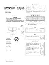
OPERATION
© 2003 DESA Specialty Products™ 595-5767-02
* resets to Auto Mode at dawn.
MANUAL MODE
ON-TIME
10 5 1 TEST
10 5 1 TEST
ON-TIME
TEST
... back on.
AUTO
1 Second OFF
then...
Move ON-TIME Switch to
1, 5 or 10 minutes
Mode Switching Summary
Flip light switch off
for one second then
back on*
MANUAL MODE
AUTO
TEST
Requirements
• The Light Control requires 120-volts AC.
• If you want to use Manual Mode, the control must be
wired through a switch.
• Some codes require installation by a qualified
electrician.
• This product is intended for use with the enclosed
gasket and with a junction box marked for use in wet
locations.
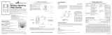
Model SL-5412
Light Control
Sensor
Cover
Plate
Lamp Holders
2 Wire
Connectors
6 Screws
(3 sizes included)
Gasket
2 Shells
Features
• Turns on lighting when motion is detected.
• Automatically turns lighting off.
• Photocell keeps the lighting off during daylight hours.
• LED indicates motion was sensed (day or night).
Motion Sensor Light
Control for Canadian
Tire
* If you get confused while switching modes, turn the
power off for one minute, then back on. After the
calibration time the control will be in the AUTO mode.
Note: When first turned on wait about 1
1
/
2
minutes for
the circuitry to calibrate.
Mounting Bolt
Mounting Strap
Plastic Hanger
Rubber Plug
This package includes:
Mode: On-Time: Works: Day Night
Test 5 Sec x x
Auto 1, 5, 10 min. x
Manual Until Dawn* x
Put the ON-TIME switch on the bottom
of the sensor in the TEST position.
Put the ON-TIME switch in the 1, 5
or 10 minute position.
Manual mode only works at night be-
cause daylight returns the sensor to
AUTO.
Flip the light switch off for one second
then back on to toggle between AUTO
and MANUAL MODE.
Manual mode works only with the ON-
TIME switch in the 1, 5, or 10 position.

2
595-5767-02
INSTALLATION
For easy installation, select an existing light with a wall
switch for replacement.
WIRE THE LIGHT CONTROL.
❒ Turn power off at the fuse or circuit breaker.
❒ Remove the existing light fixture.
❒ Install the mounting strap as shown using two
screws that fit your junction box.
❒ The plastic hanger can be used to hold the fixture
while wiring. The small end of the plastic hanger
can be threaded through the hole in the center of the
cover plate. The small end then goes into one of the
slots on the mounting strap.
❒ Route the Light Control’s wires through the large
gasket holes.
❒ Twist the junction box wires and fixture wires together
as shown. Secure with wire connectors.
MOUNT THE LIGHT CONTROL.
❒ Align the Light Control cover plate and cover plate
gasket. Secure with the mounting bolt.
❒ Align the three slots in the decorative shell with the
lamp holder pins. Push the shell in and then twist
clockwise to lock. Repeat for other shell.
White to White
❒ Push the Rubber Plug firmly into place.
❒ If a wet location junction box was not used, caulk the
wall plate mounting surface with silicone weather
sealant.
❒ Adjust the lamp holders by loosening the lock nuts
but do not rotate the lamp holders more than 180°
from the factory setting. When screwing in the
floodlamps, do not overtighten.
Black to Black
Junction box ground wire to
green ground screw on fixture.
Gasket
For eave mount only:
❒ Swing the sensor head towards the clamp screw
joint.
If the sensor pops out of the ball joint, loosen the
clamp screw and push the sensor back into the ball
joint. Tighten the clamp screw when done.
❒ Then rotate the sensor head clockwise 180° so
the controls face down.
Controls
Wall Mount
Eave Mount
For under eave installation, the sensor head must
be rotated as shown in the next two steps for proper
operation and to avoid the risk of electrical shock.
Shell Slot
Mounting
Strap
Mounting
Bolt
Controls
Controls
Clamp
Screw
Lock Nut
To avoid water damage and electrical shock,
keep lamp holders 30° below horizontal.
Keep lamps at least
1" (2.5 cm) from the
sensor. Do not al-
low the lamps to
block the lens.
Lens
Rubber
Plug

3
595-5767-02
Motion
Motion
TEST AND ADJUSTMENT
❒ Turn on the circuit breaker and light switch.
Least Sensitive Most Sensitive
Sensor
The detector is most sensitive to motion across its field
of view.
❒ Loosen the clamp screw in
the sensor ball joint and gen-
tly rotate the sensor.
❒ Walk through the coverage
area noting where you are
when the lights turn on (also,
the LED will flash several times
when motion is detected).
Move the sensor head up,
down, or sideways to change
the coverage area. Keep the
sensor at least 1" (2.5 cm)
away from the lamps.
❒ Adjust the RANGE as
needed. RANGE set too high
may increase false triggering.
❒ Secure the sensor head by
tightening the clamp screw.
Do not overtighten the screw.
❒ Set the amount of TIME you
want the lights to stay on after motion is detected (1,
5, or 10 minutes).
Clamp
Screw
Ball
Joint
Aim Sensor
Down for Short
Coverage
Aim Sensor
Higher for Long
Coverage
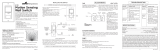
SPECIFICATIONS
Range . . . . . . . . . . . . Up to 70 ft. (21 m) [varies with
surrounding temperature].
Sensing Angle . . . . . . Up to 180°
Electrical Load. . . . . . Up to 300 Watts Maximum In-
candescent [Up to 150 Watts
Maximum each lamp holder.]
Power Requirements. 120 VAC, 60 Hz
Operating Modes. . . . TEST, AUTO and MANUAL
MODE
Time Delay . . . . . . . . 1 , 5, 10 minutes
DESA Specialty Products™ reserves the right to discon-
tinue products and to change specifications at any time
without incurring any obligation to incorporate new fea-
tures in products previously sold.
Maximum Range Maximum
Coverage Angle
NOTE: Sensor has about 1
1
/
2
minutes warm up
period before it will detect motion. When first
turned on, wait about 1
1
/
2
minutes.
RANGE
10 5 1 TEST
ON-TIME
Bottom of Sensor
Avoid aiming the control at:
• Objects that change temperature rapidly, such as
heating vents and air conditioners. These heat
sources could cause false triggering.
• Areas where pets or traffic may trigger the control.
• Nearby large, light-colored objects reflecting light
may trigger the shut-off feature. Do not point other
lights at the sensor.
180°
MIN MAX
70 ft.
(21 m)
8 ft.
(2.4 m)
❒ Turn the RANGE control to the mid position and the
ON-TIME control to the TEST position.

4
595-5767-02
POSSIBLE CAUSE
1. A flood lamp is positioned too close to
the sensor or pointed at nearby ob-
jects that cause heat to trigger the
sensor.
(Reposition the lamp away
from the sensor or nearby objects.)
2. Light Control is pointed toward a heat
source like an air vent, dryer vent, or
brightly-painted heat-reflective sur-
face.
(Reposition sensor.)
3. Light Control is in Manual Mode.
(Switch to Auto.)
1. Heat or light from the lamps may be
turning the Light Control on and off.
(Reposition the lamps away from the
sensor.)
2. Heat being reflected from other ob-
jects may be affecting the sensor.
(Reposition sensor.)
3. Light Control is in the Test mode and
warming up.
(Flashing is normal un-
der these conditions.)
4. Light may be leaking through the
floodlamp reflectors.
(Make sure the
metal lamp protectors are installed.)
SYMPTOM
Lights stay on
continuously.
Lights flash
on and off.
SYMPTOM
Lights will not
come on.
Lights come
on in daylight.
Lights come
on for no
apparent
reason.
POSSIBLE CAUSE
1. Light switch is turned off.
2. Flood light is loose or burned out.
3. Fuse is blown or circuit breaker is
turned off.
4. Daylight turn-off is in effect
(recheck
after dark)
.
5. Incorrect circuit wiring, if this is a new
installation.
6. Re-aim the sensor to cover desired
area.
1. Light Control may be installed in a
relatively dark location.
2. Light Control is in Test.
(Set control
switch to an ON-TIME position.)
1. Light Control may be sensing small
animals or automobile traffic
(re-aim
sensor)
.
2. Range is set too high.
(Reduce
Range.)
TROUBLESHOOTING GUIDE
If you experience a problem, follow this guide.
See your Canadian Tire retailer for warranty information.
/