JVC DLA-RS1 User manual

Category
Projectors
Type
User manual

This manual is also suitable for

Printed in Japan
0308TTH-SW-VP© 2008 Victor Company of Japan, Limited
D-ILA HOME THEATER PROJECTOR
PROJECTEUR CINÉMA MAISON D-ILA
SISTEMA DE CINE EN CASA D-ILA
DLA-RS1
DLA-RS1
Getting Started Preparation Basic Operation Settings Troubleshooting Others
LCT2440-001B
D-ILA HOME THEATER PROJECTOR
PROJECTEUR CINÉMA MAISON D-ILA
SISTEMA DE CINE EN CASA D-ILA
INSTRUCTIONS
MANUEL D’INSTRUCTIONS
MANUAL DE INSTRUCCIONES
DLA-RS1
ENGLISH FRANÇAIS ESPAÑOL
DLA-RS1E_MainCover426x297.fm Page 1 Monday, March 24, 2008 1:25 PM
1
2
Getting Started
Safety Precautions
IIMPORTANT INFORMATION
About the installation place
Do not install the projector in a place that cannot support
its weight securely.
If the installation place is not sturdy enough, the projector
could fall or overturn, possibly causing personal injury.
IMPORTANT SAFEGUARDS
Electrical energy can perform many useful functions. This
unit has been engineered and manufactured to assure
your personal safety. But IMPROPER USE CAN RESULT
IN POTENTIAL ELECTRICAL SHOCK OR FIRE
HAZARD. In order not to defeat the safeguards
incorporated into this product, observe the following basic
rules for its installation, use and service. Please read
these Important Safeguards carefully before use.
- All the safety and operating instructions should be read
before the product is operated.
- The safety and operating instructions should be retained
for future reference.
- All warnings on the product and in the operating
instructions should be adhered to.
- All operating instructions should be followed.
- Place the projector near a wall outlet where the plug can
be easily unplugged.
- Unplug this product from the wall outlet before cleaning.
Do not use liquid cleaners or aerosol cleaners. Use a
damp cloth for cleaning.
- Do not use attachments not recommended by the product
manufacturer as they may be hazardous.
- Do not use this product near water. Do not use
immediately after moving from a low temperature to high
temperature, as this causes condensation, which may
result in fire, electric shock, or other hazards.
- Do not place this product on an unstable cart, stand, or
table. The product may fall, causing serious injury to a
child or adult, and serious damage to the product. The
product should be mounted according to the
manufacturer’s instructions, and should use a mount
recommended by the manufacturer.
- When the product is used on a cart,
care should be taken to avoid quick
stops, excessive force, and uneven
surfaces which may cause the product
and cart to overturn, damaging
equipment or causing possible injury to
the operator.
- Slots and openings in the cabinet are
provided for ventilation. These ensure
reliable operation of the product and protect it from
overheating. These openings must not be blocked or
covered. (The openings should never be blocked by
placing the product on bed, sofa, rug, or similar surface. It
should not be placed in a built-in installation such as a
bookcase or rack unless proper ventilation is provided and
the manufacturer’s instructions have been adhered to.)
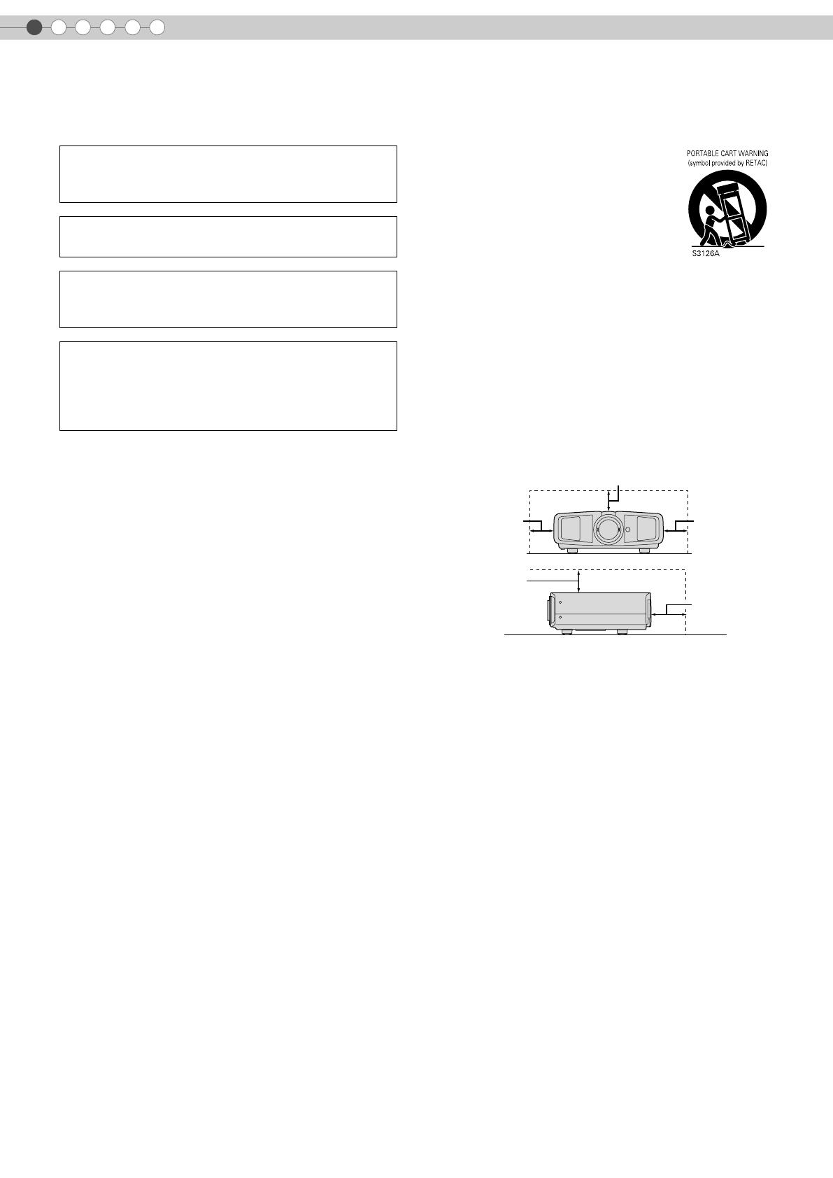
- To allow better heat dissipation, keep a clearance between
this unit and its surrounding as shown below. When this
unit is enclosed in a space of dimensions as shown below,
use an air-conditioner so that the internal and external
temperatures are the same.
- This product should be operated only with the type of
power source indicated on the label. If you are not sure of
the type of power supply to your home, consult your
product dealer or local power company.
- This product is equipped with a three-wire plug. This plug
will fit only into a grounded power outlet. If you are unable
to insert the plug into the outlet, contact your electrician to
install the proper outlet. Do not defeat the safety purpose
of the grounded plug.
- Power-supply cords should be routed so that they are not
likely to be walked on or pinched by items placed upon or
against them. Pay particular attention to cords at doors,
plugs, receptacles, and the point where they exit from the
product.
- For added protection of this product during a lightning
storm, or when it is left unattended and unused for long
periods of time, unplug it from the wall outlet and
disconnect the cable system. This will prevent damage to
the product due to lightning and power line surges.
- Do not overload wall outlets, extension cords, or
convenience receptacles on other equipment as this can
result in a risk of fire or electric shock.
- Never push objects of any kind into this product through
openings as they may touch dangerous voltage points or
short out parts that could result in a fire or electric shock.
Never spill liquid of any kind on the product.
- Do not attempt to service this product yourself as opening
or removing covers may expose you to dangerous
voltages and other hazards. Refer all service to qualified
service personnel.
WARNING:
TO PREVENT FIRE OR SHOCK HAZARDS, DO NOT
EXPOSE THIS APPLIANCE TO RAIN OR MOISTURE.
WARNING:
THIS APPARATUS MUST BE EARTHED.
CAUTION:
To reduce the risk of electric shock, do not remove
cover. Refer servicing to qualified service personnel.
MACHINE NOISE INFORMATION (Germany only)
Changes Machine Noise Information Ordinance 3.
GSGV, January 18, 1991: The sound pressure level at
the operator position is equal or less than 70 dB (A)
according to ISO 7779.
150 mm and above
300 mm
and above
150 mm
and above
300 mm
and above
200 mm
and above
DLA-RS1E_EN.book Page 2 Tuesday, February 26, 2008 10:43 AM
3
Getting Started Preparation Basic Operation Settings Troubleshooting Others
ENGLISH
-
Unplug this product from the wall outlet and refer service to
qualified service personnel under the following conditions:
a) When the power supply cord or plug is damaged.
b) If liquid has been spilled, or objects have fallen on the product.
c) If the product has been exposed to rain or water.
d) If the product does not operate normally by following the
operating instructions. Adjust only those controls that are
covered by the Operation Manual, as an improper adjustment
of controls may result in damage and will often require
extensive work by a qualified technician to restore the product
to normal operation.
e) If the product has been dropped or damaged in any way.
f) When the product exhibits a distinct change in performance -
this indicates a need for service.
- When replacement parts are required, be sure the service
technician has used replacement parts specified by the
manufacturer or with same characteristics as the original
part. Unauthorized substitutions may result in fire, electric
shock, or other hazards.
-
Upon completion of any service or repairs to this product,
ask the service technician to perform safety checks to
determine that the product is in proper operating condition.
- The product should be placed more than one foot away
from heat sources such as radiators, heat registers,
stoves, and other products (including amplifiers) that
produce heat.
- When connecting other products such as VCR’s, and DVD
players, you should turn off the power of this product for
protection against electric shock.
- Do not place combustibles behind the cooling fan. For
example, cloth, paper, matches, aerosol cans or gas
lighters that present special hazards when over heated.
- Do not look into the projection lens while the illumination
lamp is turned on. Exposure of your eyes to the strong
light can result in impaired eyesight.
- Do not look into the inside of this unit through vents
(ventilation holes), etc. Do not look at the illumination lamp
directly by opening the cabinet while the illumination lamp
is turned on. The illumination lamp also contains ultraviolet
rays and the light is so powerful that your eyesight can be
impaired.
- Do not drop, hit, or damage the light-source lamp (lamp
unit) in any way. It may cause the light-source lamp to
break and lead to injuries. Do not use a damaged light
source lamp. If the light-source lamp is broken, ask your
dealer to repair it. Fragments from a broken light-source
lamp may cause injuries.
- The light-source lamp used in this projector is a high
pressure mercury lamp. Be careful when disposing of the
lightsource lamp. If anything is unclear, please consult
your dealer.
- Do not ceiling-mount the projector to a place which tends
to vibrate; otherwise, the attaching fixture of the projector
could be broken by the vibration, possibly causing it to fall
or overturn, which could lead to personal injury.
- Use only the accessory cord designed for this product to
prevent shock.
*DO NOT allow any unqualified person to install the
unit.
Be sure to ask your dealer to install the unit (e.g.
attaching it to the ceiling) since special technical
knowledge and skills are required for installation. If
installation is performed by an unqualified person, it
may cause personal injury or electrical shock.
DLA-RS1E_EN.book Page 3 Tuesday, February 26, 2008 10:43 AM
4
Safety Precautions (Continued)
1
Getting Started
POWER CONNECTION
The power supply voltage rating of this product is
AC110 V – AC240 V. Use only the power cord
designated by our dealer to ensure Safety and EMC.
Ensure that the power cable used for the projector is the
correct type for the AC outlet in your country. Consult
your product dealer.
Power cord
WARNING:
Do not cut off the main plug from this equipment.
If the plug fitted is not suitable for the power points in
your home or the cable is too short to reach a power
point, then obtain an appropriate safety approved
extension lead or adapter or consult your dealer.
If nonetheless the mains plug is cut off, dispose of the
plug immediately, to avoid a possible shock hazard by
inadvertent connection to the main supply. If a new main
plug has to be fitted, then follow the instruction given
below.
WARNING:
THIS APPARATUS MUST BE EARTHED.
IMPORTANT:
The wires in the mains lead on this product are coloured
in accordance with the following cord:
Green-and-yellow : Earth
Blue : Neutral
Brown : Live
As these colours may not correspond with the coloured
making identifying the terminals in your plug, proceed
as follows:
The wire which is coloured green-and-yellow must be
connected to the terminal which is marked M with the
letter E or the safety earth or coloured green or green-
and-yellow.
The wire which is coloured blue must be connected to
the terminal which is marked with the letter N or
coloured black.
The wire which is coloured brown must be connected to
the terminal which is marked with the letter L or
coloured red.
DLA-RS1E_EN.book Page 4 Tuesday, February 26, 2008 10:43 AM
5
Getting Started Preparation Basic Operation Settings Troubleshooting Others
ENGLISH
Dear Customer,
This apparatus is in conformance with the valid European directives and standards regarding electromagnetic
compatibility and electrical safety.
European representative of Victor Company of Japan, Limited is:
JVC Technical Services Europe GmbH
Postfach 10 05 04
61145 Friedberg
Germany
DLA-RS1E_EN.book Page 5 Monday, March 24, 2008 1:28 PM
6
Main Features
Supports Multiple Digital
Devices
z Comes with a dual HDMI terminal that
allows digital transmission of high
definition signals. (pP14)
DLA-RS1E_EN.book Page 6 Tuesday, February 26, 2008 10:43 AM
7
Getting Started Preparation Basic Operation Settings Troubleshooting Others
Beautiful Images on Big Screen
z Enjoy smooth and high resolution video images with no
visible grid, brought about by full high definition resolution
of 1920 c 1080 pixels. (pP20)
Perfect for Any Location
z Comes with an 80 % vertical and 34 % horizontal
lens shift function. (pP18)
DLA-RS1E_EN.book Page 7 Tuesday, February 26, 2008 10:43 AM
8
1
Getting Started
Getting Started
Safety Precautions................................................2
Main Features .....................................................6
Contents..............................................................8
How to Read this Manual/
Accessories/Optional Accessories.........................9
About this Manual...........................................................9
Check the Accessories......................................................9
Optional Accessories.......................................................9
Controls and Features ........................................10
How to Use the Remote Control...........................13
Loading Batteries...........................................................13
Effective Range of Remote Control Unit............................13
Preparation
Selecting Connecting Devices..............................14
Connecting........................................................15
Connecting via Video Cable...........................................15
Connecting via S-video Cable ........................................15
Connecting via HDMI Cable Or
HDMI-DVI Conversion Cable.........................................16
Connecting via Component Video Cable.........................16
Connecting via SCART-RCA Cable..................................17
Connecting via RGB Video Cable ...................................17
Installing the Projector and Screen.......................18
Screen Size and Projection Distance................................19
Basic Operation
Projecting Image................................................20
Convenient Features during Projection.................22
Setting the Screen Size...................................................22
Masking the Surrounding Area of an Image ....................22
Settings
Setting Menu .....................................................24
Procedures for Menu Operation .....................................24
Setting Menu.................................................................25
Customizing Projected Images.............................32
Changing the Default Image Profile Values......................32
Registering User-defined Image Profiles...........................33
Troubleshooting
Troubleshooting.................................................34
What to Do When These Messages
Are Displayed ..................................................36
About Warning Indicators..................................37
Actions to Be Taken for Warning Mode .......................... 37
Replacing the Lamp ...........................................38
Procedure for Lamp Replacement ................................... 38
Resetting Lamp Time...................................................... 40
Cleaning and Replacing the Filter........................41
Others
RS-232C Interface .............................................42
RS-232C Specifications ................................................. 42
Command Format ......................................................... 42
RS-232C Communication Examples................................ 45
Copyright and Caution.......................................46
About Trademarks and Copyright .................................. 46
Caution........................................................................ 46
Mounting this Unit.........................................................47
Specifications ....................................................48
Dimensions...................................................................49
Contents
DLA-RS1E_EN.book Page 8 Monday, March 10, 2008 3:29 PM
9
ENGLISH
Getting Started Preparation Basic Operation Settings Troubleshooting Others
How to Read this Manual/
Accessories/Optional Accessories
z Instruction manual and other printed material are also included.
Please check with your authorized dealer for details.
z
Replacement Lamp: BHL5009-S (Lamp Unit)
z Replacement Filter: LC32058-002A (Inner Filter)
About this Manual
This manual mainly describes the operating method using the remote
control.
z
Buttons on the remote control are described as [Button Name].
z Selection items on the menu are described as ASelection ItemB.
î‚„ Conventions in this manual
Describes the limitations of the functions or usage.
Indicates good-to-know information.
Describes operational precautions.
pP9
Indicates related pages.
Buttons to be used are coloured in a
darker shade.
Check the Accessories
Optional Accessories
Remote Control
AAA size Batteries
(for operation confirmation)
Power Cord
(2m)
DLA-RS1E_EN.book Page 9 Tuesday, February 26, 2008 10:43 AM
1
10
Getting Started
Controls and Features
î‚„ Rear Side/Top Surface
Exhaust Vent
To adjust the size of the image
(pP21)
To adjust the focus
(pP21)
Lamp Cover (pP38)
To connect the power cord (pP20)
Remote Sensor (pP13)
î‚„ Front Side/Left Side
Remote Sensor
(pP13)
Air inlets
Lens Cap
z This unit comes with buffer material that cushions the lens. Remove the buffer
material before use.
z Do not throw away the buffer material, retain for future use. (pP46)
DLA-RS1E_EN.book Page 10 Tuesday, February 26, 2008 10:43 AM
11
Getting Started Preparation Basic Operation Settings Troubleshooting Others
ENGLISH
Light on (Red):
Warning mode (pP37)
Light on/Blinking (Orange):
Lamp warning (pP37)
To turn on/off the power
To hide the image temporarily (pP21)
To return to the previous menu
To switch input
(pP20)
To display the menu
(pP24)
Light on (Red):
Standby mode
Light on (Green):
During projection
Blinking (Green):
Image is temporarily hidden
(pP21)
Blinking (Red):
Cool Down mode (pP21)
To select or confirm
Air Inlets/Filter (pP41)
To adjust the position of the image (pP19)
Feet:
The height (0 to 5 mm) can be adjusted by turning the foot.
î‚„ Bottom Surface
DLA-RS1E_EN.book Page 11 Tuesday, February 26, 2008 10:43 AM
12
Controls and Features (Continued)
1
Getting Started
î‚„ Remote Control
To turn on the power
To set screen size
(pP22)
To set gamma
(pP32)
To adjust the outline of the image
(pP32)
To set colour temperature
(pP32)
To hide the image temporarily
(pP21)
To adjust brightness
(pP32)
To return to the previous menu
To illuminate buttons on the remote control
To select or confirm
Select input mode (pP20)
To turn off the power
To adjust colour density
(pP32)
To switch image profile
(pP32)
To adjust contrast
(pP32)
To display information
To display the menu
(pP24)
To display test patterns
DLA-RS1E_EN.book Page 12 Tuesday, February 26, 2008 10:43 AM
13
ENGLISH
Getting Started Preparation Basic Operation Settings Troubleshooting Others
How to Use the Remote Control
z If the remote control has to be brought closer to the projector to operate, it means that the batteries are wearing out. When this
happens, replace the batteries. Insert the batteries according to the +- marks.
z Be sure to insert the - end first.
z If an error occurs when using the remote control, remove the batteries and wait for 5 minutes. Load the batteries again and
operate the remote control.
Loading Batteries
Effective Range of Remote Control Unit
î‚„ When directing the remote control
toward this unit
z
When aiming the remote control towards the
remote sensor on this unit, ensure that the
distance to the sensor in front or at the rear of
this unit is within 7 m.
z If the remote control fails to work properly,
move closer to this unit.
î‚„ When reflecting off a screen
z
Ensure that total of distance A between this
unit and screen and distance B between
remote control and screen is within 7 m.
z As the efficiency of signals reflected from the
remote control unit differ with the type of
screen used, operable distance may
decrease.
Remote Control
This unit
This unit
Remote Control
Screen
DLA-RS1E_EN.book Page 13 Tuesday, February 26, 2008 10:43 AM
2
Preparation
14
Selecting Connecting Devices
z Do not turn on the power until connection is complete.
z The connection procedures differ according to the device used. For details, refer to the instruction manual of the device to be
connected.
z For audio output, connect the device to an amplifier.
z The images may not be displayed depending on the devices and cables to be connected.
Use an HDMI compliant cable (sold separately) with the HDMI logo.
z It may not be possible to connect to this unit depending on the dimension of the connector cover of the cables to be
connected.
DVD Recorder DVD Player
Camcorder VCR
To connect via S-video terminal (pP15)
To connect via video terminal (pP15)
To connect RS-232C terminal
To connect via component video terminals (pP16)
To connect via HDMI terminal (pP16)
DLA-RS1E_EN.book Page 14 Tuesday, February 26, 2008 10:43 AM
15
Getting Started Preparation Basic Operation Settings Troubleshooting Others
ENGLISH
Connecting
Connecting via Video Cable
Connecting via S-video Cable
Video cable (sold separately)
VCR and camcorder
Video output
To video input terminal
This unit
S-video output
S-video cable (sold separately)
To S-video input terminal
This unit
VCR and camcorder
DLA-RS1E_EN.book Page 15 Tuesday, February 26, 2008 10:43 AM
16
Connecting (Continued)
2
Preparation
z
Set ACOMPB in the setting menu to AY Pb/Cb Pr/CrB. (pP27 - P)
Connecting via HDMI Cable Or HDMI-DVI Conversion Cable
Connecting via Component Video Cable
HDMI output terminal
HDMI cable (sold separately)
DVD recorder
To HDMI 1 or HDMI 2 input terminal
This unit
DVI output terminal
HDMI-DVI conversion cable (sold separately)
Component video output terminals
Component video cable
(sold separately)
DVD player
To component video input terminals
This unit
C
R
/P
R
(Red)
C
B
/P
B
(Blue)
Y (Green)
DLA-RS1E_EN.book Page 16 Tuesday, February 26, 2008 10:43 AM
17
Getting Started Preparation Basic Operation Settings Troubleshooting Others
ENGLISH
z Set ACOMPB in the setting menu to ASCARTB. (pP27 - P)
z Set ACOMPB in the setting menu to ARGBB. (pP27 - P)
z For information on compatible input signals, see ASpecificationsB. (pP48)
Connecting via SCART-RCA Cable
Connecting via RGB Video Cable
SCART-RCA cable
(sold separately)
DVD player for European market
To RGB video and sync signal input terminals
This unit
SCART terminal
RGB video output terminals
RGB video cable
(sold separately)
Device equipped with RGB output
To RGB video input terminals
This unit
R (Red)
B (Blue)
G (Green) (Includes sync signal)
DLA-RS1E_EN.book Page 17 Tuesday, February 26, 2008 10:43 AM
2
Preparation
18
Installing the Projector and Screen
Install this unit and the screen. Place this unit and the screen perpendicular to each other.
Failing to do so may give rise to trapezoidal distortion of the projected image.
A Install the projector and screen
î‚„ Left/Right position
*0 % up/down position (centre)
î‚„ Up/Down position
*0 % left/right position (centre)
Approximately 34 % (maximum) of the projected image
(Turn the dial to the left for maximum)
Approximately 34 % (maximum) of the projected image
(Turn the dial to the right for maximum)
Approximately 80 % (maximum) of the projected image
(Turn the dial to the left for maximum)
Approximately 80 % (maximum) of the projected image
(Turn the dial to the right for maximum)
î‚„ Shifting range of projected image
DLA-RS1E_EN.book Page 18 Tuesday, February 26, 2008 10:43 AM
19
Getting Started Preparation Basic Operation Settings Troubleshooting Others
ENGLISH
B Adjust such that the projected image is in the centre of the screen
z It may be necessary to set APixel AdjustB in the setting menu after adjusting the image position. (pP26 - J)
Determine the distance from the lens to the screen to achieve your desired screen size.
This unit uses a 2.0x manual zoom lens for projection.
î‚„ Relationship Between Projection Screen Size and Projection Distance
z
The projection distances in the table are provided only as a guide. Use them as a reference during installation.
z To adjust the installation, use a projected image of aspect ratio 16:9.
Screen Size and Projection Distance
Projection Screen
Size
(Diagonal Length)
Aspect Ratio 16:9
Approximate Projection Distance
W (Wide) to T (Tele)
Projection Screen
Size
(Diagonal Length)
Aspect Ratio 16:9
Approximate Projection Distance
W (Wide) to T (Tele)
60"
(Approx. 1.52 m)
Approx.
1.78 m
to
Approx.
3.63 m
140"
(Approx. 3.56 m)
Approx.
4.24 m
to
Approx.
8.54 m
70"
(Approx. 1.78 m)
Approx.
2.09 m
to
Approx.
4.24 m
150"
(Approx. 3.81 m)
Approx.
4.55 m
to
Approx.
9.16 m
80"
(Approx. 2.03 m)
Approx.
2.40 m
to
Approx.
4.86 m
160"
(Approx. 4.06 m)
Approx.
4.86 m
to
Approx.
9.77 m
90"
(Approx. 2.29 m)
Approx.
2.71 m
to
Approx.
5.47 m
170"
(Approx. 4.32 m)
Approx.
5.16 m
to
Approx.
10.38 m
100"
(Approx. 2.54 m)
Approx.
3.01 m
to
Approx.
6.08 m
180"
(Approx. 4.57 m)
Approx.
5.47 m
to
Approx.
11.00 m
110"
(Approx. 2.79 m)
Approx.
3.32 m
to
Approx.
6.70 m
190"
(Approx. 4.83 m)
Approx.
5.78 m
to
Approx.
11.61 m
120"
(Approx. 3.05 m)
Approx.
3.63 m
to
Approx.
7.31 m
200"
(Approx. 5.08 m)
Approx.
6.08 m
to
Approx.
12.23 m
130"
(Approx. 3.30 m)
Approx.
3.93 m
to
Approx.
7.93 m
Moves the image up or
down
Moves the image to the
left or right
z Adjustment can be done easily by moving the image
upwards towards the centre.
TIPS
DLA-RS1E_EN.book Page 19 Tuesday, February 26, 2008 10:43 AM
20
3
Basic Operation
Projecting Image
Preparation
z Remove the lens cap.
A Insert the power plug to the power outlet
B Turn on the power
C Project the image
a Select input mode
b Play back the selected device
D Adjust the position of the projection screen
This section describes the basic operations to project input images on the screen.
z You can also press the [STANDBY/ON] button on the unit to turn on the
power. (pP11)
z You can also select the input mode by pressing the [INPUT] button on
the unit. (pP11)
z See AInstalling the Projector and ScreenB for procedures on adjusting the
position. (pP18)
A
B
Light on (Red)
Power Cord
(Supplied)
A Connect to this unit
B Connect to the power outlet
Light on (Green)
DLA-RS1E_EN.book Page 20 Tuesday, February 26, 2008 10:43 AM
1 / 1

JVC DLA-RS1 User manual

Category
Projectors
Type
User manual
This manual is also suitable for

Ask a question and I''ll find the answer in the document

Finding information in a document is now easier with AI

Ask the document

in other languages