Page is loading ...

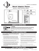
The RBF Series
MODELS:
RBF101 (Supersedes Models RB101 & RB121)
Features & Benefits
■
Retrofits into model RBC wall can or use
with wall can model RBFC
■
Primary and Secondary Thermal Safeguards
•
Robust, heavy duty high temperature
manual power reset
•
Over-temperature one-time thermal fuse
■
Nichrome element wrapped around mica
insulators for durability
■
Powder coat paint process eliminates sharp
cutting edges
■
Stainless steel grill and frame
■
Convenient ON-OFF rocker switch control
■
Two year extended warranty
■
Factory tested and UL listed
WARNING
Turn the electrical power off at the electrical
panel board (circuit breaker or fuse box) and lock
or tag the panel board door to prevent someone
from turning on power while you are working on
the heater. Failure to do so could result in
serious electrical shock, burns, or possible death.
SAVE THESE INSTRUCTIONS
1. Read all instructions before using this heater.
2. Read all information labels. Verify that the electrical supply
wires are the same voltage as the heater.
3. All electrical work and materials must comply with the
National Electric Code (NEC), the Occupational Safety and
Health Act (OSHA), and all state and local codes.
4. Connect the grounding screw provided in the wall can to the
supply ground wire.
5. If you need to install a new circuit or need additional wiring
information, consult a qualified electrician.
6. Protect electrical supply from kinks, sharp objects, oil,
grease, hot surfaces or chemicals.
7. WARNING!
Overheating or fire may occur. DO NOT install the heater in
a floor, ceiling, or behind doors.
8. WARNING!
Fire or explosion may occur. DO NOT install heater in any
area where combustible vapors, gases, liquids, or excessive
lint or dust are present.
9. WARNING!
Burn Hazard. This heater is hot when in use. To avoid burns,
do not let bare skin touch hot surfaces. Use extreme caution
when any heater is used by or near children or invalids.
10. WARNING!
Risk of Electrical Shock. Connect grounding lead to grounding
screw provided. Keep all foreign objects out of heater.
11. WARNING!
Risk of Fire. Do not block heater. Heater must be kept clear of
all obstructions: a minimum of 3 feet in front, 6 inches above
and on both sides. Heater must be kept clean of lint, dirt and
debris. (See Maintenance Instructions).
12. Use this heater only as described in this manual. Any other
use not recommended by the manufacturer may cause fire,
electrical shock, or injury to persons.
IMPORTANT INSTRUCTIONS
O WNER’S GUIDE
www.cadetco.com Tel: 360-693-2505 P.O. Box 1675 Vancouver, WA 98668-1675
TOOLS REQUIRED:
•
Phillips Screwdriver
•
Straight Screwdriver
•
Wire Strippers
•
Utility Knife
•
Insulated Wire Connectors

2
Part Two
Installation Instructions
P
LACEMENT:
UL approved for vertical installation only.
C
ONTROL OF HEATER:
ON-OFF control built into product.
How do I install for new construction?
The wall can is designed to fit between two
standard 16 inches on-center studs. UL requires a
minimum clearance of 6 inches adjacent vertical
surfaces such as walls, shelving, drapes, etc.
M
anufacturer recommends 12 inches from fin-
ished floor and adjacent surfaces. (Note: Front
edge of wall can must be flush with finished wall.
If installing on unfinished wall; face of wall can
must extend from face of stud to allow for thickness
of sheetrock.) Secure the wall can to the studs
with two screws or nails, right or left hand
mounting (See Figure 1).
STEP 1
Mount The Wall Can
How do I install in an existing wall?
Cut a hole 10¼ inches wide by 16¾ inches high
n
ext to wall stud. UL requires a minimum
clearance of 6 inches adjacent vertical surfaces,
such as walls, shelving, drapes, etc. Manufacturer
recommends 12 inches from finished floor and
adjacent surfaces (See Figure 2).
Route supply wire from circuit breaker through
opening in bottom of wall can and secure with
strain relief connector, leaving 6 inches to
10 inches wire lead for later use. Connect
supply ground wire to grounding screw in wall
can (See Figure 1).
STEP 2
Route Supply Wires
Route supply wire from circuit breaker through
opening in bottom of wall can and secure with
strain relief connector, leaving 6 inches to 10
inches wire lead for later use. Connect supply
ground wire to grounding screw in wall can
(See Figure 1).
READ ALL
INSTRUCTIONS
AND SAFETY
INFORMATION
Part One
IMPORTANT!
It is extremely
important you
verify the
electrical supply
wires are the
same voltage as
the heater (i.e. 120
volt heater to 120
volt power supply
and 240 volt heater
to 240 volt power
supply). If
replacing an
existing heater,
check the labels
of the old heater
and replace using
the same voltage.
Hooking a 240 volt
heater to a 120 volt
power supply will
drastically reduce
the heater's
output. Hooking a
120 volt heater to a
240 volt power
supply will
destroy the heater.
Connecting your
heater to an
incompatible
power supply will
void the warranty.
Warranty is void if
any material is
sprayed on the
element or blower.
Use paintmask
provided if walls
are to be textured
or painted.
STEP 3
Mount The Wall Can
STEP 2
Route Supply Wires
STEP 1
Cut Hole In Wall
Figure 2
SCREW
SCREW
S
UPPLY WIRES
GROUND
WIRE
WALL CAN
G
ROUND
SCREW
Figure 1
The wall can is designed to fit between two standard
16 inches on-center studs. Note: Front edge of wall
can must be flush with finished wall (See Figure 2).
Secure the wall can to the studs with two screws
or nails, right or left hand mounting (See Figure 1).
Install spring clips on wall can edge, two at the top
and two at the bottom (See Figure 3). Lay heater
assembly on its front surface and position so rocker
switch will be installed at bottom of wall can
(See Figure 4). Make the connection of the supply
wires to the lead wires from the rocker switch.
Position the heater assembly to fit adapter plate
to the surface of the wall can (See Figure 3).
Be sure all lead wires are inside the wall can before
securing heater assembly. (Use the four #10 32 x ½
inch machine screws; two at top and two at bottom.)
STEP 1
Insert Heater Assembly Into Wall Can
Remove protective film from frame and grill before
installing. Place grill frame outside top and bottom
flanges of the heater assembly. Place grill over
frame and secure with the four finishing washers
and four #10 x 1½ inch Phillips oval head sheet
metal screws (See Figure 3). Start all four screws
before tightening (Note: Over tightening screws
may damage grill).
STEP 2
Install Grill Frame and Grill

Installation Instructions
A. WARNING! Before removing grill, turn the electrical
power off at the electrical panel board (circuit breaker or fuse
box). Lock or tag the panel board door to prevent someone
from accidentally turning the power on while you are working
on the heater. Failure to do so could result in serious electrical
shock, burns, or possible death.
B. It is important that you verify power has been turned off and no
power is going to the heater before proceeding. Circuit breakers
are often not marked correctly and turning the wrong breaker
off could mean electricity is flowing to the heater, even if the
heater does not appear to be working. If you are uncomfortable
working with electrical appliances, unable to follow these
guidelines, or do not have the necessary equipment, consult
a qualified electrician.
C. Once you verify the power has been turned off correctly,
proceed to next step.
D. Remove screws and take off grill.
E. Separate supply wire and lead wire connections.
STEP 1
Remove Existing Heater
Install spring clips on wall can edge, two at the top and two at the
bottom (See Figure 3). Lay heater assembly on its front surface and
position rocker switch to be installed at bottom of wall can
(See Figure 4). Make the connection of the supply wires to the
lead wires from the rocker switch. Position the heater assembly
to fit adapter plate to the surface of the wall can (See Figure 3).
Important: Push wires into bottom of wall can during insertion.
Be sure that wires are not caught between motor and wall can.
Attach assembly using the four #10 32 x ½ inch machine screws;
two at top and two at bottom.
STEP 2
Install Heater Assembly Into Wall Can
Remove protective film from frame and grill before installing.
Place grill frame outside top and bottom flanges of the heater
assembly. Place grill over frame and secure with the four finishing
washers and four #10 x 1½ inch Phillips oval head sheet metal
screws (See Figure 3). Start all four screws before tightening.
(Note: Over tightening screws may damage grill.)
STEP 3
Install Grill Frame and Grill
Figure 3
F
igure 4
3
Retrofitting RBF101 as Replacement for RB Heaters
R
B/RBF
Wall Can
Rocker Switch
Supply
W
ires
For installation in newer RB/RBF wall can only.

WARNING
Risk of Electrical
Shock. Connect
grounding lead to
grounding screw
provided. Keep all
foreign objects out
of heater.
WARNING
Risk of Fire.
Heater must be
kept clear of all
obstructions:
a minimum of
3 feet in front;
6 inches on both
sides and above.
Heater must be
kept clean of lint,
dirt and debris.
WARNING
Turn the electrical
power off at the
electrical panel
board (circuit
breaker or fuse
box) and lock or
tag the panel board
door to prevent
someone from
turning on power
while you are
working on the
heater. Failure
to do so could
result in serious
electrical shock,
burns, or
possible death.
RBF WIRING DIAGRAM
Operation & Maintenance
RESETTING THE MANUAL POWER RESET
LIMIT CONTROL
If the manual power reset limit has opened the
heater circuit due to excessive operating
temperatures, the heater will not work until it is
reset. This can be done at the ON/OFF rocker
switch control or the circuit breaker controlling
the heater.
To reset heater at the ON/OFF
rocker switch control
1. Change rocker switch control to OFF position.
2. Allow the unit to cool for at least 10 minutes.
3. Resolve the problem causing the limit to trip
(typically the heater is blocked or needs
cleaning, see Maintenance Instructions).
4. Change rocker switch control to the ON
position. The heater should come back on.
To reset heater at the circuit breaker
1. Trip the breaker by switching it to the
OFF position.
2. Allow the unit to cool for at least 10 minutes.
3. Resolve the problem causing the limit to trip
(typically the heater is blocked or needs
cleaning, see Maintenance Instructions).
4. Restore power to the heater by switching the
breaker to the ON position.
5. The heater should come back on.
Note that resetting the manual power reset
control may not restore heater operation if
a severe over-temperature condition has
occurred. See the Troubleshooting Guide
below for more information.
How to operate your heater
Once installation is complete and power has been
restored, turn the heater switch on. Important: The
heater will remain on until it is manually turned off.
Maintenance
As needed, or every six months, minimum.
1. WARNING! Before removing grill, turn the
electrical power off at the electrical panel board
(circuit breaker or fuse box). Lock or tag the panel
board door to prevent someone from accidentally
turning the power on while you are working on the
heater. Failure to do so could result in serious
electrical shock, burns, or possible death.
2. It is important that you verify power has been
turned off and no power is going to the heater
before proceeding. Circuit breakers are often not
marked correctly and turning the wrong breaker
off could mean electricity is flowing to the heater,
even if the heater does not appear to be working.
If you are uncomfortable working with electrical
appliances, unable to follow these guidelines,
or do not have the necessary equipment, consult
a qualified electrician.
3. Once you verify the power has been turned off
correctly, proceed to next step.
4. Remove screws and take off grill.
5. Wash grill with hot soapy water and dry immediately.
6. While holding fan (to avoid damage or bending), use
a hair dryer or vacuum on blow cycle to blow debris
through the top element (do not touch element).
7. Vacuum fan area without touching the elements.
8. Replace grill and secure with screws.
9. Turn power back on at the electrical panel board.
About the Heater Temperature-Limiting Controls
The heater is protected by two temperature-limiting
controls. Both controls are integral parts of the
element assembly. The first is a manual power reset
limit control, designed to open the heater circuit when
excessive operating temperatures are detected. The
problem must be assessed and the limit must be reset
to resume operation.
Further protection is provided by a secondary
over-temperature fuse, which will open the heater
circuit in severe over-temperature conditions, or in
the event of component failure. If this occurs, the
heater must be repaired or replaced.
4
Manual Power Reset
High Temperature Limit

Maintenance
For more effective and safer operation and to prolong the life of the
heater, read the Owner’s Guide and follow the maintenance instructions
included with each heater. Failure to properly maintain the heater will
void any warranty and may cause the heater to function improperly.
Warranties are non transferable and apply to original consumer
only. Warranty terms are set out below.
LIMITED TWO-YEAR WARRANTY: Cadet will repair or replace any
RBF Series element or motor found to be defective or malfunctioning
from first date of purchase through the second year.
These warranties do not apply:
1. Damage occurs to the product through improper installation or
incorrect supply voltage;
2. Damage occurs to the product through improper maintenance,
misuse, abuse, accident, or alteration;
3. The product is serviced by anyone other than Cadet;
4. If the date of manufacture of the product cannot be determined;
5. If the product is damaged during shipping through no fault of Cadet.
6. CADET’S WARRANTY IS LIMITED TO REPAIR OR REPLACEMENT AS
SET OUT HEREIN. CADET SHALL NOT BE LIABLE FOR DAMAGES
SUCH AS PROPERTY DAMAGE OR FOR CONSEQUENTIAL
DAMAGES AND/OR INCIDENTAL EXPENSES RESULTING FROM
BREACH OF THESE WRITTEN WARRANTIES OR ANY EXPRESS OR
IMPLIED WARRANTY.
Warranty
C
ONSULT LOCAL ELECTRICAL CODES TO DETERMINE WHAT WORK MUST BE PERFORMED BY QUALIFIED ELECTRICAL SERVICE PERSONNEL.
S
ymptom Problem Solution
B
reaker trips
immediately upon
energizing heater.
Heater fan operates,
but does not discharge
warm air.
Heater discharges
smoke or emits
a burnt odor.
Element heats for
a moment without
the fan turning,
then immediately
stops heating.
Heater does not run.
Troubleshooting Chart
1. Incorrect supply voltage.
2
. Overloaded circuit.
3. A short circuit exists in
the supply or heater wiring.
4. Defective circuit breaker.
1. Insufficient element
temperature.
2. Incorrect supply voltage.
3. Element has failed.
1. Dust, lint or other matter has
accumulated inside heater.
1. Defective motor or
internal connection.
2. Fan or motor jammed.
1. Heater has tripped
the power reset
high-temperature control.
2. Heater has tripped
the secondary
over-temperature fuse.
3. Power not on at the circuit
breaker.
4. Broken or poorly connected
wire(s) to heater.
5. Defective rocker switch
control.
1. Verify that supply voltage matches the heater rating.
2
. The total amperage of all heaters on a branch circuit must not be more than
80% of the amperage rating of the circuit breaker and supply wire ratings.
Reduce the number of heaters on the circuit.
3. Shorted supply or heater wires may be accompanied by severe sparking.
Inspect all supply and heater wiring insulation for damage. Do not reset
the circuit breaker until all electrical shorts have been repaired.
4. Replace the circuit breaker.
1. Allow a few moments for element to reach operating temperature.
2. Verify that supply voltage matches the heater rating.
3. Replace element.
1. Clean heater (See “Operation & Maintenance” section for instructions).
1. Heater or fan motor requires replacement.
2. Remove obstruction and follow instructions in the “Operations &
Maintenance” section for “Resetting the Manual Power Reset Limit
Control.” Test heater operation. If heater does not run, heater requires
repair or replacement.
1. Follow instructions in the “Operation & Maintenance” section for
“Resetting the Manual Power Reset Limit Control.”
2. A severe over-temperature condition has occurred. Repair or replace heater.
3.Turn on the correct circuit breaker in the main panel.
4.Turn off power at circuit breaker. Check supply wire continuity and proper
connection to heater wires.
5.The entire heater, or any of its components may be checked for continuity
to determine the cause of any problems. Repair or replace the heater.
Reduce-Reuse-Recycle
This product is made primarily of recyclable materials.
You can reduce your carbon footprint by recycling this
product at the end of its useful life. Contact your local
recycling support center for further recycling instructions.
©2009 Cadet Manufacturing Co. Printed in U.S.A. Rev. 7/11 #720196
7. IN THE EVENT CADET ELECTS TO REPLACE ANY PART OF YOUR
CADET PRODUCT, THE REPLACEMENT PARTS ARE SUBJECT
TO THE SAME WARRANTIES AS THE PRODUCT. THE INSTALLATION
OF REPLACEMENT PARTS DOES NOT MODIFY OR EXTEND
THE UNDERLYING WARRANTIES. REPLACEMENT OR REPAIR
OF ANY CADET PRODUCT OR PART DOES NOT CREATE ANY
NEW WARRANTIES.
8. These warranties give you specific legal rights, and you may also
have other rights which vary from state to state. Cadet neither
assumes, nor authorizes anyone to assume for it, any other obligation
or liability in connection with its products other than as set out herein.
If you believe your Cadet product is defective, please contact Cadet
Manufacturing Co. at 360-693-2505, during the warranty period, for
instructions on how to have the repair or replacement processed.
Warranty claims made after the warranty period has expired will be
denied. Products returned without authorization will be refused.
Parts and Service
Visit http://support.cadetco.com for information on where to obtain
parts and service.
5
/