
1812-482-2932
Installation
Instructions
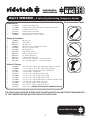
Recommended Tools
www.ridetech.com
Part # 30154700 - 5 Gallon Big Red Analog Compressor System
Components:
2 31920020 Thomas 319 Compressor
1 31194000 RidePro 4 Way analog control panel with rocker switches
1 31915100 5 gallon aluminum tank
1 31937401 Big Red 4 Way valve block
2 90000404 Big Red Valve Mounting Brackets
1 31980005 Pressure switch – 135 On / 150 Off
Wiring & Hardware:
2 31900022 30 amp relay
2 90002924 Fuse holder
2 90001922 20 Amp fuse
2 31900035 Wiring harness - Control panel to valve
6 99104001 10-24 x 1” phillips screw
6 99102002 10-24 Nylok nut
6 99103001 #10 SAE flat washer
3 90001916 #10 x 5/16 ring terminal
2 90001913 12-10 butt connector
2 90001918 Female spade connector
4 99251001 1/4”-20 x 1/2” hex bolts - valve block bracket
4 99253001 1/4” Split Lock Washers - vavle block bracket
Airline & Fittings:
1 31940004 3/8” DOT airline - 30 ft. roll - compressor system, air springs
2 31940000 1/8” DOT airline - 25 ft. roll - valve block to gauges
2 31956102 1/8”npt x 3/8” tube female straight - compressor
2 31957003 2” Brass Nipple - compressor
3 31956201 1/4” npt x 3/8” tube Elbow airline fitting
2 31956000 1/4” npt x 3/8” tube Straight airline fitting
5 31956600 3/8” npt x 3/8” tube Straight airline fitting
4 31952000 1/8” npt x 1/8” tube Straight fitting - manifold to gauge fitting
3 31957004 1/4” npt plug - plug unused tank ports
1 31956004 3/8” npt plug - plug unused supply port
1 31956400 3/8” tube “T” fitting - compressor to tank
1 31959301 Check Valve - SCREWS INTO TANK FOR COMPRESSOR LINE
THE CHECK VALVE SUPPLIED SCREWS INTO THE AIR TANK WITH AN AIR FITTING THREADING INTO
IT. THE COMPRESSOR LINE WILL FEED INTO THE CHECK VALVE.
REV1 5/23/23

2
www.ridetech.com
Installation
Instructions
Part # 30154700 - 5 Gallon RidePro Big Red Compressor System
These are some general guidelines to follow when installing your new RidePro air control system.
Depending on the vehicle there are many different ways to plumb the system. Start out by planning a lay
out of where you want everything to be mounted. Typically we try to keep the compressor, solenoids, tank,
and sending units in a central location, but they can be separated to suit your needs.
Mounting the Compressors/ Pressure Switch
• Remove the negative battery cable before beginning installation.
• All of our compressors are sealed for moisture and dust resistance so they can be mounted anywhere
on the vehicle. Although it is best to mount it in a place out of direct contact with rain and snow. It
is OK to mount it underneath the vehicle but keep it inside the frame rails away from water and debris
thrown off the tire.
• This is a dry compressor; therefore it is maintenance free and can be mounted in any position.
• It is best if mounted to something solid to reduce vibration and noise. If mounting it to sheet metal or
the bed of a truck, use sound deadening material between the compressor and the mounting surface.
• Use the rubber grommets supplied on the feet of the compressor to reduce vibration.
• Apply thread sealant to the pressure switch and screw into the tank.
• One spade of the pressure switch will connect to ground the other to the white wire on the relays.
Mounting the Air Tank
• The air tank can be mounted anywhere on the vehicle in any position.
• If your air system is used frequently you may want to remove the tank once a season to drain any
excessive accumulation of water.
Mounting the Big Red Air Valves
• The valves, like the compressor, are sealed and can be mounted in the same locations. Although if the
vehicle will be exposed to freezing temperatures it is a good idea to mount them in the engine bay if
possible to reduce the possibility of freezing.
• They can be mounted in any position.
• The Big Reds require the mounting brackets to be bolted to the valves. The kits comes with the 1/4”
hardware to attach the brackets to the valves
• Mount the valves higher than the tank to avoid moisture build up. This could cause the air pressure
sensors to give a faulty reading.
• Attach the ground strap to a good, clean ground (preferably the frame).
• The exhaust port will be left open.
• The valve is held closed with the pressure in the tank. If tank pressure drops below air spring pressure
they will equalize deflating all 4 air springs

3812-482-2932
Installation
Instructions
Part # 30154700 - 5 Gallon Big Red Analog Compressor System
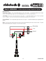
Wiring Harness
Illumination (Gray) - This wire provides power to the switch lights. It should be hooked up to a light
circuit in the vehicle (dash lights) or it can be hooked up to a 12 volt switched source.
+12V (Red) - This wire is the main power for the valves. It should be hooked up to a 12 volt switched
circuit. It needs 12 volt with the key on and should have no power with the key off.
Ground (Black) – This wire provides ground to the switch lights. It should be hooked up to a good ground
source.
Note: The Illumination and Ground wires do not have to be hooked up for the switches to work. They do
have to be hooked up for the lights in the switches to work
Ground
+12V
Illumniation
ILL POWER GROUND
AC BD
RFU
LFU
LFD
RFD

4
www.ridetech.com
Installation
Instructions
Part # 30154700 - 5 Gallon Big Red Analog Compressor System
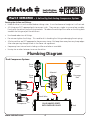
Routing the Airline and Fittings
• Make all airline cuts with a razor blade or tubing cutter. It must be clean and straight or it will not seal.
• All fittings are DOT approved push-to-connect style. They are very simple to use and are reusable.
Firmly push the airline into the fitting to attach. To release the airline pull the collar on the fitting back
towards the fitting and pull the airline out.
• Use thread sealant on all fittings.
• Do not over tighten the fittings. This could result in breaking the fitting or damaging the air spring.
• All of our airlines are DOT approved so they are very strong. But keep them away from any sharp edges.
Also when passing through a hole in the frame use a grommet.
• Keep away from intense heat including mufflers and exhaust manifolds.
• Use zip ties or other fasteners to secure the airline.
Plumbing Diagram
Dual Compressor Systems
RFD LFD
RFU LFU
RRD LRD
RRU LRU
Tank
Compressor
Compressor
Solenoid
Valve
Driver
Front
Driver
Rear
Passenger
Rear
Passenger
Front
Check Valve
PLUG UNUSED PORTS
WITH SUPPLIED PLUGS

5812-482-2932
Installation
Instructions
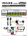
AIR TANK
3/8” AIR LINE
PRESSURE
SWITCH
3/8” TEE
FITTING
LF RF
LR RR
3/8” PLUG IN
SUPPLY PORT
CONTROL PANEL
1/8” AIR LINE
3/8” AIR LINE
3/8” AIR LINE
3/8” FITTING
IN SUPPLY PORT
OF VALVE
VALVE
GROUNDS
CHECK VALVE
3/8” AIR
FITTING
Battery
BLACK
WHITE
RED
GREEN
RED
IGNITION
SWITCH
1/8” NIPPLE 1/8” FEMALE FITTING
FUSE
RELAY
RELAY
1/8” NIPPLE 1/8” FEMALE FITTING
Part # 30154700 - 5 Gallon Big Red Analog Compressor System
Compressor Wiring
• We provided a wire chart below to help select the correct size wire for your install. The air compressorS
in this kit draw 19.6 amps max EACH.
• Use the diagram below for wiring the compressor, relay, and pressure switch.
Wiring & Plumbing Diagram
0‐4ft 4‐7ft 7‐10ft 10‐13ft 13‐16ft 16‐19ft 19‐22ft
15‐20 12ga 12ga 12ga 12ga10ga 8ga 8ga
20‐35 12ga 10ga 10ga 10ga 10ga 8ga 8ga
35‐50 10ga 10ga 10ga 8ga 8ga 8ga 6or4ga
Amps@
13.8Volts
LENGTHOFWIRE
AmericanWireGauge(AWG)

6
www.ridetech.com
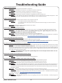
Troubleshooting Guide
Compressor will not turn on.
Diagnosis A: 12 volts not present at Red wire on compressor.
Solution A: Check fuse and connections. (20 amp fuse on Thomas compressor)
Diagnosis B: 12 volts present at red wire on compressor but still doesn’t run.
Solution B: Check connections between Black wire on compressor and ground.
Diagnosis C: 12 volts present at red wire on compressor and good ground, but still doesn’t run.
Solution C: The compressor has gotten hot and thermals out. The air compressors have a thermal safety built in. If the
compressor gets too hot, it will shut itself o. Let the compressor cool, it should come back on,
Compressor will not turn o.
Diagnosis A: Unhook wire at pressure switch to see if compressor shuts o.
Solution A: 1. If compressor doesn’t shut o - Replace relay.
2. If compressor shuts o and you know the system has more than enough air in the tank - Replace
pressure switch.
Diagnosis B: Tank pressure builds normally but will not reach 150psi.
Solution B: Replace compressor.
One air spring leaks down over a period of time.
Diagnosis A: Leak between delivery port on valve block and air spring. ALL FITTINGS NEED SOME KIND OF THREAD SEALER.
Solution A: Air springs almost never leak. Spray all ttings with soapy water. Tighten tting and/or remove and
replace thread sealant. Cut 1” o of end of airline and reinsert.
Diagnosis B: Exhaust valves leaking. Air seeps past exhaust valve and out exhaust port.
Solution B: Usually caused by debris stuck on valve seat. Inate and deate several times or disassemble valve. Information
about servicing the valves can be found at: https://www.ridetech.com/tech/solenoid-valve-service/
One air spring leaks up over a period of time.
Diagnosis A: Inate valves leaking. Air seeps past inate valve and into air spring.
Solution A: Usually caused by debris stuck on valve seat. Inate and deate several times or disassemble valve. Information
about servicing the valves can be found at: https://www.ridetech.com/tech/solenoid-valve-service/
The 2 front or all 4 air springs leak down over a period of time.
Diagnosis A: Check tank pressure. There is a leak in the supply side of the system. This could be at the compressor, tank, or supply
ports on the valve. The valves are held closed by the tank pressure. If the tank pressure gets below the air spring pressure, the
air spring will leak down with the tank. An easy way to check this; make sure the compressor runs until it shuts o. Write down the
tank pressure and let the vehicle sit over night. If the compressor kicks on right away the next time you turn on the system, you
have a leak on the supply side of the system.
Solution A: Spray all ttings with soapy water. Tighten tting and/or remove and replace thread sealant. Cut 1” o
of end of airline and reinsert.
Control panel switches do not activate the correct air spring.
Diagnosis : Ex: LF switch actuates the RF air spring.
Solution : Swap the switch harness on the back of the gauge panel.
One corner will not inate or deate, but the others inate and deate.
Diagnosis A: With the vehicle running, check to see if the valve clicks when the button is pushed.
Solution A: If no click, check the harness going to valves and the grounds at the valve block.
Diagnosis B: With the vehicle running, check to see if the valve clicks when the button is pushed.
Solution B: If no click, check the grounds at the valve block. You can also test the wire of the coil of the solenoid that isn’t
working. Each coil of the valve block has 2 wires. One wire is ground, the other wire is the control wire. You should see 12
volts on this wire when the button for the solenoid is pushed. Use a volt meter on this wire to see if you have 12 volts when
the button is pushed.
Diagnosis C: With the vehicle running, check to see if the valve clicks when the button is pushed.
Solution C: If valve clicks, but does not open. The plunger in the valve is can be badly dimpled and needs replaced. If the
plunger is badly dimpled, it can get stuck in the hole in the valve, not allowing it to open. Information about servicing the
valves can be found at: https://www.ridetech.com/tech/solenoid-valve-service/
Diagnosis D: System is getting LOW voltage.
Solution D: Start the vehicle and test to see if you are getting at least 12.5 volts at the battery. A battery charger isn’t
enough to run the system.

7812-482-2932
Tips & Tricks
When inating and deating the vehicle manually, push both buttons for one end of the vehicle at the same time.
Explanation: When you do one corner at a time, it is harder to get the vehicle level at the height you are trying to achieve. By
pushing both inate buttons at the same time, each side of the vehicle works together to lift the vehicle. When you get close to
the height you are trying to obtain, then you can adjust the air in each corner individually.
Pressure dierential from side to side.
Explanation: It is not uncommon for a vehicle to have more pressure in one side. Several things can aect the air pressure
from side to side; weight distribution and chassis twist are the two most common causes. Airing up both front or both rear at the
same time will help get the vehicle closer to level than trying to do it one corner at a time. A 10-15 psi dierential from one side
to the other is not uncommon.
Tip: After you have leveled the vehicle, take a look at all 4 pressures. If two corners opposite of each other are your higher
pressures, you may be cross loading the vehicle. Example: The Left Front has a higher pressure than Right Front and Right
Rear has a higher pressure the Left Rear, there’s a good chance the 2 higher pressure air springs are pushing against each other.
Try getting the pressures closer to the opposite side of the vehicle on each end and see how the vehicle sits.
Swapping airlines to help diagnose a problem.
Explanation: Air lines can be swapped from one port to the another to help diagnose a problem. This can help you narrow down
where a problem may be.
Example: Right rear will not air up, but left rear will - switch the right rear and left rear air lines. The operation of the rear will
now be switched at the control panel, but the air pressures will still be correct for the corners. If the right rear will still not air
up using the left rear button, your problem is somewhere from the right rear valve to air spring. If the right rear will now air
up using the left rear button, the problem is in the wiring controlling the valve.
When checking for air leaks, DO NOT USE DISH SOAP!
Explanation: Today’s dish soaps are designed to shed water o of dishes. This causes the soap and water mixture to run o the
airline. It can run o the airline before it has a chance to bubble.
Tip: The bubble mixture that kids use to blow bubbles is a great leak detector. Windex also works well for checking for leaks.
SUSPENSION BIND
Ever noticed that when you lower any vehicle o of a lift or jack stands that it is sitting several inches higher than normal? This
condition is due to Suspension Bind, and all vehicles have it. Three dynamics lead to suspension bind:
TECH TIP
1. Tire Scrub - The arc created by the control arm swing will try to push your tires apart or pull them together, (basically)
changing the track width). However, friction between the tire and ground does not allow the tires to slide, reducing vehicle
movement. This can be especially dramatic with sticky tires and concrete.
2. Control Arm Bushing – Friction between the bushing and the frame brackets will also reduce vehicle movement. This is why
control arm bolts must be tightened at ride height. Over-tightening the bolts can lead to very excessive suspension bind.
3. Shock Absorbers – The shock absorber’s job is to reduce suspension movement. The stier the shock absorber, the more
suspension bind.
With an air suspension vehicle, it is always best to over inate the air spring and then deate back down to the target pressure
to alleviate some suspension bind.
-
 1
1
-
 2
2
-
 3
3
-
 4
4
-
 5
5
-
 6
6
-
 7
7


Ask a question and I''ll find the answer in the document
Finding information in a document is now easier with AI
Related papers
-
Ridetech 30534700 Installation guide
-
-
-
-
-
Ride Tech HQ Air Suspension System Operating instructions
-
-
-
-
Other documents
-
 TPC TIREBOSS User manual
-
Vixen Horns VXO8334BI Train Horn Kit for Trucks/Cars Installation guide
-
 Firestone Add Air User manual
-
 Firestone 4-corner User manual
-
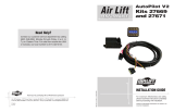 Air Lift Performance 27669 Installation guide
-
ARB CKMA24 Installation guide
-
-
-
Graco 308611ZAB RoadLazer Line Striper System Operating instructions
-


