Page is loading ...

1
80-1101-01
Rev. 05.3
INSTRUCTION MANUALINSTRUCTION MANUAL
INSTRUCTION MANUALINSTRUCTION MANUAL
INSTRUCTION MANUAL

2
INTRODUCTION TO THE MANUAL
This manual contains the information needed
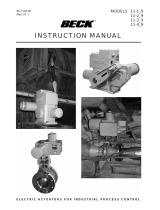
to install, operate and maintain the Beck 11-160,
11-260, 11-360 and 11-460 Electronic Control
Drives, manufactured by Harold Beck & Sons, Inc.
of Newtown, Pennsylvania.
The Group 11 drive is a powerful control pack-
age designed to provide modulating control of quar-
ter-turn valves requiring up to 1,800 lb-ft of drive
torque.
NOTICE: This manual contains information thatNOTICE: This manual contains information that
NOTICE: This manual contains information thatNOTICE: This manual contains information that
NOTICE: This manual contains information that
will make installation simple, efficient andwill make installation simple, efficient and
will make installation simple, efficient andwill make installation simple, efficient and
will make installation simple, efficient and
trouble-free. Please read and understand thetrouble-free. Please read and understand the
trouble-free. Please read and understand thetrouble-free. Please read and understand the
trouble-free. Please read and understand the
appropriate sections in this manual before at-appropriate sections in this manual before at-
appropriate sections in this manual before at-appropriate sections in this manual before at-
appropriate sections in this manual before at-
tempting to install or operate your drive.tempting to install or operate your drive.
tempting to install or operate your drive.tempting to install or operate your drive.
tempting to install or operate your drive.
Group 11 quarter-turn drives and valve/drive
assemblies provide precise, reliable control of ball,
plug and butterfly valves. All drives are delivered
fully calibrated to the specifications written into the
equipment order and are ready for installation.
Group 11 rotary drives ...Group 11 rotary drives ...
Group 11 rotary drives ...Group 11 rotary drives ...
Group 11 rotary drives ...
provide precise position control of dampers,
valves, fluid couplings, and other devices re-
quiring up to 1,800 lb-ft drive torque.
Group 14 linear drives ...Group 14 linear drives ...
Group 14 linear drives ...Group 14 linear drives ...
Group 14 linear drives ...
are ideally suited for globe
valves from 1” to 8” diam-
eter. Beck’s unique
“Tight-Seater™” coupling
provides positive seating
of valves.
Group 31 rotary drives ...Group 31 rotary drives ...
Group 31 rotary drives ...Group 31 rotary drives ...
Group 31 rotary drives ...
are particularly suited for
coupling to ball, plug, and
butterfly valves up to 4” di-
ameter, and small damp-
ers.

3
CONTENTS
PRODUCT SUMMARYPRODUCT SUMMARY
PRODUCT SUMMARYPRODUCT SUMMARY
PRODUCT SUMMARY
Beck control drives are engineered for precise,
reliable operation of quarter-turn valves. The cool,
stable operation of Beck’s control motors coupled
with the powerful gear train provide the tight, re-
sponsive control required by modern control loops
to optimize output while keeping operating costs
low.
The unique, all spur gear construction used in
the Beck control drive is designed for long term
durability. The gear train can withstand accidental
stalls of up to four days without failure, and will
resume instant response immediately upon re-
moval of the condition (see page 22 for Stall Pro-
tection and Annunciation information). Gear
modules and motors can be interchanged in the
field to alter the torque and timing as needed if the
application requirements change. Mechanical
stops in the gear train prevent over-travel.
An easy-to-turn, spoke-free Handwheel is in-
corporated into the design to allow manual opera-
tion during installation or power outages. The
Handwheel can be used to move valves to any
position smoothly and easily under full load condi-
tions.
Valves may also be operated at their individual
locations with built-in electric Handswitches.
Beck’s ESR-4 Electronic Signal Receiver pro-
vides precise drive control from either conventional
analog or computer based control systems.
Beck’s CPS-2 Contactless Position Sensor pro-
vides accurate position feedback in demanding
environmental conditions, with no contacting or
wiping surfaces to wear or intermittently lose con-
tact. The CPS-2 provides infinite resolution with
linearity error of less than ±1% of span over full
control drive travel.
Beck electronic control drives are designed with
individual weatherproof enclosures to protect the
main components.
TYPICAL APPLICATIONSTYPICAL APPLICATIONS
TYPICAL APPLICATIONSTYPICAL APPLICATIONS
TYPICAL APPLICATIONS
Group 11 units are engineered for direct cou-
pling on quarter-turn ball, plug, and butterfly valves.
Drives can be supplied assembled to valves for
in-line installation or with hardware for mounting to
existing valves.
Used in thousands of modulating valve appli-
cations, Beck drives have a field-proven track
record for 100% availability and tight, reliable clo-
sure.
Product DescriptionProduct Description
Product DescriptionProduct Description
Product Description....................................................................................................................................................... 4
General Specifications ............................................................................................................................................... 4
Outline Drawings ....................................................................................................................................................... 6
InstallationInstallation
InstallationInstallation
Installation .................................................................................................................................................................... 11
Input Signal Wiring .................................................................................................................................................. 12
Feedback Signal Wiring ........................................................................................................................................... 14
Wiring Options ......................................................................................................................................................... 16
Start-up .................................................................................................................................................................... 19
OperationOperation
OperationOperation
Operation ...................................................................................................................................................................... 20
CalibrationCalibration
CalibrationCalibration
Calibration
Switches .................................................................................................................................................................. 24
Direction Change ..................................................................................................................................................... 26
Feedback Signal ...................................................................................................................................................... 28
Input Signal .............................................................................................................................................................. 32
MaintenanceMaintenance
MaintenanceMaintenance
Maintenance
Routine .................................................................................................................................................................... 36
Component Replacement ........................................................................................................................................ 37
Troubleshooting ....................................................................................................................................................... 41
AppendixAppendix
AppendixAppendix
Appendix
Spare Parts .............................................................................................................................................................. 45
Components ............................................................................................................................................................ 46
CPS-2 Functional Block Diagrams .......................................................................................................................... 50
CPS-2 Data .............................................................................................................................................................. 51
IndexIndex
IndexIndex
Index.............................................................................................................................................................................. 54
ServicesServices
ServicesServices
Services ........................................................................................................................................................................ 55

4
PRODUCT DESCRIPTION
GENERAL SPECIFICATIONS—ALL MODELSGENERAL SPECIFICATIONS—ALL MODELS
GENERAL SPECIFICATIONS—ALL MODELSGENERAL SPECIFICATIONS—ALL MODELS
GENERAL SPECIFICATIONS—ALL MODELS
Input Power 120 V ac single-phase 50 or 60 Hz Allowable Tolerance +10%
240 V ac single-phase 50 or 60 Hz -15%
Max. Current and Power
Model 120 V ac 240 V ac
11-160 .40 A 48 W .20 A 48 W
11-260 .65 A 78 W .33 A 78 W
11-360 .65 A 78 W .33 A 78 W
11-460 3.10 A 400 W 1.55 A 400 W
Operating Conditions -40° to 85°C (-40° to 185°F)
0 to 99% relative humidity
Input Signal Options, with 0–5 mA
Electronic Signal Receiver 1–5 mA
(ESR-4) 4–20 mA
10–50 mA
1–5 V dc
-10 to 10 V dc
Input Signal Span Adj. 50% to 400% of span (except -10 to 10 V dc)
Input Signal Zero Adj. -100% to +275% of span (except -10 to 10 V dc)
Deadband 0.6% of span
Sensitivity 25% of deadband
Direct AC Control 120 V ac for 2-position, multi-position or modulating V ac control
Square Function (Optional) Drive output shaft moves proportionally to the square of the input signal.
Feedback Signal Options, with 1–5 mA
Contactless Position Sensor 4–20 mA
(CPS-2) 10–50 mA
1–5 V dc
0–16 V dc
-10 to +10 V dc
Output Stability 0.25% of span from 102 to 132 V ac
±0.03% of span/°C for 0 to 50°C, ±0.05% of span/°C for -40° to 85°C
Linearity ±1% of span, max. independent error
Hysteresis 0.25% of span at any point
Isolation Max. leakage of 10 µA at 60 V rms, 60 Hz from output to ground

5
GENERAL SPECIFICATIONS—ALL MODELS (cont’d)GENERAL SPECIFICATIONS—ALL MODELS (cont’d)
GENERAL SPECIFICATIONS—ALL MODELS (cont’d)GENERAL SPECIFICATIONS—ALL MODELS (cont’d)
GENERAL SPECIFICATIONS—ALL MODELS (cont’d)
Film Potentiometer 1,000 ohms
Max. Voltage 40 V
Wattage 2 W max.
Linearity ±0.5%
Max. Wiper Current 1 mA
Action on Loss of Power Stays in place
Action on Loss of Input Stays in place or moves to full travel or zero position. Drives to any
Signal (Power On) preset position with optional switch assembly on Models 11-__7 and
11-__8. Field adjustable.
Stall Protection and If the motor tries to run in one direction for more than 300 seconds, the
Annunciation Stall Protection Module will shut off power to the motor and a solid
(Optional) state relay will change state. The relay is rated for 120 V ac or dc,
10 VA.
Limit Switches Two SPDT, one for CW and one for CCW extended limit of travel.
Standard switch setting is for 90° of travel.
Auxiliary Switches Up to four 6 A, 120 V ac switches available.
Switches are labeled S1 to S4 and are cam-operated, field-adjustable.
S1 and S4 are set to operate just before reaching the CCW travel limit.
S2 and S3 are set to operate just before reaching the CW travel limit.
Handswitch Permits local electrical operation, independent of controller signal.
Standard on all units.
Handwheel Provides manual operation without electrical power.
Motor 120 V ac, single-phase, no-burnout, non-coasting motor has instant
magnetic braking. Requires no contacts or moving parts. Can remain
stalled for approximately 4 days (cumulative) without damaging the
gear train.
Gear Train High-efficiency, precision-cut, heat-treated alloy steel and ductile iron
spur gears. Interchangeable gear modules permit field change of
timing.
Mechanical Stops Prevent overtravel during automatic or manual operation.
Enclosure Precision-machined aluminum alloy castings, painted with corrosion-
resistant polyurethane paint, provide a rugged, dust-tight, weatherproof
enclosure.

6
PRODUCT DESCRIPTION
MODEL 11-160 SPECIFICATIONSMODEL 11-160 SPECIFICATIONS
MODEL 11-160 SPECIFICATIONSMODEL 11-160 SPECIFICATIONS
MODEL 11-160 SPECIFICATIONS
(All Dimensions in Inches)(All Dimensions in Inches)
(All Dimensions in Inches)(All Dimensions in Inches)
(All Dimensions in Inches)
Recommended Bolt TorquesRecommended Bolt Torques
Recommended Bolt TorquesRecommended Bolt Torques
Recommended Bolt Torques
NOTE: All dimensions subject to change.
BASIC CONTROL DRIVEBASIC CONTROL DRIVE
BASIC CONTROL DRIVEBASIC CONTROL DRIVE
BASIC CONTROL DRIVE
TYPICAL VALVE MOUNTINGTYPICAL VALVE MOUNTING
TYPICAL VALVE MOUNTINGTYPICAL VALVE MOUNTING
TYPICAL VALVE MOUNTING

7
MODEL 11-260 SPECIFICATIONSMODEL 11-260 SPECIFICATIONS
MODEL 11-260 SPECIFICATIONSMODEL 11-260 SPECIFICATIONS
MODEL 11-260 SPECIFICATIONS
(All Dimensions in Inches)(All Dimensions in Inches)
(All Dimensions in Inches)(All Dimensions in Inches)
(All Dimensions in Inches)
Recommended Bolt TorquesRecommended Bolt Torques
Recommended Bolt TorquesRecommended Bolt Torques
Recommended Bolt Torques
NOTE: All dimensions subject to change.
TYPICAL VALVE MOUNTINGTYPICAL VALVE MOUNTING
TYPICAL VALVE MOUNTINGTYPICAL VALVE MOUNTING
TYPICAL VALVE MOUNTING
BASIC CONTROL DRIVEBASIC CONTROL DRIVE
BASIC CONTROL DRIVEBASIC CONTROL DRIVE
BASIC CONTROL DRIVE

8
PRODUCT DESCRIPTION
MODEL 11-360 SPECIFICATIONSMODEL 11-360 SPECIFICATIONS
MODEL 11-360 SPECIFICATIONSMODEL 11-360 SPECIFICATIONS
MODEL 11-360 SPECIFICATIONS
(All Dimensions in Inches)(All Dimensions in Inches)
(All Dimensions in Inches)(All Dimensions in Inches)
(All Dimensions in Inches)
Recommended Bolt TorquesRecommended Bolt Torques
Recommended Bolt TorquesRecommended Bolt Torques
Recommended Bolt Torques
NOTE: All dimensions subject to change.
TYPICAL VALVE MOUNTINGTYPICAL VALVE MOUNTING
TYPICAL VALVE MOUNTINGTYPICAL VALVE MOUNTING
TYPICAL VALVE MOUNTING
BASIC CONTROL DRIVEBASIC CONTROL DRIVE
BASIC CONTROL DRIVEBASIC CONTROL DRIVE
BASIC CONTROL DRIVE

9
MODEL 11-460 SPECIFICATIONSMODEL 11-460 SPECIFICATIONS
MODEL 11-460 SPECIFICATIONSMODEL 11-460 SPECIFICATIONS
MODEL 11-460 SPECIFICATIONS
(All Dimensions in Inches)(All Dimensions in Inches)
(All Dimensions in Inches)(All Dimensions in Inches)
(All Dimensions in Inches)
Recommended Bolt TorquesRecommended Bolt Torques
Recommended Bolt TorquesRecommended Bolt Torques
Recommended Bolt Torques
NOTE: All dimensions subject to change.
BASIC CONTROL DRIVEBASIC CONTROL DRIVE
BASIC CONTROL DRIVEBASIC CONTROL DRIVE
BASIC CONTROL DRIVE TYPICAL VALVE MOUNTINGTYPICAL VALVE MOUNTING
TYPICAL VALVE MOUNTINGTYPICAL VALVE MOUNTING
TYPICAL VALVE MOUNTING

10
TABLE 1:TABLE 1:
TABLE 1:TABLE 1:
TABLE 1:
SUMMARY OF CONTROL OPTIONSSUMMARY OF CONTROL OPTIONS
SUMMARY OF CONTROL OPTIONSSUMMARY OF CONTROL OPTIONS
SUMMARY OF CONTROL OPTIONS
*13-2245-09 Square Function Board is available in these ranges.
PRODUCT DESCRIPTION

11
INSTALLATION
SAFETY PRECAUTIONSSAFETY PRECAUTIONS
SAFETY PRECAUTIONSSAFETY PRECAUTIONS
SAFETY PRECAUTIONS
WARNINGWARNING
WARNINGWARNING
WARNING
Installation and service instructions are for useInstallation and service instructions are for use
Installation and service instructions are for useInstallation and service instructions are for use
Installation and service instructions are for use
by qualified personnel only. To avoid injuryby qualified personnel only. To avoid injury
by qualified personnel only. To avoid injuryby qualified personnel only. To avoid injury
by qualified personnel only. To avoid injury
and electric shock, do not perform any servic-and electric shock, do not perform any servic-
and electric shock, do not perform any servic-and electric shock, do not perform any servic-
and electric shock, do not perform any servic-
ing other than that contained in this manual.ing other than that contained in this manual.
ing other than that contained in this manual.ing other than that contained in this manual.
ing other than that contained in this manual.
STORAGE INFORMATIONSTORAGE INFORMATION
STORAGE INFORMATIONSTORAGE INFORMATION
STORAGE INFORMATION
The drive should be stored in its shipping car-
ton in a clean, dry area.
If it is necessary to store the drive outdoors for
a long period of time, it should be removed from its
shipping carton and stored above ground. A wa-
terproof cover should be securely fastened over it.
Do not stack drives on top of one another. Stored
drives should be periodically checked to make sure
no condensation has formed in the control com-
partments. Damage due to moisture while in stor-
age is not covered by warranty.
UNPACKINGUNPACKING
UNPACKINGUNPACKING
UNPACKING
Beck drives are packed in standardized card-
board shipping containers. Drives mounted on
valves are strapped to a skid and crated. After
unpacking, the wooden platform may be used to
transport the drive to the installation site.
INSTALLATION—ELECTRICALINSTALLATION—ELECTRICAL
INSTALLATION—ELECTRICALINSTALLATION—ELECTRICAL
INSTALLATION—ELECTRICAL
NOTE: All Beck drives are shipped from theNOTE: All Beck drives are shipped from the
NOTE: All Beck drives are shipped from theNOTE: All Beck drives are shipped from the
NOTE: All Beck drives are shipped from the
factory ready for installation; no electrical ad-factory ready for installation; no electrical ad-
factory ready for installation; no electrical ad-factory ready for installation; no electrical ad-
factory ready for installation; no electrical ad-
justments are required before placing them injustments are required before placing them in
justments are required before placing them injustments are required before placing them in
justments are required before placing them in
operation. Each drive is set up and calibratedoperation. Each drive is set up and calibrated
operation. Each drive is set up and calibratedoperation. Each drive is set up and calibrated
operation. Each drive is set up and calibrated
to the customer’s specifications that were writ-to the customer’s specifications that were writ-
to the customer’s specifications that were writ-to the customer’s specifications that were writ-
to the customer’s specifications that were writ-
ten into the equipment order.ten into the equipment order.
ten into the equipment order.ten into the equipment order.
ten into the equipment order.
Two N.P.T. conduit connections are provided
for power and signal wiring to the drive. The 1/2"
conduit is provided for signal wiring connections,
and the 1" conduit is provided for power and auxil-
iary switch connections. A sealant must be used
on threaded conduit connections to keep moisture
out. Conduits should be routed from below the
drive so that condensation and other contaminants
entering the conduit cannot enter the drive.
A large, clearly labeled terminal block on the
top of the drive is enclosed in a separate, gasketed
metal enclosure. Terminals will accommodate up
to 12 AWG wiring (see pages 6–9 for location of
the terminal block).
CAUTIONCAUTION
CAUTIONCAUTION
CAUTION
Always close covers immediately after instal-Always close covers immediately after instal-
Always close covers immediately after instal-Always close covers immediately after instal-
Always close covers immediately after instal-
lation or service to prevent moisture or otherlation or service to prevent moisture or other
lation or service to prevent moisture or otherlation or service to prevent moisture or other
lation or service to prevent moisture or other
foreign matter from entering the drive.foreign matter from entering the drive.
foreign matter from entering the drive.foreign matter from entering the drive.
foreign matter from entering the drive.
Refer to the wiring diagram furnished with your
Beck drive for proper AC power and signal con-
nections. It is advisable to provide normal short
circuit protection on the AC power line. A copy of
the wiring diagram is shipped with each drive and
is fastened to the inside of the terminal block cover.
If there is no wiring diagram available, you may
obtain a copy from Beck by providing the serial
number of your drive.
Your Beck drive has been supplied to match
the signal source in your control loop. If it does not
match, refer to the Input Signal Options section of
this manual, page 16, for information on how to
change the input signal range.
For maximum safety, the Beck drive body
should be grounded. Use the grounding terminal
in the wiring compartment of the drive.

12
INSTALLATION
Option 8, ModulatingOption 8, Modulating
Option 8, ModulatingOption 8, Modulating
Option 8, Modulating
Analog Position Control with
Contactless Position Sensing
Customer must supply two wires to power the
drive: One 120 V ac line (terminal C), and one
neutral (terminal B). Customer must supply two
wires for the modulating analog control signal:
Connect to terminal AA (+) and to terminal BB(-).
Customer may supply two additional wires to
monitor the analog position feedback signal (see
pages 14 and 15 for connections). The drive’s
feedback circuit power supply is derived from the
120 V ac line, therefore the feedback signal must
be wired to a “4-wire” type non-powered analog
input.
Option 7, ModulatingOption 7, Modulating
Option 7, ModulatingOption 7, Modulating
Option 7, Modulating
Analog Position Control with
Potentiometer Position Sensing
Customer must supply two wires to power the
drive: One 120 V ac line (terminal C), and one
neutral (terminal B). Customer must supply two
wires for the modulating analog control signal:
Connect to terminal AA (+) and to terminal BB (-).
If position feedback monitoring is required, an op-
tional auxiliary potentiometer can be ordered.
The optional auxiliary potentiometer connects to
terminals CC (Reverse), DD (Wiper), and EE
(Forward) and is compatible with standard
“slidewire” style inputs.
Each Beck drive is custom built with one of six
separate control configurations which are pro-
vided to match the control requirements of your
system. Basic wiring connections for each con-
trol option are described in the following
paragraphs and diagrams.
The wiring diagram specific to each drive is at-
tached to the inside of the wiring terminal cover.
See Table 1, page 10, for model numbers and
control selections.
Feedback connections for drives incorporat-
ing the Contactless Position Sensor (CPS-2) for
control options 6 and 8 are described on pages
14–15.
A drive can be ordered with up to four optional
auxiliary switches. Wiring connections for these
are described on page 24.
To disable the Handswitch, remove the
jumper between terminals A and C, and add
jumpers between terminals N and V, M and U.

13
Option 6, ModulatingOption 6, Modulating
Option 6, ModulatingOption 6, Modulating
Option 6, Modulating
Direct AC Control with Contactless
Position Sensing
Customer must supply three wires to directly
control the drive motor direction: One 120 V ac
line to run Forward (terminal M), one 120 V ac line
to run Reverse (terminal N), and one neutral (ter-
minal B). Customer may supply two additional
wires to monitor the analog position feedback sig-
nal (see pages 14 and 15 for connections). If
position feedback monitoring is desired, a 120 V
ac line must be connected to terminal C. The
drive’s feedback circuit power supply is derived
from this 120 V ac line, therefore the feedback
signal must be wired to a “4-wire” type,
non-powered analog input.
Option 5, ModulatingOption 5, Modulating
Option 5, ModulatingOption 5, Modulating
Option 5, Modulating
Direct AC Control with Potentiometer
Position Sensing
Customer must supply three wires to directly
control the drive motor direction: One 120 V ac
line to run Forward (terminal M), one 120 V ac line
to run Reverse (terminal N), and one neutral (ter-
minal B). The position feedback potentiometer
connections are available at terminals CC (Re-
verse), DD (Wiper), and EE (Forward).
Option 4, Multi-PositionOption 4, Multi-Position
Option 4, Multi-PositionOption 4, Multi-Position
Option 4, Multi-Position
Direct AC Control with Cam-Operated
Switches to Stop Drive Travel
Customer must supply three wires to directly
control the drive motor direction: One 120 V ac
line to run Forward (terminal M), one 120 V ac line
to run Reverse (terminal N), and one neutral (ter-
minal B). Up to six intermediate stop positions
may be specified, each requiring an additional
120 V ac line.
Option 3, Open / CloseOption 3, Open / Close
Option 3, Open / CloseOption 3, Open / Close
Option 3, Open / Close
Direct AC Control
Customer must supply three wires to directly
control the drive motor direction: One 120 V ac
line to run Forward (terminal M), one 120 V ac line
to run Reverse (terminal N), and one neutral (ter-
minal B).
240 V ac Operation240 V ac Operation
240 V ac Operation240 V ac Operation
240 V ac Operation
All of the options described above are avail-
able for 240 V ac operation instead of 120 V ac
operation. In all cases, the power neutral is re-
placed with Line 2 of the 240 V ac, and the 120 V
ac line is replaced with Line 1 of the 240 V ac.

14
INSTALLATION
CPS-2 SIGNAL CONNECTIONSCPS-2 SIGNAL CONNECTIONS
CPS-2 SIGNAL CONNECTIONSCPS-2 SIGNAL CONNECTIONS
CPS-2 SIGNAL CONNECTIONS
Beck drives equipped with the Contactless
Position Sensor (CPS-2) are shipped ready for in-
stallation to match the proper mA or V dc feed-
back range in your system.
Customer connections for feedback signal wir-
ing on each CPS-2 model are described in the fol-
lowing diagrams and paragraphs. Refer to Table
13, page 51, for information on output signal
ranges, output terminals, range-changing resis-
tance values, and terminals to which the ranging
resistor or jumper is connected.
NOTE: For output shaft rotation of less thanNOTE: For output shaft rotation of less than
NOTE: For output shaft rotation of less thanNOTE: For output shaft rotation of less than
NOTE: For output shaft rotation of less than
8080
8080
80°, refer to Calibration Procedure, page 28., refer to Calibration Procedure, page 28.
, refer to Calibration Procedure, page 28., refer to Calibration Procedure, page 28.
, refer to Calibration Procedure, page 28.
To verify that the feedback signal range is cor-
rect for your drive, see the instructions of page 29.
NOTE: Ranging resistors must be connectedNOTE: Ranging resistors must be connected
NOTE: Ranging resistors must be connectedNOTE: Ranging resistors must be connected
NOTE: Ranging resistors must be connected
to the control drive output terminals. If rang-to the control drive output terminals. If rang-
to the control drive output terminals. If rang-to the control drive output terminals. If rang-
to the control drive output terminals. If rang-
ing resistor change is required, use a resistoring resistor change is required, use a resistor
ing resistor change is required, use a resistoring resistor change is required, use a resistor
ing resistor change is required, use a resistor
with with
with with
with ±1% tolerance. Resistors can be ordered1% tolerance. Resistors can be ordered
1% tolerance. Resistors can be ordered1% tolerance. Resistors can be ordered
1% tolerance. Resistors can be ordered
from Beck.from Beck.
from Beck.from Beck.
from Beck.
CPS-2 Model 20-3400-02, -12CPS-2 Model 20-3400-02, -12
CPS-2 Model 20-3400-02, -12CPS-2 Model 20-3400-02, -12
CPS-2 Model 20-3400-02, -12
Terminal ConnectionsTerminal Connections
Terminal ConnectionsTerminal Connections
Terminal Connections
1. A single 4–20 mA current output is available
between terminals EE (+) and CC (-) when
driving into an external load between 250 and
800 ohms. No ranging resistor is required.
2. For 4–20 mA and / or 1–5 V dc output, 4–20
mA is available across EE (+) and DD (-); 500
ohms is the maximum external load (for larger
loads see Item 1 above). A 1–5 V dc signal is
available across DD (+) and CC (-) into a 12 K
ohm resistive load when the circuit between
EE and DD is completed.
CPS-2 Model 20-3400-03, -13CPS-2 Model 20-3400-03, -13
CPS-2 Model 20-3400-03, -13CPS-2 Model 20-3400-03, -13
CPS-2 Model 20-3400-03, -13
Current FeedbackCurrent Feedback
Current FeedbackCurrent Feedback
Current Feedback
Terminal ConnectionsTerminal Connections
Terminal ConnectionsTerminal Connections
Terminal Connections
The universal model has current sensing ter-
minals, which allow for various current signal
ranges. Current output is available between ter-
minals DD (+) and CC (-) with the proper ranging
resistor connected across terminals DD and EE.
Units are factory-calibrated for specified sig-
nal ranges and are provided with proper resistors
installed.
The ranging resistor value is given in Table
13, page 51, or can be calculated using the fol-
lowing equation:
4-20 mA Signal Output4-20 mA Signal Output
4-20 mA Signal Output4-20 mA Signal Output
4-20 mA Signal Output
Dual Signal OutputDual Signal Output
Dual Signal OutputDual Signal Output
Dual Signal Output
Where R = Resistor (Ohms) Connected from
DD to EE
I = Output Current Span (Amp)
If converting to a zero-based range (a range
that includes zero as an end point), refer to “Ad-
justing the Zero Potentiometer” section, page 31.
Current OutputCurrent Output
Current OutputCurrent Output
Current Output

15
CPS-2 Model 20-3400-03, -13CPS-2 Model 20-3400-03, -13
CPS-2 Model 20-3400-03, -13CPS-2 Model 20-3400-03, -13
CPS-2 Model 20-3400-03, -13
Voltage FeedbackVoltage Feedback
Voltage FeedbackVoltage Feedback
Voltage Feedback
Terminal ConnectionsTerminal Connections
Terminal ConnectionsTerminal Connections
Terminal Connections
The universal model has a voltage divider net-
work which allows for various voltage signal
ranges. Voltage output ranges are available
across terminals EE (+) and CC (-) with the
proper ranging resistor connected across termi-
nals CC and DD.
Units are factory-calibrated for specified sig-
nal ranges and are provided with proper ranging
resistors installed. Other voltage ranges are at-
tainable by adding a ranging resistor across
terminals CC and DD.
The ranging resistor value is given in Table 7,
page 45, or can be calculated using the equation:
Where R = Resistor Connected from CC to
DD
V = Output Voltage Span
If converting to a zero-based range (a range
that includes zero as an end point), refer to “Ad-
justing the Zero Potentiometer” Section, page 31.
CPS-2 Model 20-3400-04, -14CPS-2 Model 20-3400-04, -14
CPS-2 Model 20-3400-04, -14CPS-2 Model 20-3400-04, -14
CPS-2 Model 20-3400-04, -14
Terminal ConnectionsTerminal Connections
Terminal ConnectionsTerminal Connections
Terminal Connections
The three-terminal output from these models
is provided for replacing potentiometers in three-
terminal potentiometer feedback applications
used in many controllers. It is suitable for 0–15 V
dc applications of either positive or negative po-
larity. CC must be connected to the negative lead
from the controller, and EE to the positive lead
from the controller, with DD connected to the con-
troller lead accepting the feedback from the
potentiometer wiper. These models can “source”
10 mA to the controller, or they can “sink” 2.5 mA
from the controller.
CPS-2 Model 20-3400-05, -15CPS-2 Model 20-3400-05, -15
CPS-2 Model 20-3400-05, -15CPS-2 Model 20-3400-05, -15
CPS-2 Model 20-3400-05, -15
Terminal ConnectionsTerminal Connections
Terminal ConnectionsTerminal Connections
Terminal Connections
Voltage signal -10 to +10 V dc is available
across terminals EE (+) and DD (-). The maxi-
mum load is 5 mA.
Voltage OutputVoltage Output
Voltage OutputVoltage Output
Voltage Output
Potentiometer EquivalentPotentiometer Equivalent
Potentiometer EquivalentPotentiometer Equivalent
Potentiometer Equivalent

16
INSTALLATION
INPUT SIGNAL OPTIONSINPUT SIGNAL OPTIONS
INPUT SIGNAL OPTIONSINPUT SIGNAL OPTIONS
INPUT SIGNAL OPTIONS
Beck drives configured for milliamp or DC ana-
log modulating applications include an Electronic
Signal Receiver (ESR-4). Several control options
are available with the ESR-4, such as operating
more than one drive with a single signal source.
The instructions below apply to applications
which require a signal change or to situations call-
ing for operation of multiple drives from a common
input signal.
Input Range Change to ESR-4Input Range Change to ESR-4
Input Range Change to ESR-4Input Range Change to ESR-4
Input Range Change to ESR-4
If it is necessary to change the range of an
ESR-4 board to receive a different input signal cur-
rent, the “R-in” resistor must be changed. See
Table 2, below, for the proper value, and Figure 6
on page 33 for its location on the board. It is
mounted on turrets to facilitate the change. After
soldering the new resistor in place, recalibrate in
accordance with instructions on page 32. If a
proper resistor with ±1% tolerance cannot be ob-
tained locally, it can be ordered from Beck.
NOTE: If changing from or to an input signalNOTE: If changing from or to an input signal
NOTE: If changing from or to an input signalNOTE: If changing from or to an input signal
NOTE: If changing from or to an input signal
range of -10 to 10 V dc, resistors R4, R34 andrange of -10 to 10 V dc, resistors R4, R34 and
range of -10 to 10 V dc, resistors R4, R34 andrange of -10 to 10 V dc, resistors R4, R34 and
range of -10 to 10 V dc, resistors R4, R34 and
Jumper J1 must be changed in addition to Jumper J1 must be changed in addition to
Jumper J1 must be changed in addition to Jumper J1 must be changed in addition to
Jumper J1 must be changed in addition to R-in.R-in.
R-in.R-in.
R-in.
Consult the factory for details.Consult the factory for details.
Consult the factory for details.Consult the factory for details.
Consult the factory for details.
Series OperationSeries Operation
Series OperationSeries Operation
Series Operation
Beck drives can be connected in series from
the same signal for concurrent operation. Care
must be taken to keep the polarity correct in each
drive’s input terminals. Two or three drives may
usually be connected in series. The number of
drives that may be connected in series is limited
only by the controller’s (signal source) capability
to feed current into the total resistance of the cir-
cuit involved. Consult the controller manufacturer’s
recommendations.
No change is required to the drive’s calibration
for series operation. An interruption in the circuit
will actuate loss of input signal (L.O.S.) on the drives
in the circuit.
Parallel OperationParallel Operation
Parallel OperationParallel Operation
Parallel Operation
Beck drives can be connected in parallel to the
same signal for concurrent operation. Up to four
drives may be connected in parallel.
For parallel operation, use ESR-4 board no.
13-2245-05 in each drive, and add a ranging re-
sistor across input terminals AA and BB on one of
the Beck drives. The value of the ranging resistor
is:
where N = the number of drives. Refer to Table 2,
below, for the input resistance. For example, a
278 ohm ranging resistor should be used for four
drives in parallel with a 4–20 mA input signal. If
the calculated resistance is not a standard value
then select the closest standard value.
A minor span adjustment is required for each
drive in a parallel circuit. An interruption in the cir-
cuit to one drive will not prevent the other drives
from functioning but there will be a slight calibra-
tion shift.
TABLE 2:TABLE 2:
TABLE 2:TABLE 2:
TABLE 2:
ESR-4 BOARD MODELSESR-4 BOARD MODELS
ESR-4 BOARD MODELSESR-4 BOARD MODELS
ESR-4 BOARD MODELS

17
Split Range OperationSplit Range Operation
Split Range OperationSplit Range Operation
Split Range Operation
Two or three Beck drives may be operated over
their full range by a portion of the controller’s out-
put signal range. The most common arrangement
involves two drives operating on equal halves of
the input signal range. For example, if a 4–20 mA
control signal is used, the first drive would move
100% of its stroke on a signal range of 4–12 mA,
while the second operates on the 12–20 mA por-
tion of the signal. In this case, the ESR-4 boards
are the same as would be used for parallel opera-
tion (13-2245-05), but calibrated to the range re-
quired for each drive. A ranging resistor must be
added across input terminals AA and BB on one of
the Beck drives to produce a span between 2 and
6 volts across each board for its active portion of
the range. For a 4–20 mA range 3-way split, the
ranging resistor range would be 425 to 1650 ohms.
Follow the steps for calibrating the input sig-
nal, page 32, for each drive unit, using half span
values for the input signal. Use the proper starting
point for each half-range when setting the zero; 4
mA and 12 mA. Before setting the zero on the
second drive (12 mA), cut one lead of resistor R35
on the ESR-4 board. See Figure 6, page 33, to
locate R35.
In a split range configuration, connect termi-
nals E and F (L.O.S. wire) to prevent undesired
“stay-in-place” operation of the second or third drive
due to fast downward signal changes.
When three drives are to be operated on equal
portions of the input signal, the 4–20 mA range
would split into 4–9.33 mA, 9.33–14.67 mA, and
14.67–20 mA signals. A 487 ohm ranging resistor
(Beck P/N 13-2510-03) is adequate. Proceed as
in the case of the 2-way split, first setting the span,
then the zero. When setting the ESR-4 board in
the first drive, set the zero at 4 mA. Then, on the
second drive, cut the R35 resistor on the board
and set its zero at 9.33 mA. Before setting zero in
the board of the third drive, short out the R34 re-
sistor by adding a jumper, adjust its zero at 14.67
mA, cut resistors R35 and R36 from the board,
then remove the jumper from R34. Check opera-
tion of all drives by running the input signal through
its complete range. If it is necessary to recalibrate
the same board later, you may jumper resistors
R35 and R36 by connecting the R35 turrets to-
gether.
INSTALLATION—MECHANICALINSTALLATION—MECHANICAL
INSTALLATION—MECHANICALINSTALLATION—MECHANICAL
INSTALLATION—MECHANICAL
CAUTIONCAUTION
CAUTIONCAUTION
CAUTION
Whenever a control drive is mounted on aWhenever a control drive is mounted on a
Whenever a control drive is mounted on aWhenever a control drive is mounted on a
Whenever a control drive is mounted on a
valve, it is good practice to remove the valvevalve, it is good practice to remove the valve
valve, it is good practice to remove the valvevalve, it is good practice to remove the valve
valve, it is good practice to remove the valve
from service. Observe the following precau-from service. Observe the following precau-
from service. Observe the following precau-from service. Observe the following precau-
from service. Observe the following precau-
tions:tions:
tions:tions:
tions:
••
••
•Know what fluid is in the line.Know what fluid is in the line.
Know what fluid is in the line.Know what fluid is in the line.
Know what fluid is in the line.
••
••
•Wear the proper protective equipment.Wear the proper protective equipment.
Wear the proper protective equipment.Wear the proper protective equipment.
Wear the proper protective equipment.
••
••
•Disconnect electrical power.Disconnect electrical power.
Disconnect electrical power.Disconnect electrical power.
Disconnect electrical power.
••
••
•Depressurize the pipeline.Depressurize the pipeline.
Depressurize the pipeline.Depressurize the pipeline.
Depressurize the pipeline.
••
••
•Refer to the valve maintenance manual forRefer to the valve maintenance manual for
Refer to the valve maintenance manual forRefer to the valve maintenance manual for
Refer to the valve maintenance manual for
specific instructions.specific instructions.
specific instructions.specific instructions.
specific instructions.
Installing the Drive on a ValveInstalling the Drive on a Valve
Installing the Drive on a ValveInstalling the Drive on a Valve
Installing the Drive on a Valve
Refer to Figure 1, page 18, to identify the mount-
ing parts and the steps to install the drive onto the
valve:
1. Turn the valve to the closed position.
2. Prepare the valve. It may be necessary to re-
move parts that are no longer used or replace
or adjust packing. Refer to the valve mainte-
nance manual for specific instructions. When
the Beck control drive is replacing an existing
actuator, some modifications to the valve stem
may be required. Consult the Beck Valve
Mounting Specification sheet that was shipped
with the drive for specific instructions.
3. Install the base plate (1) on the valve. The base
plate has been specifically designed for the
valve. The size and quantity of mounting bolts
(2) will vary with the valve. See pages 6–9 for
recommended bolt torques for various bolt
sizes.
4. Assemble the coupling halves (3) using four
hex bolts (4). Do not tighten bolts. Note: One
end of the coupling has been designed to fit
the valve stem. Place the correct end of the
coupling over the valve stem.
5. Mount the Beck control drive on the base plate
(1) inserting the output shaft into the coupling
(3). Check the orientation of the drive with re-
spect to the valve. Normally the drive is posi-
tioned as shown on pages 6–9. If desired, the
drive may be repositioned by relocating the
mounting bracket (5) into any of four quadrants.
To remove the mounting bracket, remove the
four socket cap screws (6). Reposition the
bracket. Apply Loctite Thread Locker #242 to
the screw threads. Secure the bracket with the
four screws. See pages 6–9 for recommended
bolt torques. Secure the Drive to the base plate
(1) with four bolts (7). Do not tighten.

18
6. Connect electrical power and rotate the control
drive output shaft to the zero percent or closed
position. Use the Handswitch to move the shaft.
7. Center coupling on both shafts if possible.
Tighten the coupling bolts (4). Tighten the bolts
in a crisscross sequence, approximately 1/8
turn each bolt. See pages 6–9 for recom-
mended bolt torques.
8. Cycle the control drive several times to allow
the mounting bracket (5) to position itself for
good shaft to valve stem alignment.
9. Tighten the four mounting bracket to base plate
bolts (7).
10. Install the position indicator band (8) around
the center section of the coupling.
11. Mount the position indicator arrow (9) on the
mounting bracket (5). Secure with two #8-32
screws (10) and lock washers.
12. Rotate indicator band (8) until it correctly indi-
cates the position of the valve at both the open
and closed position. Clamp the band using a
#6-32 screw and hex nut (11).
INSTALLATION
Removing the Drive From aRemoving the Drive From a
Removing the Drive From aRemoving the Drive From a
Removing the Drive From a
ValveValve
ValveValve
Valve
Refer to Figure 1, this page, to identify the
mounting parts and the steps to remove the drive
from the valve:
1. Remove the position indicator arrow (9) from
the mounting bracket. The indicator is fastened
with two #8-32 screws (10).
2. Remove the position indicator band (8) from
the coupling. It is clamped with one #6-32 screw
and hex nut (11).
3. Remove the coupling bolts (4). Remove the
two-piece coupling (3) from the drive’s output
shaft and the valve stem.
4. Remove the mounting bracket to base plate
bolts (7). Remove the control drive and bracket
from the valve.
5. Loosen the bolts (2) holding the base plate (1 )
to the valve and remove the plate.
Installing the Valve / DriveInstalling the Valve / Drive
Installing the Valve / DriveInstalling the Valve / Drive
Installing the Valve / Drive
AssemblyAssembly
AssemblyAssembly
Assembly
The Beck control drive can be mounted in any
convenient orientation. There is no preferred op-
erating position.
Inspect the valve and pipe flanges to be sure
they are clean. Be certain that other pipelines in
the area are free from pipe scale or welding slag
that could damage the gasket surfaces.
Carefully lift the assembly and position the valve
in pipeline. Install and tighten flange bolts accord-
ing to the valve and / or gasket manufacturer’s in-
structions.
NOTE: The valve may have undergone tem-NOTE: The valve may have undergone tem-
NOTE: The valve may have undergone tem-NOTE: The valve may have undergone tem-
NOTE: The valve may have undergone tem-
perature variations in shipment. This couldperature variations in shipment. This could
perature variations in shipment. This couldperature variations in shipment. This could
perature variations in shipment. This could
result in seepage past the stem seals. Referresult in seepage past the stem seals. Refer
result in seepage past the stem seals. Referresult in seepage past the stem seals. Refer
result in seepage past the stem seals. Refer
to the valve manufacturer’s maintenance in-to the valve manufacturer’s maintenance in-
to the valve manufacturer’s maintenance in-to the valve manufacturer’s maintenance in-
to the valve manufacturer’s maintenance in-
structions for packing adjustments.structions for packing adjustments.
structions for packing adjustments.structions for packing adjustments.
structions for packing adjustments.
Figure 1Figure 1
Figure 1Figure 1
Figure 1
II
II
INSTALLINGNSTALLING
NSTALLINGNSTALLING
NSTALLING
THETHE
THETHE
THE D D
D D
DRIVERIVE
RIVERIVE
RIVE
ONON
ONON
ON
AA
AA
A V V
V V
VALVEALVE
ALVEALVE
ALVE, ,
, ,
, CONTCONT
CONTCONT
CONT’’
’’
’DD
DD
D..
..
.

19
START-UP INSTRUCTIONSSTART-UP INSTRUCTIONS
START-UP INSTRUCTIONSSTART-UP INSTRUCTIONS
START-UP INSTRUCTIONS
After the drive is mounted and its wiring connec-
tions are made, it is ready to be tested for proper
operation.
NOTE: All Beck drives are shipped from theNOTE: All Beck drives are shipped from the
NOTE: All Beck drives are shipped from theNOTE: All Beck drives are shipped from the
NOTE: All Beck drives are shipped from the
factory ready for installation; no electrical ad-factory ready for installation; no electrical ad-
factory ready for installation; no electrical ad-factory ready for installation; no electrical ad-
factory ready for installation; no electrical ad-
justments are required before placing them injustments are required before placing them in
justments are required before placing them injustments are required before placing them in
justments are required before placing them in
operation. Each drive is set up and calibratedoperation. Each drive is set up and calibrated
operation. Each drive is set up and calibratedoperation. Each drive is set up and calibrated
operation. Each drive is set up and calibrated
to the customer’s specifications that were writ-to the customer’s specifications that were writ-
to the customer’s specifications that were writ-to the customer’s specifications that were writ-
to the customer’s specifications that were writ-
ten into the equipment order.ten into the equipment order.
ten into the equipment order.ten into the equipment order.
ten into the equipment order.
Turn on the power supply. Operate the drive with
the Handswitch and run it through its full stroke,
both directions. Observe that the driven device
travels through its desired stroke. If satisfactory,
set Handswitch to the “auto” position.
If the drive is to be operated with automatic con-
trol, turn on the controller and operate the drive by
varying the control signal. Check that the valve
strokes in the proper direction for a change in con-
trol signal. If it does not, first check for proper wir-
ing connections and verify control signal at the
drive. If the wiring is correct, then change the di-
rection of travel (see page 26).
If the drive is to be push-button actuated, (op-
tions 3, 4, 5, or 6) operate the drive using the
Handswitch and observe that direction of travel is
correct. When travel of the driven device is satis-
factory with reference to the control signal or the
push-buttons, the unit is ready for operation.
INSTALLATION

20
OPERATION
HOUSINGHOUSING
HOUSINGHOUSING
HOUSING
Beck Electronic Control Drives have individual
cast aluminum compartments for each of the five
main components: The control motor, wiring ter-
minal block, drive train, electronic signal receiver,
and control end. Gasketed covers and sealed
shafts make the drives ideally suited to outdoor
and high humidity environments.
Heavy cast mechanical stops built into the
housing are designed to prevent accidental over-
travel damage during manual cycling, and ensure
that proper orientation is maintained between the
output shaft and the feedback system.
CONTROL MOTORCONTROL MOTOR
CONTROL MOTORCONTROL MOTOR
CONTROL MOTOR
The Beck control motor is a synchronous in-
ductor motor which operates at a constant speed
of 72 RPM or 120 RPM in synchronism with the
line frequency.
Motors are able to reach full speed within 25
milliseconds and stop within 20 milliseconds; ac-
tual starting and stopping times will vary with
load.
Beck motors have double grease-sealed bear-
ings and require no maintenance for the life of the
motor.
GEAR TRAINGEAR TRAIN
GEAR TRAINGEAR TRAIN
GEAR TRAIN
The gear train is a four-stage reduction, spur
gear drive constructed with only heat-treated alloy
steel and ductile iron gears for durability and long
life.
The drive train consists of the control motor and
Handwheel, reduction gears, main gears, and out-
put shaft. The main gear / output shaft and third
stage gears are common to all units of a particular
drive model. The second and first stage gears are
part of the field-interchangeable gear module. Dif-
ferent combinations of gear modules and drive mo-
tors determine the drive’s output torque and timing.
See page 49 for details.
Mechanical stops are incorporated into the drive
body to limit output shaft rotation to 98° on the
11-160 and about 108° on the 11-260 / 360 / 460.
Mechanical transmission of output shaft position
to the control end is provided by a right angle gear
set driven directly by the output shaft.
SELF-LOCKINGSELF-LOCKING
SELF-LOCKINGSELF-LOCKING
SELF-LOCKING
MECHANISM (SLM)MECHANISM (SLM)
MECHANISM (SLM)MECHANISM (SLM)
MECHANISM (SLM)
An integral part of every control motor is the
self-locking mechanism. This mechanical device
couples the motor to the gear train and transmits
full motor torque when rotated in either direction.
When the motor is de-energized, the SLM instan-
taneously locks and holds the output shaft in posi-
tion—up to two times the rated torque of the drive.
HANDWHEELHANDWHEEL
HANDWHEELHANDWHEEL
HANDWHEEL
Every Beck control drive is furnished with a
Handwheel to permit manual operation of the valve
without electrical power. Its solid construction de-
sign includes no spokes or projections, and turns
at a safe, slow speed. The Handwheel is located
at the rear of the control motor housing. The
Handwheel is coupled directly to the motor shaft
and rotates when the motor runs. Manual opera-
tion of the Handwheel (with electric Handswitch in
STOP position) turns the motor and the rest of the
drive train without incorporating a clutch.
HANDSWITCHHANDSWITCH
HANDSWITCHHANDSWITCH
HANDSWITCH
A local electric Handswitch is provided on Beck
drives to permit operation at the valve, indepen-
dent of the controller. As a safety feature, the Hand-
switch is designed so that the controller can operate
the drive only when it is in the “AUTO” position.
The sequence of the Handswitch is: AUTO, STOP,
FWD, STOP, REV.
In the AUTO position, two contacts are closed
and the ESR-4 or external controller contact com-
pletes the control circuit.
In the FWD or REV positions, contacts are
closed to operate the drive independently of the
controller.
In the STOP position, all contacts remain open.
SWITCHESSWITCHES
SWITCHESSWITCHES
SWITCHES
Two end-of-travel switches and up to four op-
tional auxiliary switches are provided on Beck
drives. Switch cams are clamped onto the control
shaft which rotates in relation to the output shaft.
Cam position is field-adjustable. Switches are
enclosed in high-impact thermo-plastic. Switches
are rated 6 A, 120 V ac. All auxiliary switch con-
nections are made on the terminal block.
/
