Page is loading ...

Mounting and Cable Attachment
iConverter modules are hot-swappable and can be
installed into any chassis in the iConverter family.
Caution: Use proper ESD protection to reduce the
risk of damage to your equipment.
a. Carefully slide the module into an open slot in the
chassis. Align the module with the installation guides
and ensure that the module is rmly seated against
the backplane. Secure the module by fastening the
front panel thumbscrew (push in and turn clockwise to
tighten) to the chassis front. Verify the “Pwr” LED is ON
(indicating the chassis is powered).
b. When using a model with a SFP port, insert the SFP
ber transceivers into the SFP receptacles on the module.
NOTE: The release latch of the SFP transceiver must
be in the closed (up) position before insertion.
c. Connect the RJ-45 ports via a Category 5 or better
cables to a 10BASE-T or 100BASE-TX Ethernet devices.
d. Connect an appropriate multimode or single-mode
ber cables to the ber ports of the installed module. It
is important to ensure that the transmit (TX) is attached
to the receive side of the device at the other end and the
receive (RX) is attached to the transmit side. Single-ber
(SF) media converter models operate in pairs. The TX
wavelength must match the RX wavelength at the other
end and the RX wavelength must match the TX wavelength
at the other end.
General and Copyright Notice
This publication is protected by U.S. and international
copyright laws. All rights reserved. The whole or any part
of this publication may not be reproduced, stored in a
retrieval system, translated, transcribed, or transmitted,
in any form, or by any means, manual, electric, electronic,
electromagnetic, mechanical, chemical, optical or
otherwise, without prior explicit written permission of
Omnitron Systems Technology, Inc.
The following trademarks are owned by Omnitron
Systems Technology, Inc.: FlexPointTM, FlexSwitchTM,
iConverter®, miConverterTM, NetOutlook®, OmniLight®,
OmniConverter®, RuggedNet®, Omnitron Systems
Technology, Inc.TM, OSTTM and the Omnitron logo.
All other company or product names may be trademarks
of their respective owners.
The information contained in this publication is subject to
change without notice. Omnitron Systems Technology, Inc.
is not responsible for any inadvertent errors.
Warranty
This product is warranted to the original purchaser (Buyer)
against defects in material and workmanship for a period
of two (2) years from the date of shipment. A lifetime
warranty may be obtained by the original purchaser by
registering this product at www.omnitron-systems.com/
support within ninety (90) days from the date of shipment.
During the warranty period, Omnitron will, at its option,
repair or replace a product which is proven to be defective
with the same product or with a product with at least the
same functionality.
For warranty service, the product must be sent to an
Omnitron designated facility, at Buyer’s expense. Omnitron
will pay the shipping charge to return the product to
Buyer’s designated US address using Omnitron’s standard
shipping method.
Limitation of Warranty
The foregoing warranty shall not apply to product
malfunctions resulting from improper or inadequate
use and/or maintenance of the equipment by Buyer,
Buyer-supplied equipment, Buyer-supplied interfacing,
unauthorized modications or tampering with equipment
(including removal of equipment cover by personnel
not specically authorized and certied by Omnitron),
or misuse, or operating outside the environmental
specication of the product (including but not limited to
voltage, ambient temperature, radiation, unusual dust,
etc.), or improper site preparation or maintenance.
No other warranty is expressed or implied. Omnitron
specifically disclaims the implied warranties of
merchantability and tness for any particular purpose.
The remedies provided herein are the Buyer’s sole and
exclusive remedies. Omnitron shall not be liable for any
direct, indirect, special, incidental, or consequential
damages, whether based on contract, tort, or any legal
theory.
Environmental Notices
The equipment covered by this manual must be disposed
of or recycled in accordance with the Waste Electrical
and Electronic Equipment Directive (WEEE Directive)
of the European Community directive 2012/19/EU on
waste electrical and electronic equipment (WEEE) which,
together with the RoHS Directive 2015/863/EU, for
electrical and electronic equipment sold in the EU after July
2019. Such disposal must follow national legislation for
IT and Telecommunication equipment in accordance with
the WEEE directive: (a) Do not dispose waste equipment
with unsorted municipal and household waste. (b) Collect
equipment waste separately. (c) Return equipment using
collection method agreed with Omnitron.
The equipment is marked with the WEEE symbol
shown to indicate that it must be collected separately from
other types of waste. In case of small items the symbol
may be printed only on the packaging or in the user
manual. If you have questions regarding the correct
disposal of equipment go to www.omniton-systems.com/
support or e-mail to Omnitron at intlinfo@omnitron-
systems.com.
Page 7 Page 8 Page 9 Page 10 Page 11 Page 12
iConverter® 10/100M2
Plug-in Module Quick Start
Product Overview
The iConverter 10/100M2 is a carrier-class media
converter and a Network Interface Device (NID) that
provides 10BASE-T or 100BASE-TX (10/100) to
100BASE-FX Fiber media conversion with integrated
management.
The 10/100M2 has built-in Operation, Administration and
Maintenance (OAM) functionality enabling the 10/100M2
to operate as a managed demarcation point at the
customer premises and network edge, offering Quality of
Service capabilities.
The 10/100M2 supports IPv4 addressing, IP-Less protocol
using the 802.3ah OAM channel, SNMPv1/v2c/v3, Telnet
and serial console port.
See data sheet for available models.
DIP-Switches
DIP-Switch Bank 1
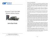
The location of the DIP-switches is shown in below.
DIP-switch Location
The functions of DIP-switch Bank 1 are outlined in below.
Switch Left
(Factory Default) Right
SW1 Off:
Pause Disable
PAUS:
Pause Enable
SW2 FDX:
Fiber Full-Duplex
HDX:
Fiber Half-Duplex
SW3 AN:
RJ-45 Auto-Negotiate
MAN:
RJ-45 Manual
SW4 100:
RJ-45 100Mbps
10:
RJ-45 10Mbps
SW5 FDX:
RJ-45 Full-Duplex
HDX:
RJ-45 Half-Duplex
SW6 - SW8 See Link Mode Selection
DIP-switch BANK 1 Denitions
SW1 - RJ-45/Fiber Pause
When this DIP-switch is in the Left “OFF” position, Pause
is disabled. When the DIP-switch is in the Right “PAUS”
position Pause is enabled.
When a port is congured for Auto-Negotiation (AN),
Pause operation is determined during the negotiation
process between itself and the link partner. The port
advertises its Pause capability (Symmetrical or No Pause)
based on the Pause Disable/Enable DIP-switch setting.
When a port is operating in Manual mode (MAN), its Pause
operation mode is based on the Pause Disable/Enable
DIP-switch setting.
SW2 - Fiber Full/Half Duplex
Setting this DIP-switch to Half-Duplex “HDX” facilitates a
connection that supports Half-Duplex. Setting this DIP-
switch to Full-Duplex “FDX” facilitates a connection that
supports Full-Duplex operation.
SW3, SW4 and SW5 - RJ-45 Mode of Operation
DIP-switches SW3, SW4 and SW5 control the setting of
the RJ-45 port.
SW3 SW4 SW5 RJ-45 Mode of Operation
AN 100 FDX
The RJ-45 port is set to auto-negotiation
with the following modes advertised:
100F, 100H, 10F, 10H
AN 100 HDX
The RJ-45 port is set to auto-negotiation
with the following modes advertised:
100H, 10F, 10H
AN 10 FDX
The RJ-45 port is set to auto-negotiation
with the following modes advertised:
10F, 10H
AN 10 HDX The RJ-45 port is set to auto-negotiation
with the following modes advertised: 10H
MAN 100 FDX The RJ-45 port is set to manual
negotiation and is forced to: 100F
MAN 100 HDX The RJ-45 port is set to manual
negotiation and is forced to: 100H
MAN 10 FDX The RJ-45 port is set to manual
negotiation and is forced to: 10F
MAN 10 HDX The RJ-45 port is set to manual
negotiation and is forced to: 10H
RJ-45 Port - Mode of Operation
DIP-Switch Bank 2
The functions of DIP-switch Bank 2 are outlined below.
Switch Left
(Factory Default) Right
SW1 A-DS:
Disable Backplane A
A-EN:
Enable Backplane A
SW2 B-DS:
Disable Backplane B
B-EN:
Enable Backplane B
SW3 Reserved Reserved
SW4 M/SL:
Master/Slave Auto
SL:
Slave-Mode Only
SW5 - SW8 Reserved Reserved
DIP-switch Bank 2 Denitions
SW1, SW2 - Backplane Enable
When the DIP-switch is in the Left “DS” position (factory
default), the Backplane Port of the 10/100M2 is isolated
from the chassis’ Ethernet Backplane. When the
DIP-switch is in the Right “EN” position, the Backplane Port
is enabled. This allows Ethernet Backplane connectivity
to an adjacent module via the chassis Backplane Link “A”
or “B” depending on the switch setting.
SW4 - Master/Slave
When the 10/100M2 module is installed in a chassis with
an Network Management Module (NMM2), set the DIP-
switch to the Left “M/SL” position (factory default). The
assignment of mastership is automatically negotiated by
the installed management modules. To designate the
10/100M2 module as the master of the chassis, set the
DIP-switch on the module to the LEFT “M/SL” position, and
set the other installed management modules’ DIP-switches
to the Right “SL” position to enable Slave-Only mode.
SW3, SW5, SW6, SW7, SW8 - Reserved
These DIP-switches are for factory use only and must
always remain in the Left position (factory default).
SW6, SW7, SW8 - Link Modes
These three DIP-switches congure the link mode settings.
It is recommended to have link modes Left (default) during
the initial installation. After the circuit has been tested and
operational, congure the module for the desire mode.
For detailed information on the operation of the different
Link Modes, download the application note “iConverter
Link Modes”.
SW6 SW7 SW8 Link Mode Selection
Left Left Left Link Segment (LS)
(Factory Default)
Right Left Left Link Propagate (LP)
Left Right Left Remote Fault Detect + Link
Segment (RFD + LS)
Right Right Left Remote Fault Detect + Link
Propagate (RFD + LP)
Left Left Right Symmetrical Fault Detect (SFD)
Right Left Right Asymmetrical Link Propagate
Port 1 to Port 2 (ALP P1-P2)
Left Right Right Asymmetrical Link Propagate
Port 2 to Port 1 (ALP P2-P1)
Right Right Right Asymmetrical RFD + LP
Link Modes
Software Controlled Switch Settings
Additional settings are available via software control.
The following software settings can be controlled via
Serial Console/Telnet Console, NetOutlook Management
Software or other third-party SNMP-based clients:
• DIP-switch Conguration
• Port 1 and Port 2 Conguration
• 802.1ad Q-in-Q, QoS and Port Access Control
• MIB statistics
• Bandwidth control (rate limiting)
• Congurable Link Fault Propagation modes
The module can be congured by attaching the serial
port to a DB-9 serial (RS-232) equipped computer with
terminal emulation software such as ProComm or Putty.
The Serial Console Port (DCE) is a mini DIN-6 female
connector which can be changed to a DB-9 connector with
the included adapter. Attach the ends of a serial cable to
the serial port of the PC and the Serial Console Port of
the module. The port is a standard RS-232 asynchronous
serial interface with the following settings.
Bits Per Second 57,600
Stop Bits 1
Data Bits 8
Parity NONE
Hardware Flow Control NONE
The default password is public.
When using Telnet or SNMP, the default IP address for the
module is 192.168.1.220.
For more information on using and configuring the
Advanced Features, register for access to the NetOutlook
Management Software user manual or the 10/100M2 full
user manual.
Page 1 Page 2 Page 3 Page 4 Page 5 Page 6
Safety Warnings and Cautions
ATTENTION: Observe precautions for handling
electrostatic discharge sensitive devices.
WARNING: Potential damage to equipment and
personal injury.
WARNING: Risk of electrical shock.
Customer Support Information
Phone: (949) 250-6510
Fax: (949) 250-6514
Address: Omnitron Systems Technology, Inc.
38 Tesla
Irvine, CA 92618, USA
Email: [email protected]
URL: www.omnitron-systems.com
040-8900N-002F 3/23
LED Indicators
LED Color Description
Power
“PWR” Green OFF: No power applied or faulty
ON: Module has power
Power
Status
“PSx”
Green
OFF: Power Supply not installed
ON: Power Available
Blinking: No power available from “PSx”
P1 Activity
“FO” Green OFF: No ber link
Blinking Green: Data activity
Master
“BP” Green OFF: Slave Mode
ON: Master Mode
P2 Speed
“10” Green
OFF: Port is not linked at 10M
Solid Green: Port linked at 10M
Blinking Green: Data activity
P2 Speed
“100” Green
OFF: Port is not linked at 100M
Solid Green: Port linked at 100M
Blinking Green: Data activity
P2 Duplex
“FDX” Green OFF: Half-Duplex
ON: Full-Duplex
Specications
Description
iConverter 10/100M2
10/100BASE-TX Copper to 100BASE-X Fiber Media
Converter and Network Interface Device
Standard
Compliances
IEEE 802.3, 802.1Q, 802.1p, 802.1ad, 802.3ah
RFC 2819 (RMON), 2863, 2131
MEF 9, 14, 21
Regulatory
Compliances
Safety:
EMI:
ACT:
UL, CE, NEBS Level 3, UKCA
FCC Class A,
TAA, BAA, NDAA
Environmental RoHS, WEEE, REACH
Management IPv4, Telnet, SNMPv1, SNMPv2c, SNMPv3, Serial
Console
Frame Size Up to 2,048 bytes
Port Types
Copper:
Fiber:
Serial:
10/100BASE-T (RJ-45)
100BASE-X (SFP, ST, SC, LC)
RS-232 (Mini DIN-6 female)
Mini DIN-6 to DB-9 adapter included
Cable Types
Copper:
Fiber:
Serial:
EIA/TIA 568A/B, Cat 5 UTP and higher
Multimode: 50/125µm, 62.5/125µm
Single-mode: 9/125µm
RS-232, 22 to 24 AWG, 12 to 50 pF/ft
DC Power
Requirements
DC Input:
(Backplane)
3.3VDC, 1.4A @ 3.3VDC
Dimensions
W x D x H 0.85” x 4.5” x 2.8” (21.6 mm x 114.3 mm x 71.1 mm)
Weight 8 oz. (226.8 grams)
Temperature
Commercial:
Wide:
Extended:
Storage:
0 to 50°C
-40 to 60°C
-40 to 75°C
-40 to 80°C
Humidity 5 to 95% (non-condensing)
Altitude -100m to 4,000m
MTBF (hrs) 550,000
Warranty Lifetime warranty and 24/7/365 free Technical Support
/