Page is loading ...

W0303A
TM
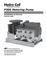
P500 Metering Pump
P500-991-2400A
Installation, Operation & Maintenance
1204 Chestnut Avenue, Minneapolis, MN 55403
Tel: (612) 332-5681 Fax: (612) 332-6937
Toll-free fax [US only]: (800) 332-6812
www.hydra-cell.com/metering
email: sales@wannereng.com

2P500-991-2400A
P500 Contents
Component Identication
Oil Fill Cap ID Plate
Outlet
Reducer
Inlet
Pump Assembly
Fluid End
Pump Assembly
Hydraulic End
Oil Drain
Diaphragms per Liquid End 5 (non Kel-Cell pistons)
Flow Control Electronic variable speed drive
Steady State Accuracy ±1%
Linearity ±3%
Repeatability ±3%
Maximum Pressure
Metallic Head: 2500 psi (173 bar)
Maximum Inlet Pressure 500 psi (35 bar)
Fluid Operating Temperatures*
Metallic Head: 250°F (121°C)
* Consult factory for correct component selection for
temperaturesfrom160˚F(71˚C)to250˚F(121˚C).
Inlet Port 1 1/4 inch NPT or BSPT
Discharge Port 3/4 inch NPT or BSPT
Maximum Solids 500 microns
Shaft Rotation Bi-directional
Materials Used See Replacement Parts Kits Section
forindividualpumpmaterials.
Oil Capacity 2.2USquart(2.1liters)
Weight
MetallicHead: 192.1lbs(87.1kg)
Page
Operation................................................................................2
Specications..........................................................................2
Dimensions.............................................................................4
Installation...............................................................................5
Calibration...............................................................................7
Maintenance............................................................................7
Fluid End Service ...................................................................8
Fluid End Parts List ..............................................................11
Hydraulic End Parts List .......................................................13
Hydraulic End Service ..........................................................14
Reducer Parts List.................................................................15
Troubleshooting.....................................................................17
Replacement Parts Kits........................................................18
Warranty................................................................................19
W0303A
P500 SpecicationsP500 Operation
Hydra-Cell Metering Solutions Pumps are hydraulically-
actuated, hydraulically-balanced diaphragm metering pumps
that exceed API 675 performance standards of ±1% steady state
accuracy,±3%linearityand±3%repeatability.
Due to their multiple diaphragm design, the P Series
meteringpumps,withtheexceptionoftheP100,providevirtually
“pulse-free”linearow.Unlikeconventionalsinglediaphragm
meteringpumps,thislinearowreducestheneedforpulsation
dampeners and increases the reliability, performance, and
safetyofthemeteringpumpsystem.
Pump operation and plunger activation are accomplished
throughacrankshaft(P100,P200andP300)orwobbleplate
(P400,P500andP600).Horizontaldiskcheckvalvesallowfor
the pumping of particulates that ordinarily collect on vertical
ball check valves common to conventional metering pumps.
P Series pumps utilize speed to adjust ow rate through a
motorandvariable-frequencydrive(VFD),eliminatingtheneed
formechanicaladjustment.

3P500-991-2400A
P500 Specications (Cont’d)
Performance Maximum Flow at Designated Pressure - Imperial *
*Capacity data shown is for pumps with elastomeric diaphragms. Consult factory for performance characteristics of pumps with PTFE diaphragms.
()RequiredMotorhp
Performance Maximum Flow at Designated Pressure - Metric *
*Capacity data shown is for pumps with elastomeric diaphragms. Consult factory for performance characteristics of pumps with PTFE diaphragms.
()RequiredMotorkW
Metallic Pump Heads (gph) Pump
rpm
Gear
Ratio
Motor
rpm
100 psi 500 psi 1500 psi 2500 psi
17.48(¼) 16.96(½) 15.74(1½) 14.47(1½) 30 60:1
1800
20.97(¼) 20.43(½) 19.11(1½) 17.71(2) 36 50:1
26.39(¼) 25.73(¾) 24.20(1½) 22.67(3) 45 40:1
35.27(¼) 34.47(¾) 32.63(2) 30.80(3) 60 30:1
42.37(¼) 41.47(¾) 39.37(2) 37.31(3) 72 25:1
53.03(¼) 51.97(¾) 49.49(2) 47.07(3) 90 20:1
70.78(½) 69.46(1) 66.35(3) 63.34(5) 120 15:1
106.3(½) 104.4(1½) 100.1(3) 95.88(5) 180 10:1
141.8(½) 139.4(1½) 133.8(5) 128.4(7½) 240 7.5:1
212.8(1) 209.4(2) 201.2(7½) 193.5(10) 360 5:1
283.9(1½) 279.4(3) 268.7(7½) 258.6(15) 480 7.5:1 3600
425.9(1½) 419.3(5) 403.6(15) 388.7(20) 720 5:1
Metallic Pump Heads (lph) Pump
rpm
Gear
Ratio
Motor
rpm
7 bar 34 bar 103 bar 172 bar
55.14(0.37) 53.50(0.75) 49.66(2.2) 45.641(3) 25 60:1
1500
66.16(0.37) 64.44(0.75) 60.28(2.2) 55.85(3) 30 50:1
83.25(0.37) 81.16(0.75) 76.32(2.2) 71.50(3) 37.5 40:1
111.26(0.37) 108.75(0.75) 102.92(2.2) 97.16(4) 50 30:1
133.66(0.37) 130.82(1.1) 124.19(2.2) 117.69(4) 60 25:1
167.27(0.37) 163.93(1.1) 156.11(2.2) 148.49(4) 75 20:1
223.28(0.55) 219.11(1.1) 209.29(3) 199.81(4) 100 15:1
335.31(0.75) 329.47(1.5) 315.67(4) 302.45(5.5) 150 10:1
447.33(1.1) 439.83(2.2) 422.05(4) 405.10(7.5) 200 7.5:1
671.4(1.5) 660.6(3) 634.8(7.5) 610.4(11) 300 5:1
895.4(3) 881.3(5.5) 847.6(7.5) 815.7(11) 400 7.5:1 3000
1343.5(4) 1322.7(7.5) 1273.1(11) 1226.3(11) 600 5:1

4P500-991-2400A
P500 Dimensions
P500 Models with Metallic Pumping Head
W0316A
1.50
(38.1)
13.90
(353.1)
13.00
(330.2)
14.50
(368.3)
24.00
(609.6)
22.00
(558.8)
Ø0.56
(14.3) 4X
G
D
C
E
A
B
H
1-1/4" NPT or
1-1/4" BSPT
3/4" NPT or
3/4" BSPT
F
10.13
(257.2)
4.84
(122.8)
I
Input Frame
Size A B C D E F
G
(Square
Key)
H I
NEMA 56C 21.76(552.6) 19.05(495.3) Ø6.54(Ø166) Ø4.50(Ø114.3) Ø0.62(Ø15.7) 13.22(335.9) 0.187(4.75) 13.53(343.7) 11.36(288.5)
NEMA
143/145 TC 21.76(552.6) 19.05(495.3) Ø6.54(Ø166) Ø4.50(Ø114.3) Ø0.87(Ø22.2) 13.22(335.9) 0.187(4.75) 13.53(343.7) 11.36(288.5)
NEMA
182/183TC 26.07(585) 20.36(517.1) Ø9.17(Ø233) Ø8.50(Ø218.9) Ø1.12(Ø26.6) 13.77(349.75) 0.25(6.35) 14.84(376.9) 12.68(322)
IEC 71 B5 21.64(549.7) 18.93(480.8) Ø6.54(Ø166) Ø4.33(Ø110) Ø0.55(Ø14) 13.42(340.7) 0.196(5) 13.41(340.6) 11.24(285.4)
IEC80B5 22.42(569.6) 19.71(500.6) Ø7.87(Ø200) Ø5.12(Ø130) Ø0.75(Ø19) 13.42(340.7) 0.236(6) 14.20(360.6) 12.02(305.3)
IEC 90 B5 22.42(569.6) 19.71(500.6) Ø7.87(Ø200) Ø5.12(Ø130) Ø0.94(Ø24) 13.42(340.7) 0.314(8) 14.20(360.6) 12.02(305.3)
IEC 100/112
B14 21.64(549.7) 18.93(480.8) Ø6.30(Ø160) Ø4.33(Ø110) Ø1.10(Ø28) 13.42(340.7) 0.314(8) 13.41(340.6) 11.24(285.4)
Dimensions in Inches (Millimeters)

5P500-991-2400A
P500 Installation
Location
Locatethepumpasclosetothesupplysourceaspossible.
Installthepumpsysteminalightedcleanspacewhereitwillbe
easytoinspectandmaintain.
Motor and Controller
The P Series pump shaft can rotate in either direction,
thereforedirectionofmotorshaftrotationisnotcritical.
Flow rateisdeterminedbymotorspeed,whichiscontrolled
using an inverterdutyconstant torquemotorand VFD. Flow
ratefunctionscanalsobeeasilycontrolledusingtheHydra-Cell
ControlFreakandappropriatemotor.
Accessories
Consult installation drawing below for typical metering uid
system components. Contact Wanner Engineering or the
distributorinyourareaformoredetails.
W0323A
(To process)
Pulsation
Dampener
(Optional)
Relief
Valve
Flanges & Manifolds
Ball Valve
Y-Strainer
Isolating
Valve
Calibration
Cylinder
Pressure
Gauge
Back Pressure
Valve
P-Series
Metering Pump
Typical Metering Installation
Controllers
& Motors
Important Precautions
Adequate Fluid Supply. To avoid cavitation and
prematurepumpfailure,besurethatthepumpwillhave
anadequateuidsupplyandthattheinletlinewillnotbe
obstructed.SeeInlet Piping.
Positive Displacement. This is a positive-displacement
pump.Toavoidseveresystemdamageifthedischargeline
everbecomesblocked,installareliefvalvedownstream
fromthepump.SeeDischarge Piping.
Safety Guards.Followallcodesandregulationsregarding
installationandoperationofthepumpingsystem.
Shut-O Valves. Never installshut-o valves between
thepumpandreliefvalve,orintheregulatorbypassline.
ConsulttheFactoryforthefollowingsituations:
• Extreme temperature applications (above 160°F or
below40°F)
• Pressurefeedingofpumps
• Viscousorabrasiveuidapplications
• Chemical compatibility problems
• Hot ambient temperatures (above 110°F)

6P500-991-2400A
P500 Installation (Cont’d)
Inlet Piping
Provide for permanent or temporary installation of a compound
pressure gauge to monitor the inlet pressure. To maintain
maximumow,thepumpinletshouldbeunderoodedsuction
conditionsatalltimes.Do not supply more than one pump
from the same inlet line.
Supply Tank
Useasupplytankthatislargeenoughtoprovidetimeforany
trappedairintheuidtoescape.Thetanksizeshouldbeat
leasttwicethemaximumpumpowrate.
Installaseparateinletlinefromthesupplytanktoeachpump.
Placeacoveroverthesupplytank,topreventforeignobjects
fromfallingintoit.
Hose Sizing and Routing
Tominimizeacceleration head andfrictionallosses,sizethe
suctionlineat least one sizelargerthanthe pump inlet,and
keepthesuctionlineasshortanddirectaspossible.
Recommendations:
• Keepinletlineslessthan3ft.(1m)long
• Useatleast1-1/2”(38mm)I.D.inlethose
• Minimizettings(elbows,valves,tees,etc.)
Inlet Piping (Pressure Feed)
Provide for permanent or temporary installation of a pressure
gaugetomonitortheinletpressure.Pressureatthepumpinlet
shouldnotexceed500psi(35bar).Forhigherpressuresinstall
apressurereducingvalve.Do not supply more than one pump
from the same inlet line.
Note: System back pressure must exceed the pump inlet
pressure by at least 15 psi (1 bar) in order to prevent ow
thru.
Discharge Piping
Hose and Routing
Usetheshortest,most-directrouteforthedischargeline.
Selectpipeorhosewithaworking pressure ratingofatleast
1.5timesthemaximumsystempressure.Example:Selecta
1500psi(103bar)W.P.-ratedhoseforsystemstobeoperated
at1000psi(69bar)gaugepressure.
Supportthepumpandpipingindependently.
Pressure Regulation
Install a pressure relief valve in the discharge line. Bypass
pressuremustnotexceedthepressurelimitofthepump.
Sizethevalvesothat,whenfullyopen,itwillbelargeenough
torelievethefullcapacityofthepumpwithoutover-pressurizing
thesystem.
Locate the valve as close to the pump as possible and ahead
ofanyothervalves.
Adjustthepressurereliefvalvetonomorethan10%overthe
maximumworkingpressureofthesystem.Donotexceedthe
manufacturer’spressureratingforthepumporvalve.
Routethebypasslinetothesupplytank.
CAUTION: Never install shuto valves in the bypass line
or between the pump and pressure regulator or relief valve.
Provide for permanent or temporary installation of a pressure
gaugetomonitorthedischargepressureatthepump.
Minimum Discharge Pressure
To ensure proper capacity control, a minimum discharge
pressureof50psi(3.5bar)isrequired.
Safety Precautions
General remarks
These safety / installation instructions contain fundamental
informationandprecautionarynotesandmustbekeptavailable
toallassociatedwiththeoperationofthepump.Pleaseread
themthoroughlypriortoinstallation,electricalconnectionand
commissioningoftheunit.Itisimperativethatallotheroperating
instructionsrelatingtothecomponentsofindividualunitsare
followed.
These safety / installation instructions do not take local
regulationsintoaccount.Theoperatormustensurethatsuch
regulationsareobservedbyall,includingthepersonnelcarrying
outtheinstallation.
Each pumpmustbe labeled bythe end userto warnofany
hazardsthatthesystemprocessmayproduce;e.g.corrosive
chemicalsorhotprocessetc.
All personnel involved in the operation, maintenance, inspection
andinstallationofthepumpmustbefullyqualiedtocarryout
the work. The personnel’s responsibilities, competence and
supervisionmustbeclearlydenedbytheoperator.Totheextent
thatifthepersonnelinquestionisnotalreadyinpossession
oftherequisiteknowhow,appropriatetrainingandinstruction
mustbeprovided.Inaddition,theoperatorisresponsiblefor
ensuringthatthecontentsoftheoperatinginstructionsarefully
understoodbyalltheresponsiblepersonnel.
WheninstallingaHydra-Cellpumpinconjunctionwithamotor
ormotorandfrequencycontrollertherelevantmanualsmust
bereferredtoforelectromagneticcompatibility.Theinstallation
shouldconformtoEN61800andEN60204asapplicable.
All safety instructions in this manual and all relevant local health
andsafetyregulationsmustbefollowed.
Attention must be paid to the weight of the pump before
attemptingtolifteithermanuallyorselectingappropriatelifting
equipment.

7P500-991-2400A
P500 Installation (Cont’d)
P500 Maintenance
Note: The numbers in parentheses are Reference Numbers
located in the Parts List exploded views of this manual.
Periodically
CAUTION: Do not turn the drive shaft while the oil reser voir
is empty.
CAUTION: Do not leave contaminated oil in the pump
housing or leave the housing empt y. Remove contaminated
oil as soon as discovered and replace with clean oil.
1. Checkinletpressureperiodicallywithgauge.
2. Changeoilaccordingtohoursguidelinesintable.
3. Changeoilasfollows:
a.Removebrasscap(26),andallowoiland
contaminantstodraincompletely.Catchoil
anddisposeofproperly.
b.UsesuitableHydra-Oilfortheapplicationand
pumpcomponents.
Pump Operation Hours Between Oil Changes
at Various Process Fluid Temperatures
<90°F <139°F <180°F
Pressure (32°C) (60°C) (82°C)
Metallic Pump Head
<1500 psi (104 bar) 4,000 3,000 2,000
<2500 psi (173 bar) 1,500 1,250 1,000
Note: Minimum oil viscosity for proper hydraulic end
lubricat ion i s 16-20 cST (80-100 SSU). P- Series replacement
parts kits (complete kits and diaphragm kits) include
suitable oil for each P Series pump conguration.
CAUTION: If you are losing oil but don’t see any external
leakage, or if the oil becomes discolored and contaminated,
the diaphragm (21) may be damaged. Refer to the Fluid End
Service and Troubleshooting Sections. Do not operate the
pump with a damaged diaphragm.
Initial Start-Up Procedure
Before you start the pump, be sure that:
1. Allshut-ovalvesareopen,andpumphasadequatesupply
ofuid.
2. Allconnectionsaretight.
3. The oil level is 1/4 inch (6 mm) above the cast surface in the
upperoilreservoir.
4. Openprimingvalveonsystembackpressurevalvesopump
starts under minimum pressure. See Typical Metering
Installationdrawing.
Turnonpowertopumpmotorand:
1. Checkinletpressureorvacuum.Tomaintainmaximumow,
pumpinletshouldbeunderoodedsuctionconditionsatall
times.Inletpressuremustnotexceed500psi(35bar).
2. Observeanyerraticnoiseorow.
3. Jogpumponandountiluidcomingfromprimingvalve
isair-free.
4. Closeprimingvalve.
5. Performpumpcalibration.SeeCalibrationProcedure.
Calibration
Note: Each metering pump or pump system must be calibrated
to deter mine the pump speed required for the desired ow rate.
Accurate calibration
dependsonpumpdischargepressureand
systemconditions.Whencalibratingthepumporsystem,itis
usefultoplotcapacitycurvesforfuturereference.Observeon
thecurve,thatpumpcapacitydecreasesslightlyasdischarge
pressureincreases.
In order to achieve the best possible results, perform calibration
underactualprocessconditions.Followthesesteps:
1. Run pump for 20 minutes at actual process conditions. If
processsystemcannotbeused,circulatebacktosupplytank
throughpressurereliefvalve(seeTypicalMeteringInstallation
drawing).Ifrequiredsystempressureislessthan50psi(3.5
bar)backpressurevalvemustbeinstalledandsettoproduce
minimumof50psi(3.5bar)pressureatpumphead.
2. Determine maximum pump speed required for all system
conditionsthatneedtobesatised.Measurepumpdelivery
atthismaximumspeedusingsystemcalibrationcylinder,ow
meter,orsimilarcontainer.Thisisthe“ratedcapacity”forpump.
3. Measurepumpdeliveryat100%,75%,50%,25%,and10%of
maximumspeedjustdetermined.Letpumprunfor5minutes
ateachspeedsettingbeforetakingcapacitymeasurement.

8P500-991-2400A
P500 Fluid End Service
Note: The reference numbers in parentheses are shown
in the Fluid End Parts List.
Thissectionexplainshowtodisassembleandinspectalleasily-
serviceablepartsofthepumpuidend.
Caution: Disassembly of the hydraulic end of the pump
should be performed only by a qualied technician. For
assistance, contact Wanner Engineering (612-332-5681) or
the distributor in your area.
CAUTION: Do not remove the four socket-head capscrews
(29)thatgothroughthecylinderhousing(23),unlessyouare
repairingthehydraulicendofthepump.
1. Remove Manifold (4),
Valve Plate (24)
a. Manifold (4.)Use8mmhexbitsocketincludedin
Wanner Tool Kit to remove 12 capscrews (2) and ve
capscrews(1)atfrontofmanifold.Removeandinspect
manifoldforwarpingorweararoundinletandoutletports
andowchannels.Ifwearisexcessivereplacemanifold.
Tocheckifmanifoldiswarped,placestraightedgeacross
it; check both sides. A warped manifold should be
replaced.
b. Valve Plate (24.)Using8mmhexbitsocketremove
capscrew(22).Removeandinspectvalveplate(inlike
manner as manifold) for excessive wear or warping.
Replaceifnecessary.
CAUTION: Don’t turn the pump drive shaft while the
manifold and valve plate are o the pump, except when
removing diaphragms or repriming the hydraulic cells.
2. Remove and Inspect
Valves (9-20)
Note: Wanner Valve Kits include items and all O-rings for
sealing the manifold to the valve plate. The ve inlet and
ve outlet valve assemblies are dierent in size and face
in opposite directions.
a. Remove inlet valve seat (10) using seat puller tool
includedinWannerToolKit.Inspectvalveseatforwear,
andreplaceifnecessary.
Note: Whenever any valve or seat is replaced it is
recommended to replace all valve assemblies to ensure
the most reliable operation. All necessary parts are
includedinareplacementValveKit.
b. Removeremaininginletvalvecomponents(11-14)and
outletvalvecomponents(17-20)byhandorwithsmall
needlenosepliers.
c. Check spring retainers (14, 20) and replace if worn,
cracked,ordamaged.
d. Checkvalvesprings(12,19)andreplaceifworn,broken,
orshorterthannewspring.Neverattempttostretchold
spring.
e. Checkvalves(11,18)forwearordamageandreplace
if necessary. Polishing of valves during operation is
normal.Ifyoucanfeelaridgeinvalvesurface,valve
shouldbereplaced.
Note:Pumpswithplasticspringretainers(14,20)include
Tetra Seal (13, 17 - square section O-ring) between
springretainerandvalveseat.Pumpswithmetalspring
retainersdonotincludeTetraSeal.
f. Reinstallvalveassemblies:
• Cleanvalveportsandshouldersinvalveplate(24)with
Scotch-Britepadorneemerycloth.Washvalveplate
aftercleaning,andlubricatevalveportswithcompatible
grease,oil,orpetroleumjelly.
• Install new O-rings (9, 15) on seats (10, 16) and
lubricateallO-rings.
• InletValves(vecenter,largervalves).Insertspring
retainer(14)intovalveplate(24),followedbyTetraseal
(13)ifspring retaineris plastic. Insert spring(12) into
retainer,followedbyvalve(11)onspring.Finally,insert
seat(10)withnewO-ringintovalveborewithlargerI.D.
chamfer(seatingsurface)facingdown,towardsvalve.
• OutletValves(veouter,smallervalves).Insertoutlet
seat(16)withnewO-ringintovalveborewithlargerI.D.
chamfer(seatingsurface)facingup.InsertTetraSeal
(17)ifvalvespringretainersareplastic.Insertvalve(18)
andspring(19)onseat.Finally,inser tspringretainer(20)
intovalvebore.
• Makesurespringsareallproperlynestedintospring
retainerstoensurepropervalveperformance.

9P500-991-2400A
P500 Fluid End Service (Cont’d)
3. Inspect and Replace
Diaphragms (21)
a.Lift diaphragm(21)byoneedge,and turnpump shaft
(use the shaft rotator from the Wanner Tool Kit) until
thediaphragmmovesupto“topdeadcenter”.This
willexposemachinedcross-holesinvalveplunger(51)
behinddiaphragm.
b. Insertplungerholder(from the Wanner Tool Kit)through
oneofmachinedcrossholestoholddiaphragmup.Don’t
remove tool until new diaphragm is installed in step f
below.
c. Unscrewdiaphragm(21).Usea5/16-in.(8-mm)open-
endwrench,andturncounterclockwise.
d.Remove diaphragm and inspect carefully. A damaged
diaphragm generally indicates a pumping system
problem. Replacing diaphragm only, will not solve the
largerproblem.Inspectdiaphragmforfollowing:
• Puncture.Usuallycausedbysharpforeignobjectin
uid.
• Diaphragm pulled awayfromcenterscreworfrom
cylindersides.Usuallycausedbyuidbeingfrozenin
pump,orbyover-pressurizationofpump.
• Diaphragm becoming stiff and losing flexibility.
Usuallycausedbypumpinguidthatisincompatiblewith
diaphragmmaterial.
• Diaphragm edge chewed away.Usuallycausedby
over-pressurizingsystem.
CAUTION: If a diaphragm has ruptured and foreign
material or water has entered the oil reservoir, do
not operate the pump. Check all diaphragms, then
ush the reservoir completely (as outlined below)
and rell it with fresh oil. Never let the pump stand
with foreign material or water in the reser voir, or with
the reservoir empty.
e.Cleanawayanyspilledoil.
f. Installnewdiaphragm(oroldone,ifnotdamaged),and
tightento10in.-lbs(110N-cm).
g.Repeataboveinspectionprocedure(andreplacement,
ifnecessary)withotherfourdiaphragms.
4. Flush Contaminant from
Hydraulic End
(only if a diaphragm has ruptured)
a.Withvalveplateandmanifoldstillremoved(seeabove),
removethebrasscap(26)allowalloilandcontaminant
todrainout.
b. Fillreservoirwithcompatiblesolvent.Manuallyturnpump
shafttocirculatecompatiblesolventanddrain.Usethe
shaftrotatorprovidedinWannerToolKit(PartNo.A03-
175-1103).Disposeofcontaminateduidproperly.
CAUTION: If you have an EPDM diaphragm, or if food
grade oil is in the reservoir, do not use kerosene or
solvents. Instead, ush with the same lubricant that
is in the reservoir.
c. Repeatstepbushingprocedure
d.Fillreservoirwithfreshoilandmanuallyturnpumpshaft
tocirculateoil.Drainoil.
Note: P Series replacement parts kits (complete kits
and diaphragm kits) include the correct oil for each
specic P Series pump conguration.
e.Rellreservoirwithfreshoil.Ifoilappearsmilky,thereis
stillcontaminantinreservoir.Repeatstepscandduntil
oilappearsclean.

10 P500-991-2400A
P500 Fluid End Service (Cont’d)
5. Prime Hydraulic Cells
a. With pump horizontal and the fluid end head
removed, ll reservoir with appropriate Hydra oil for
application. Have catch basin for oil that leaks from
behinddiaphragmswhenpriming.Catchoilanddispose
ofproperly;do not reuse.
b. Allairinoilwithinhydrauliccell(behinddiaphragm)must
be forced out by turning shaft (thus pumping piston).
ShaftRotatorisincludedinWannerToolKit.Rotateshaft
tworevolutionsandrellreservoir.Rotateittwomore
revolutionsandrellagain.Continuetodothisuntiloil
thatisbeingpumpedfrombackofallvediaphragmsis
freeofair.
c. Wipe excess oil from cylinder housing (23) and
diaphragms(21).
d. Ensurethatoillevelis1/4in(6mm)abovecastsurface
inupperoilreservoir.
e.Replaceoilllcap(28).
6. Reinstall Valve Plate (24),
Manifold (4)
a.Reinstallvalveplate(24),withvalveassembliesinstalled
asoutlinedabove,oncylinderhousingcenterspudand
alignmentpin(8).
b.Installcapscrew(22)withatwasher(3)throughcenter
holeinvalveplateandtorqueto45ft-lbs(60N-m).
c.InstallnewO-rings(5,6,7)intogroovesinfrontsideof
valveplate.Usegreaseorpetroleumjellytoholdinplace.
d.Reinstallmanifold(4)overalignmentpin(8),engaging
centerspudofmanifoldintocenterofvalveplate.
e.Installcapscrews(1)with atwashers(3)throughve
centerholesinmanifold.Threadeachcapscrewin
severalturns,butdonottorque.
f.Installcapscrews(2)withatwashers(3)throughtwelve
outer holes at perimeter of manifold. Thread each
capscrewinseveralturns,butdonottorque.
g. Return to ve capscrews at center of manifold and
alternately tighten opposite bolts until all are secure.
Torqueto45ft-lbs(60N-m).
h.Returntotwelvecapscrewsatperimeterofmanifoldand
alternately tighten opposite bolts until all are secure.
Torqueto45ft-lbs(60N-m).
i.Recheckallcapscrewsfortightnessandpropertorque,
starting with ve at center of manifold, then twelve at
perimeter.

11 P500-991-2400A
P500 Fluid End Parts List
20
DETAIL "A"
(Valve Assemblies)
Metal Retainer
OUTLET VALVE
Metal Retainer
INLET VALVE
1
3
5
6
7
4
3
2
30
32
31
26
37
28
29
23
8
21
3
22
24
34
27
34
33
0
Valve
Assemblies
(see Detail A)
W0317A
19
18
15
16
14
12
11
10
9
25
Bolt Torque Specications
Ref.No. AssemblyTorque
1 45 ft-lbs (60 N-m)
2 45 ft-lbs (60 N-m)
22 45 ft-lbs (60 N-m)
29 15 ft-lbs (20 N-m)
32 45 ft-lbs (60 N-m)

12 P500-991-2400A
P500 Fluid End Parts List (Cont’d)
0 D25-038-2017 Plug,HastelloyC,NPT.......................2
D25-038-2211 Plug,316SST,NPT............................2
G25-038-2017 Plug,HastelloyC,BSPT.....................2
G25-038-2211 Plug,316SST,BSPT..........................2
1 G15-081-2012 Screw,Cap,soc-hd,SST...................5
2 G10-024-2012 Screw,Cap,soc-hd,SST.................12
3 100-037 Washer, Flat, SST.............................18
4 D15-004-1010 Manifold, Brass, NPT..........................1
D15-004-1012 Manifold, 316L SST, NPT....................1
D15-004-1018 Manifold,HastelloyC,NPT.................1
G15-004-1010 Manifold, Brass, BSPT........................1
G15-004-1012 Manifold, 316L SST, BSPT..................1
G15-004-1018 Manifold,HastelloyC,BSPT...............1
5 D40-073-2110 O-ring,Outermanifold,Buna-N..........1
D40-073-2111 O-ring,Outermanifold,FKM...............1
D40-073-2118 O-ring,Outermanifold,PTFE.............1
6 D15-073-2110 O-ring,Middlemanifold,Buna-N........1
D15-073-2111 O-ring,Middlemanifold,FKM.............1
D15-073-2118 O-ring,Middlemanifold,PTFE...........1
7 D35-080-2120 O-ring,Innermanifold,Buna-N...........1
D35-080-2118 O-ring,Innermanifold,PTFE..............1
D35-080-2121 O-ring,Innermanifold,FKM...............1
8 D15-026-2210 Pin,Dowel...........................................1
9 D10-035-2110 O-ring,Inletvalveseat,Buna-N..........5
D10-035-2111 O-ring,Inletvalveseat,FKM..............5
D10-035-2118 O-ring,Inletvalveseat,PTFE.............5
10 D15-020-1011 ValveSeat,Inlet,Nitronic50...............5
D15-020-1016 ValveSeat,Inlet,Tungstencarbide......5
D15-020-1017 ValveSeat,Inlet,HastelloyC..............5
11 D10-021-1011 Valve,Inlet,Nitronic50.......................5
D10-021-1016 Valve,Inlet,Tungstencarbide..............5
D10-021-1017 Valve,Inlet,HastelloyC......................5
12 D10-022-3117 ValveSpring,Inlet,Elgiloy...................5
D10-022-3123 ValveSpring,Inlet,HastelloyC...........5
14 D10-023-1017 Retainer,Inletvalvespring,
Hastelloy C..........................................5
15 D25-046-2110 O-ring,Outletvalveseat,Buna-N.......5
D25-046-2111 O-ring,Outletvalveseat,FKM...........5
D03-035-2118 O-ring,Outletvalveseat,PTFE..........5
16 D15-020-2011 ValveSeat,Outlet,Nitronic50............5
D15-020-2016 ValveSeat,Outlet,Tungstencarbide....5
D15-020-2017 ValveSeat,Outlet,HastelloyC...........5
18 D03-021-1011 Valve,Outlet,Nitronic50....................5
D03-021-1016 Valve,Outlet,Tungstencarbide...........5
D03-021-1017 Valve,Outlet,HastelloyC...................5
19 D15-022-3113 ValveSpring,Outlet,HastelloyC........5
D15-022-3114 ValveSpring,Outlet,Elgiloy................5
20 D03-023-1017 Retainer,Outletvalvespring,
Hastelloy C..........................................5
21 D15-018-1220 Diaphragm,Buna-N............................5
D15-018-1215 Diaphragm,FKM.................................5
D15-018-1225 Diaphragm,Aas.................................5
22 G10-087-2010 Screw,Cap,soc-hd..............................1
23 G15-002-1000 CylinderHousing.................................1
24 D15-003-1010 ValvePlate,Brass...............................1
D15-003-1012 ValvePlate,316LSST.........................1
D15-003-1018 ValvePlate,HastelloyC......................1
25 D25-077-2210 Pipe, Brass..........................................1
26 D25-078-2210 PipeCap,Brass..................................1
27 D10-080-2110 O-ring,Buna-N....................................1
28 D03-039-1030 CapwithO-ring,Oilll........................1
29 C22-015-2014 Screw,Cap,soc-hd..............................4
30 D15-025-1033 Base Plate...........................................1
31 G35-084-2010 Lockwasher.........................................4
32 G35- 087-2010 Screw,Caphex-hd............................................ 4
33 D35-111-2010 Plug,Magnetic.....................................1
34 D25-038-2210 Plug,Brass..........................................2
37 G15-001-1033 PumpHousing.....................................1
Ref. Quantity/
No. Part Number Description Pump
Ref. Quantity/
No. Part Number Description Pump

13 P500-991-2400A
P500 Hydraulic End Parts List
40
39
41
42
43
44
45
46
37
38
43
43
43
A
B
47
48
49
50
51
52
53
54
56
23
*
*
Qty per piston: 4
55
57
Cross-Section
Assembly
W0086
Bolt Torque Specications
Ref.No. AssemblyTorque
40 15 ft-lbs (20 N-m)

14 P500-991-2400A
38 D15-075-3110 Spring,Disk.........................................6
39 D15-112-1010 Guide,Diskspring...............................1
40 G15-115-2010 Screw,Cap,soc-hd.............................1
41 D15-012-1010 Plate,Bearingadjustment...................1
42 D15-110-2210 Pin,Dowel...........................................1
43 D15-007-1210 (X) Cam Assembly (1).........................1
44 D25-085-2210 Key,Shaft............................................1
45 H25-031-2112 Seal shaft............................................2
46 D15-037-2110 O-ring,Buna-N....................................1
47 D10-019-3110 Spring,Pistonreturn...........................5
48 D10-042-1010 Retainer,Spring..................................5
49 D10-046-2110 O-ring,Buna-N....................................5
50 D10-045-3110 Spring,Sleevevalve............................5
51 D15-044-1010 Plunger,Valve.....................................5
Ref. Quantity/
No. Part Number Description Pump
(1) CamAssemblyincludescam,shaft,wobbleplate,bearings,
andcups.Itisonlyavailableasanassembly.
(2)PistonAssemblyincludesitems47through55.
P500 Hydraulic End Parts List (Cont’d)
Hydraulic End Service
CAUTION: Disassembly of the hydraulic end of the pump
should be performed only by a qualied technician. For
assistance, contact Wanner Engineering (612-332-5681) or
the distributor in your area.
52 D10-043-1010 Cylinder,Valve....................................5
53 D10-034-2110 O-ring,Buna-N....................................5
54 D10-041-1010 Washer,Retaining...............................5
55 D10-015-3010 Ball, Steel......................................... 20
56 D15-014-1209 Piston(withfoot,retainerandballs)....5
57 D15-014-1210 Piston Assembly, Buna-N (2)..............5
Ref. Quantity/
No. Part Number Description Pump

15 P500-991-2400A
Ref Quantity/
No. Part Number Description Pump
1 P5-N-PUMP P500PumpAssembly,NPT..................
P5-M-PUMP P500PumpAssembly,BSPT................
2 112-055 Key,1/4sqx3.5..................................1
3 112-528 Shaft....................................................1
4 112-035 Shaft Kit...............................................1
5 112-500 Reducer, 5:1 ratio ...............................1
112-501 Reducer,7.5:1ratio............................1
112-502 Reducer, 10:1 ratio .............................1
112-503 Reducer, 15:1 ratio .............................1
112-537 Reducer, 20:1 ratio .............................1
112-538 Reducer,25:1ratio.............................1
112-549 Reducer, 30:1 ratio .............................1
112-539 Reducer, 40:1 ratio .............................1
112-540 Reducer, 50:1 ratio .............................1
112-541 Reducer, 60:1 ratio .............................1
W0352A
1
10
8
4*
9
16
12
6**
6** 10
6**
11
7
13
14
7
2
3
4*
4*
Notes: * Item Shaft Kit parts for item 3.
4*
** Item consists of one Input Flange Kit
and attaching parts.
6**
5
15
6 112-520 FlangeKit,Input,NEMA56C..............1
112-521 FlangeKit,Input,NEMA143/145TC...1
112-522 FlangeKit,Input,NEMA182/184TC. . 1
112-562 FlangeKit,Input,IEC71B5................1
112-506 FlangeKit,Input,IEC80B5...............1
112-551 FlangeKit,Input,IEC90B5...............1
112-552 FlangeKit,Input,IEC100/112B14.....1
7 112-526 Washer, Flat, M10, SST......................8
8 G25-029-2011 Screw,M10,1.5x25mm,HHCS........4
9 100-989 Screw,3/8-16x1.75,HHCS...............4
10 G10-029-2022 Screw,M10,1.5x30mm,HHCS........4
11 112-031 Washer,Flat,wide,typeA,3/8...........8
12 100-032 Locknut,M10x1.5,SST.....................5
13 D10-087-2012 Screw,3/8-16x1.125,HHCS..............4
14 D10-048-2012 Lockwasher,SST,182/184TC.............4
15 112-519 Support,SST,182/184TC...................2
16 112-517 Base,182/184TC.................................1
P500 Reducer Parts List (1 of 2)
Ref Quantity/
No. Part Number Description Pump

16 P500-991-2400A
Ref Quantity/
No. Part Number Description Pump
1 P5-N-PUMP P500PumpAssembly,NPT..................
2 112-700 Reducer, 5:1 ratio, 213/215TC............1
112-701 Reducer,7.5:1ratio,213/215TC.........1
112-800 Reducer,5:1ratio,254/256TC............1
3 112-821 Guard,213/215TC...............................1
112-822 Guard,254/256TC.............................. 1
4 A04-116-2201 Hub,Coupling,213/215TC..................1
A04-118-2201 Hub,Coupling,254/256TC..................1
5 A04-115-2200 Sleeve,Coupling,213/215TC..............1
A04-117-2200 Sleeve,Coupling,254/256TC..............1
1
12
4
5
6
2
3
14
10
11
8
7
W0359A
13
9
Ref Quantity/
No. Part Number Description Pump
6 A04-116-2205 Hub,Coupling,213/215TC..................1
A04-118-2203 Hub,Coupling,254/256TC..................1
7 100-989 Screw,3/8-16x1.75,HHCS................4
8 C22-018-3102 Washer,Flat,SST................................4
112-031 Washer,Flat,wide,3/8”,TypeA..........4
9 100-913 Screw,SST..........................................8
10 D10-048-2012 Lockwasher,3/8”,SST........................8
11 112-717 Base....................................................1
12 D25-085-2210 Key,1/4sqx1.4..................................1
13 S1258-024 Screw,1/2-13UNCx1.5,HHCS,SST.....4
14 M10-111-2000 Washer,Splitlock,steel......................4
P500 Reducer Parts List (2 of 2)

17 P500-991-2400A
P500 Troubleshooting
Problem Probable Cause Solution
Motor/Pump
Does Not
Operate:
Nopower. Supplycorrectpoweraccordingtomotorrequirements.
Blownfuse/trippedcircuit
breaker.
Replace/reset,eliminatecircuitoverload.
Shaftcouplingtopumpnotin
place.
Installpropercouplinghardware(seepartslist).
Currentoverload-motor. Motornotratedforpumpoperatingconditions-installpropermotor.
Thermaloverload-motor. Motornotratedforpumpand/orambientoperatingconditions-supply
coolingorinstallpropermotor.
Faultymotordrive/controller. Repair/replace.
Faultymotor. Repair/replace.
Lowliquidlevelinsupplytank
(iflow-levelshut-oisused).
Filltank.
No Delivery
Supplytankempty. Filltank.
Loss of prime Re-primeusingInitialStart-UpProcedure.
Inletlineorstrainerclogged. Cleardebrisandush,orreplace.
Inadequatesupplypressureat
pumpinlet.
Increasesupplypressurebyraisinguidlevelintank,raisingtank,or
pressurizingsuctiontank.
Inletlinetoorestrictive. Increaseinletlinediameterand/ordecreaseinletlinelength.
Fluidviscositytoohigh. Reduceviscosityifpossible(byheatorsomeothermeans).Increaseinlet
linediameterand/ordecreaseinletlinelength.Increasesupplypressure.
Vaporlock/cavitation. Increaseinletpressure.Decreaseuidtemperature.
Pump valves held open or
wornout.
Cleardebrisandush,orreplace(seeFluidEndService)
Systemreliefvalveactuating. Adjustreliefvalve,orrepair,clean,orreplacewithnewreliefvalve.
Delivery Too
Low and/or
Erratic
ReviewallProbableCausesandSolutionsinProblem2NoDeliveryabove.
Airleak(s)ininletline. Locateallleaksandrepair.
Systembackpressuretoolow. Adjustbackpressurevalvetohighersetting.Installbackpressurevalveif
noneinsystem.
Pumpeduidcharacteristics
changed.
Monitorsupplytanktemperaturetodetermineifuidistoohot(leadingto
cavitation)ortoocold(increasinguidviscosity).Stabilizetemperatureat
suitableleveltoresolveproblem.Checkforentrappedairintheuidsupply
system.
Inletsupplypressurechanged. Monitorinletsupplypressure(atthepump)todetermineifitistoolow,
causingastarvedcondition/cavitation.Stabilizepressureatsuitablelevel
toresolveproblem.
Pump OK - Calibration system
orowmetererror.
Evaluatecomponentsandrepair/correctproblem(s).
Oil condition in pump hydraulic
endchanged.
Checkoillevel-iflowevaluateforsourceofleakage.Consultfactoryfor
hydraulicendservice.
Changeoilperrecommendedguidelinesinmaintenancesection.
Delivery Too
High and/or
Erratic.
Systembackpressuretoolow. Adjustbackpressurevalvetohighersetting.Installbackpressurevalveif
noneinsystem.
Inletsupplypressurechanged. Monitorinletsupplypressure(atthepump)todetermineifitistoohigh,
causinga“ow-through”condition.Stabilizepressureatsuitablelevelto
resolveproblem.
Pump OK - Calibration system
orowmetererror.
Evaluatecomponentsandrepair/correctproblem(s).

18 P500-991-2400A
P500 Replacement Parts Kits
1-2 Pump Conguration
P5 For all P500 Pumps
3 Kit Designator
K Complete Fluid End Kit*
D DiaphragmKit*
V ValveKit(diaphragmnotincluded)
4-5 Pump Head Version
51 Standard
6 Spring Retainers (Dampening Washers)
B For brass pump head (Hastelloy C)
S For 316L Stainless Steel pump head
(Hastelloy C)
T For Hastelloy C pump head (Hastelloy C)
X NotincludedinDiaphragmKit
7 Diaphragm & O-ring Material
A Aas(Syntheticoil)
G FKM (Standard oil)
S FKM (Food-contact oil) ...
X FKM (Synthetic oil)
T Buna-N (Standard oil)
F Buna-N (Food-contact oil)
Y Buna-N (Synthetic oil)
8-9 Check Valve Material
(Spring/ Valve Seat / Valve)
SS Elgiloy/Nitronic50/Nitronic50
TT Hastelloy C / Hastelloy C/ Hastelloy C
SD Elgiloy/TungstenCarbide/TungstenCarbide
TD HastelloyC/TungstenCarbide/
TungstenCarbide
XX NotincludedinDiaphragmKit
6 953
2
184 7
Order
Digit Code Description
TOORDERREPLACEMENTPARTSKIT:AReplacementPartsKitcontains9digitscorrespondingtocustomer-specieddesignoptions.
* K&D Kits include hydraulic end oil: oil not included in V Kit.
Kit Contents
* Last four digits of part numbers with –_ _ _ refer to specic
material of construction.
Kit Designator
Part Number* Description Qty K D V
D15-018-___ Diaphragm 5
• •
D40-073-___ O-ring, outer manifold 1 • • •
D15-073-___ O-ring, middle manifold 1 • • •
D35-080-___ O-ring, inner manifold 1 • • •
D10-035-___ O-ring, valve seat, inlet 5 • •
D15-020-___ Valve seat, inlet 5 • •
D10-021-___ Valve, inlet 5 • •
D10-022-___ Valve spring, inlet 5 • •
D10-023-___ Retainer, valve spring, inlet 5 • •
D25-046-___ O-ring, valve seat, outlet 5 • •
D15-020-___ Valve seat, outlet 5 • •
D03-021-___ Valve, outlet 5 • •
D03-022-___ Valve spring, outlet 5 • •
D10-023-___ Retainer, valve spring, outlet 5 • •
A01-113-3400 Threadlocker 1
• •
Hydraulic End Oil (2.5 qt)
1 A03-125-1010 Holder,Plunger...........................................1
2 A03-195-1200 Rotator, Shaft..............................................1
3 A03-162-1010 Lifter,Plungerguide................................... 1
4 A03-124-1200 Lever Assembly .........................................1
5 A03-156-1200 Assembly studs..........................................1
6 A03-158-1002 SealProtector...........................................1
8 A03-155-1200 Inserter/Rotator..........................................1
7 A03-126-1500 Tool Box .....................................................1
Ref. P500 Quantity/
No. Tool Part No. Tool Description Kit
P500 Tool Kit
TheP500ToolKit(PartNo.A03-175-1103)containsthetoolslisted
below.Thesetoolsareusedtoassistintherepairandmaintenance
oftheP500.Seethemaintenancesectionsofthismanualfor
specicapplication.

19 P500-991-2400A
Limited Warranty
WannerEngineering,Inc.extendstotheoriginalpurchaser
ofequipmentmanufacturedbyitandbearingitsname,a
limitedone-yearwarrantyfromthedateofpurchaseagainst
defects in material or workmanship, provided that the
equipmentisinstalledandoperatedinaccordancewiththe
recommendationsandinstructionsofWannerEngineering,
Inc.WannerEngineering,Inc.willrepairorreplace,atits
option, defective parts without charge if such parts are
returned with transportation charges prepaid to Wanner
Engineering, Inc., 1204 Chestnut Avenue, Minneapolis,
Minnesota55403.
Thiswarrantydoesnotcover:
1. The electric motors (if any), which are covered by
the separate warranties of the manufacturers of these
components.
2. Normal wear and/or damage caused by or related to
abrasion, corrosion, abuse, negligence, accident, faulty
installationortamperinginamannerwhichimpairsnormal
operation.
3.Transportationcosts.
This limited warranty is exclusive, and is in lieu of any
other warranties (express or implied) including warranty
of merchantability or warranty of tness for a particular
purpose and of any non-contractual liabilities including
product liabilities based on negligence or strict liability.
Every form of liability for direct, special, incidental or
consequentialdamagesorlossisexpresslyexcludedand
denied.
P500 Warranty

2020
©2007WannerEngineering,Inc.PrintedinUSA
P500-991-2400A 3/2007, Revised 3/2016
World Headquarters & Manufacturing
WannerEngineering,Inc
1204 Chestnut Avenue,
Minneapolis,MN55403USA
Phone:612-332-5681●Fax:612-332-6937
Toll-FreeFax(USA):800-332-6812
Email:[email protected]
www.Hydra-Cell.com
207USHighway281
WichitaFalls,TX76310USA
Phone: 9 40 -322-7111
Toll-FreeFax:800-234-1384
Email:[email protected]
www.Hydra-Cell.com
Latin American Ofce
SãoPaulo,Brazil
Phone:+55(11)4081-7098
Email:[email protected]
www.Hydra-Cell.com
Wanner Engineering, Inc.
Wanner International Ltd
Hampshire-UnitedKingdom
Phone:+44(0)1252816847
Email:[email protected]om
www.Hydra-Cell.eu
Wanner International Ltd.
WannerPumpsLtd.
Kowloon-HongKong
Phone:+85234286534
Email:[email protected]
www.WannerPumps.com
Shanghai-China
Phone:+86-21-68763700
Email:[email protected]
www.WannerPumps.com
Wanner Pumps Ltd.
/