Milton Roy mRoy B Installation, Operation and Maintenance Manual
- Type
- Installation, Operation and Maintenance Manual


i
TABLE OF CONTENTS
SECTION 1 - GENERAL DESCRIPTION . . . . . . . . . . . . . . . . . . . . . . . . . . . . . . . . . . . . . . . . . . . . . . . . . . . . . . . . 1
1.1 INTRODUCTION . . . . . . . . . . . . . . . . . . . . . . . . . . . . . . . . . . . . . . . . . . . . . . . . . . . . . . . . . . . . . . . . . . . . 1
1.2 GENERAL INFORMATION . . . . . . . . . . . . . . . . . . . . . . . . . . . . . . . . . . . . . . . . . . . . . . . . . . . . . . . . . . . . 1
1.3 PUMP CHARACTERISTICS . . . . . . . . . . . . . . . . . . . . . . . . . . . . . . . . . . . . . . . . . . . . . . . . . . . . . . . . . . . 1
1.4 PUMP PERFORMANCE . . . . . . . . . . . . . . . . . . . . . . . . . . . . . . . . . . . . . . . . . . . . . . . . . . . . . . . . . . . . . . 1
1.5 PRINCIPLE OF OPERATION . . . . . . . . . . . . . . . . . . . . . . . . . . . . . . . . . . . . . . . . . . . . . . . . . . . . . . . . . . 1
1.6 GENERAL SPECIFICATIONS . . . . . . . . . . . . . . . . . . . . . . . . . . . . . . . . . . . . . . . . . . . . . . . . . . . . . . . . . . 3
SECTION 2 - INSTALLATION . . . . . . . . . . . . . . . . . . . . . . . . . . . . . . . . . . . . . . . . . . . . . . . . . . . . . . . . . . . . . . . 11
2.1 UNPACKING/INSPECTION. . . . . . . . . . . . . . . . . . . . . . . . . . . . . . . . . . . . . . . . . . . . . . . . . . . . . . . . . . . 11
2.2 SAFETY PRECAUTIONS . . . . . . . . . . . . . . . . . . . . . . . . . . . . . . . . . . . . . . . . . . . . . . . . . . . . . . . . . . . . 11
2.3 PUMP MOUNTING/LOCATION . . . . . . . . . . . . . . . . . . . . . . . . . . . . . . . . . . . . . . . . . . . . . . . . . . . . . . . . . 11
2.4 OUTDOOR INSTALLATIONS . . . . . . . . . . . . . . . . . . . . . . . . . . . . . . . . . . . . . . . . . . . . . . . . . . . . . . . . . 11
2.5 FLANGE MOUNTED MOTORS. . . . . . . . . . . . . . . . . . . . . . . . . . . . . . . . . . . . . . . . . . . . . . . . . . . . . . . . 11
2.6 ELECTRICAL CONNECTIONS . . . . . . . . . . . . . . . . . . . . . . . . . . . . . . . . . . . . . . . . . . . . . . . . . . . . . . . . 11
2.7 MOTORS . . . . . . . . . . . . . . . . . . . . . . . . . . . . . . . . . . . . . . . . . . . . . . . . . . . . . . . . . . . . . . . . . . . . . . . . . 12
2.8 PUMP LUBRICATION . . . . . . . . . . . . . . . . . . . . . . . . . . . . . . . . . . . . . . . . . . . . . . . . . . . . . . . . . . . . . . . 12
2.9 PIPING . . . . . . . . . . . . . . . . . . . . . . . . . . . . . . . . . . . . . . . . . . . . . . . . . . . . . . . . . . . . . . . . . . . . . . . . . . . 12
2.10 BACK PRESSURE SPRING INSTALLATION . . . . . . . . . . . . . . . . . . . . . . . . . . . . . . . . . . . . . . . . . . . . 13
2.11 OPERATION WITH SUCTION LIFT. . . . . . . . . . . . . . . . . . . . . . . . . . . . . . . . . . . . . . . . . . . . . . . . . . . . 15
SECTION 3 - OPERATION . . . . . . . . . . . . . . . . . . . . . . . . . . . . . . . . . . . . . . . . . . . . . . . . . . . . . . . . . . . . . . . . . . . 17
3.1 INITIAL START-UP . . . . . . . . . . . . . . . . . . . . . . . . . . . . . . . . . . . . . . . . . . . . . . . . . . . . . . . . . . . . . . . . . .17
3.2 RESETTING THE RELIEF VALVE. . . . . . . . . . . . . . . . . . . . . . . . . . . . . . . . . . . . . . . . . . . . . . . . . . . . . . .18
3.3 OPERATION . . . . . . . . . . . . . . . . . . . . . . . . . . . . . . . . . . . . . . . . . . . . . . . . . . . . . . . . . . . . . . . . . . . . . . .18
SECTION 4 - MAINTENANCE . . . . . . . . . . . . . . . . . . . . . . . . . . . . . . . . . . . . . . . . . . . . . . . . . . . . . . . . . . . . . . . 19
4.1 SPARE PARTS . . . . . . . . . . . . . . . . . . . . . . . . . . . . . . . . . . . . . . . . . . . . . . . . . . . . . . . . . . . . . . . . . . . . 19
4.2 RPM KIT COMPONENTS . . . . . . . . . . . . . . . . . . . . . . . . . . . . . . . . . . . . . . . . . . . . . . . . . . . . . . . . . . . . 19
4.3 RETURNING UNITS TO THE FACTORY . . . . . . . . . . . . . . . . . . . . . . . . . . . . . . . . . . . . . . . . . . . . . . . . 19
4.4 ROUTINE MAINTENANCE . . . . . . . . . . . . . . . . . . . . . . . . . . . . . . . . . . . . . . . . . . . . . . . . . . . . . . . . . . . 20
4.5 SEMI ANNUAL OIL CHANGE . . . . . . . . . . . . . . . . . . . . . . . . . . . . . . . . . . . . . . . . . . . . . . . . . . . . . . . . . 20
4.6 CHECK VALVE CARTRIDGES . . . . . . . . . . . . . . . . . . . . . . . . . . . . . . . . . . . . . . . . . . . . . . . . . . . . . . . . 20

ii
4.7 DIAPHRAGM(S) . . . . . . . . . . . . . . . . . . . . . . . . . . . . . . . . . . . . . . . . . . . . . . . . . . . . . . . . . . . . . . . . . . . . 20
4.8 RELIEF VALVE POPPET . . . . . . . . . . . . . . . . . . . . . . . . . . . . . . . . . . . . . . . . . . . . . . . . . . . . . . . . . . . . . 20
4.9 CORRECTIVE MAINTENANCE . . . . . . . . . . . . . . . . . . . . . . . . . . . . . . . . . . . . . . . . . . . . . . . . . . . . . . . . 20
4.9.1 Check Valve Cartridge Replacement . . . . . . . . . . . . . . . . . . . . . . . . . . . . . . . . . . . . . . . . . . . . . . . . 20
4.9.1.1 Metallic Liquid Ends (Figures 20, 21, 22 & 25) . . . . . . . . . . . . . . . . . . . . . . . . . . . . . . . . . . 20
4.9.1.2 mRoy A Plastic Liquid End, Current Design (Figure 20). . . . . . . . . . . . . . . . . . . . . . . . . . . 21
4.9.1.3 mRoy B Plastic Liquid End (Figure 25) . . . . . . . . . . . . . . . . . . . . . . . . . . . . . . . . . . . . . . . . 22
4.9.2 Relief Valve Poppet Replacement (Figure 19) . . . . . . . . . . . . . . . . . . . . . . . . . . . . . . . . . . . . . . . . . 22
4.9.3 Diaphragm Replacement (Figures 20-27) . . . . . . . . . . . . . . . . . . . . . . . . . . . . . . . . . . . . . . . . . . . . 23
4.9.4 Motor and Worm Replacement (Figures 18 & 19) . . . . . . . . . . . . . . . . . . . . . . . . . . . . . . . . . . . . . . 23
4.9.5 Control Spool O-Rings Replacement (Figure 18, 20, & 21) . . . . . . . . . . . . . . . . . . . . . . . . . . . . . . . 23
4.9.6 Worm Gear Replacement (Figure 18) . . . . . . . . . . . . . . . . . . . . . . . . . . . . . . . . . . . . . . . . . . . . . . . 24
4.9.7 Connecting Rod and Plunger Replacement (Figure 18). . . . . . . . . . . . . . . . . . . . . . . . . . . . . . . . . . 24
SECTION 5 - TROUBLESHOOTING GUIDE. . . . . . . . . . . . . . . . . . . . . . . . . . . . . . . . . . . . . . . . . . . . . . . . . . . . . 27
SECTION 6 - PARTS . . . . . . . . . . . . . . . . . . . . . . . . . . . . . . . . . . . . . . . . . . . . . . . . . . . . . . . . . . . . . . . . . . . . . . . 29
6.1 GENERAL . . . . . . . . . . . . . . . . . . . . . . . . . . . . . . . . . . . . . . . . . . . . . . . . . . . . . . . . . . . . . . . . . . . . . . . . . 29
6.2 ILLUSTRATED PARTS LIST . . . . . . . . . . . . . . . . . . . . . . . . . . . . . . . . . . . . . . . . . . . . . . . . . . . . . . . . . . 29
6.3 BASIC PARTS LIST FOR DRIVE MODELS “RA”, “RH”, “RJ”, AND “RP” (FIGURES 18 & 19) . . . . . . . . 37
6.4 PARTS COMMON TO LIQUID END MODELS “RA”, “RP”, AND “RJ” (FIGURES 20 & 21) . . . . . . . . . . . 39
6.5 DIAPHRAGM HEAD DESIGN- 6 BOLT (5" WITH HOLES) LIQUID END MODEL “RA” (FIGURE 21) . . 39
6.6 DIAPHRAGM HEAD DESIGN- 8 BOLT (2-7/8") LIQUID END MODEL “RH” (FIGURE 21) . . . . . . . . . . . 40
6.7 DIAPHRAGM HEAD DESIGN- 8 BOLT (4") LIQUID END MODEL “RJ” (FIGURE 21) . . . . . . . . . . . . . . 41
6.8 MODEL “RP” SUCTION CHECK VALVE PARTS (FIGURE 20) . . . . . . . . . . . . . . . . . . . . . . . . . . . . . . . . 41
6.9 MODEL “RA12” PLASTIC LIQUID END PARTS (FIGURE 20 ) . . . . . . . . . . . . . . . . . . . . . . . . . . . . . . . . 41
6.10 MROY “RA” MOTOR MOUNT PARTS (FIGURES 18 & 19) . . . . . . . . . . . . . . . . . . . . . . . . . . . . . . . . . . 43
6.11 ELECTRONIC CAPACITY CONTROL MOUNTING (FIGURE 24) . . . . . . . . . . . . . . . . . . . . . . . . . . . . . 45
6.12 PNEUMATIC CAPACITY CONTROL (3-15 PSI DIRECT) (FIGURE 24) . . . . . . . . . . . . . . . . . . . . . . . . 46
6.13 SIMPLEX LEAK DETECTION PARTS, FIGURE 23 . . . . . . . . . . . . . . . . . . . . . . . . . . . . . . . . . . . . . . . 47
6.14 DOUBLE DIAPHRAM PARTS (FIGURE 23) . . . . . . . . . . . . . . . . . . . . . . . . . . . . . . . . . . . . . . . . . . . . . 48
6.15 BASIC PARTS LIST FOR DRIVE MODELS “RB” (“RS”, “RM”, “RB”) (FIGURES 18 & 19) . . . . . . . . . . 53
6.16 LIQUID END “RB” & “RM” (FIGURE 25). . . . . . . . . . . . . . . . . . . . . . . . . . . . . . . . . . . . . . . . . . . . . . . . . 54
6.17 LIQUID END “RS” (FIGURE 25) . . . . . . . . . . . . . . . . . . . . . . . . . . . . . . . . . . . . . . . . . . . . . . . . . . . . . . . 55

iii
6.18 MODEL “RB12” & “RM12” PLASTIC LIQUID END PARTS (FIGURE 25) . . . . . . . . . . . . . . . . . . . . . . 56
6.19 MROY “RB” MOTOR MOUNTS (FIGURES 18 & 19) . . . . . . . . . . . . . . . . . . . . . . . . . . . . . . . . . . . . . . 57
6.20 ELECTRONIC CAPACITY CONTROL MOUNTING (FIGURE 24) . . . . . . . . . . . . . . . . . . . . . . . . . . . . 59
6.21 SIMPLEX LEAK DETECTOR PARTS- GAUGE & NEMA SWITCH (FIGURE 26) . . . . . . . . . . . . . . . . 59
6.22 DOUBLE DIAPHRAGM PARTS FOR METALIC LIQUID END (FIGURE 27) . . . . . . . . . . . . . . . . . . . . 61
6.23 DOUBLE DIAPHRAGM PARTS- WITH CONDUCTIVITY PROBE FOR PLASTIC LIQUID END (“RM” &
“RB”) (FIGURE 27) . . . . . . . . . . . . . . . . . . . . . . . . . . . . . . . . . . . . . . . . . . . . . . . . . . . . . . . . . . . . . . . . 61
SECTION 7 - LIMITED WARRANTY . . . . . . . . . . . . . . . . . . . . . . . . . . . . . . . . . . . . . . . . . . . . . . . . . . . . . . . . . . 63
APPENDIX A - MODEL CODE HISTORY . . . . . . . . . . . . . . . . . . . . . . . . . . . . . . . . . . . . . . . . . . . . . . . . . . . . . . . 65
LIST OF ILLUSTRATIONS
FIGURE 1. Pump Operation With By-Pass Port Open . . . . . . . . . . . . . . . . . . . . . . . . . . . . . . . . . . . . . . . . . . . . .2
FIGURE 2. Pump Operation With By-Pass Port Closed . . . . . . . . . . . . . . . . . . . . . . . . . . . . . . . . . . . . . . . . . . . .2
FIGURE 3. mRoy Data Plate. . . . . . . . . . . . . . . . . . . . . . . . . . . . . . . . . . . . . . . . . . . . . . . . . . . . . . . . . . . . . . . . .3
FIGURE 4. mRoy A, H, J, and P Model Code . . . . . . . . . . . . . . . . . . . . . . . . . . . . . . . . . . . . . . . . . . . . . . . . . . . .4
FIGURE 5. mRoy A, H, J, and P Gear/Motor Mount/Connection/Capacity Control; Select Mode Code. . . . . . . .5
FIGURE 6. mRoy A, H, J, and P Type of Liquid End; Select Mode Code . . . . . . . . . . . . . . . . . . . . . . . . . . . . . . .6
FIGURE 7. mRoy A, H, J, L, and P Routine Maintenance Kit List, By Model Code . . . . . . . . . . . . . . . . . . . . . . .6
FIGURE 8. mRoy A Capacity/Pressure Table . . . . . . . . . . . . . . . . . . . . . . . . . . . . . . . . . . . . . . . . . . . . . . . . . . . .7
FIGURE 9. mRoy P Capacity/Pressure Table . . . . . . . . . . . . . . . . . . . . . . . . . . . . . . . . . . . . . . . . . . . . . . . . . . . .7
FIGURE 10. mRoy B Capacity/Pressure Table . . . . . . . . . . . . . . . . . . . . . . . . . . . . . . . . . . . . . . . . . . . . . . . . . . . .8
FIGURE 11. mRoy Pump (All Models) Capacity Derating Table . . . . . . . . . . . . . . . . . . . . . . . . . . . . . . . . . . . . . . .8
FIGURE 12. mRoy B Model Code. . . . . . . . . . . . . . . . . . . . . . . . . . . . . . . . . . . . . . . . . . . . . . . . . . . . . . . . . . . . . .9
FIGURE 13. mRoy B Routine Maintenance Kit List, By Model Code . . . . . . . . . . . . . . . . . . . . . . . . . . . . . . . . . .10
FIGURE 14. Mounting Bolt Holes . . . . . . . . . . . . . . . . . . . . . . . . . . . . . . . . . . . . . . . . . . . . . . . . . . . . . . . . . . . . .12
FIGURE 15. Back Pressure Spring Installation . . . . . . . . . . . . . . . . . . . . . . . . . . . . . . . . . . . . . . . . . . . . . . . . . . .13
FIGURE 16. Typical Piping System Installation. . . . . . . . . . . . . . . . . . . . . . . . . . . . . . . . . . . . . . . . . . . . . . . . . . .14
FIGURE 17. Diaphragm Head Bolt Torque Pattern. . . . . . . . . . . . . . . . . . . . . . . . . . . . . . . . . . . . . . . . . . . . . . . .25
FIGURE 18. Common Parts - mRoy A & B Side View and API Motor Mount . . . . . . . . . . . . . . . . . . . . . . . . . . . .30
FIGURE 19. Common Parts - mRoy A & B End View and mRoy A Close Coupled Motor Mount . . . . . . . . . . . .31
FIGURE 20. mRoy A Metallic and Plastic Liquid End . . . . . . . . . . . . . . . . . . . . . . . . . . . . . . . . . . . . . . . . . . . . . .32
FIGURE 21. mRoy A Metallic Low Pressure and High Pressure Liquid End . . . . . . . . . . . . . . . . . . . . . . . . . . . .33
FIGURE 22. mRoy A Bar Stock Liquid End. . . . . . . . . . . . . . . . . . . . . . . . . . . . . . . . . . . . . . . . . . . . . . . . . . . . . .34
FIGURE 23. mRoy A Double Diaphragm and Leak Detection . . . . . . . . . . . . . . . . . . . . . . . . . . . . . . . . . . . . . . .35
FIGURE 24. mRoy A and B Actuator . . . . . . . . . . . . . . . . . . . . . . . . . . . . . . . . . . . . . . . . . . . . . . . . . . . . . . . . . .36
FIGURE 25. mRoy B Metallic and Plastic Liquid End . . . . . . . . . . . . . . . . . . . . . . . . . . . . . . . . . . . . . . . . . . . . . .50
FIGURE 26. mRoy B Leak Detection With Switch and Gauge . . . . . . . . . . . . . . . . . . . . . . . . . . . . . . . . . . . . . . .51
FIGURE 27. mRoy B Double Diaphragm . . . . . . . . . . . . . . . . . . . . . . . . . . . . . . . . . . . . . . . . . . . . . . . . . . . . . . .52


1
SECTION 1
GENERAL DESCRIPTION
1.1 INTRODUCTION
The mRoy pump is a highly reliable controlled volume
pump of hydraulically actuated diaphragm design. The
family of mRoy “A” and “B” frame pumps are further
broken down into Model Codes. For ease of discus-
sion, this manual will refer to either frame size as mRoy
A and mRoy B rather than the specific Model Code (RA
or RS). The new product codes for the mRoy A are
given in Figures 4 through 6. The product codes for the
mRoy B are shown in Figure 12.
Historical Model Codes are found in Appendix A.
1.2 GENERAL INFORMATION
Pump capacity is adjustable while the pump is running
or stopped. Capacity adjustment can be made manu-
ally or automatically by a signal from remote control
instruments.
Repetitive accuracy of the metered discharge volume
is maintained within a ±l% range at constant conditions
of pressure, temperature and pump capacity adjust-
ment setting.
The mRoy pump is a reliable, compact, controlled vol-
ume diaphragm pump for normal corrosive or toxic
chemicals and light slurries with viscosities up to 200
S.S.U. (40 cps). For higher viscosities, the mRoy “P”
series pump is available (to 12,200 cps).
A plunger, reciprocating at a fixed stroke, displaces a
fixed volume of hydraulic fluid, which actuates a flexi-
ble, chemically inert PTFE diaphragm to create pump-
ing action. Double ball check valves are used on the
suction and discharge to insure consistent metering
accuracy. Capacity control is established by adjusting
the volume of hydraulic fluid, which bypasses the dia-
phragm cavity.
Metering with repetitive accuracy is possible only if the
volume of the hydraulic oil in the displacement cham-
ber is maintained constant for each stroke. This is
accomplished by mechanically opening the displace-
ment chamber to the oil reservoir for a short period at
the end of every suction stroke and the beginning of
each pressure stroke. During this period air or vapor is
bled from the system, lost oil is replenished, and allow-
ances are made for the expansion or contraction of the
oil due to temperature change. For more information,
refer to Principle of Operation.
1.3 PUMP CHARACTERISTICS
For a general description of the mRoy pump you have
purchased, compare the model number and product
code printed on the pump’s data plate (shown in Figure
3) to the appropriate model number and product code
shown in Figures 4 through 6 and Figure 12.
1.4 PUMP PERFORMANCE
The charts in Figures 8 through 10 show the perfor-
mance ranges for all mRoy A & B frame pumps. If
appropriate, refer also to the derating table shown in
Figure 11.
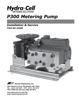
1.5 PRINCIPLE OF OPERATION
Pumping action is developed and controlled by four
basic components as follows (Figures 1 & 2):
1. The pump plunger “A” reciprocates with a
constant stroke length and displaces oil into and
out of the diaphragm chamber “C”.
2. The flexible diaphragm “X” is a movable partition
between the plunger oil and fluid being pumped.
3. An oil bypass circuit from the diaphragm
chamber “C” to the reservoir “D” through
passage “E” bypass port “H” and control spool
(valve) “F.”
4. A bypass control plunger “G” which moves with
and is directly coupled to the pump plunger to
correlate bypass shut off at port “H” to pump
plunger position.
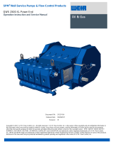
In operation, as the pump plunger and bypass control
plunger move forward as shown in Figure 1, the dis-
placed oil is bypassed to the oil reservoir until the con-
trol plunger “G” closes the bypass port “H” as shown in
Figure 2. Then the balance of the plunger displacement
is imposed on the flexible diaphragm that moves and
displaces the fluid being pumped through the dis-
charge ball checks.
On the suction stroke, the pump plunger pulls oil out of
the diaphragm cavity, which moves the flexible dia-
phragm and pulls fluid through the suction ball checks.
When the control plunger “G” opens the bypass port
“H” the balance of the plunger oil displacement can be
supplied from the reservoir through the bypass pas-
sages.

2
The discharge capacity is adjusted from 0–100% by
rotating the adjustment knob that moves the control
spool (valve) “F” so that the bypass port “H” is closed at
the desired percentage of the total plunger stroke.
When the control spool (valve) is adjusted to 100%
capacity the bypass port will be positioned so that it is
opened at the very end of the suction stroke. Then on
the pressure stroke, the bypass port is immediately
closed so the entire plunger displacement is imposed
upon the flexible diaphragm.
With the control spool (valve) adjusted for 50% capac-
ity the bypass port will be positioned so that it is
opened when the plungers have completed one-half of
the suction stroke. On the next pressure stroke, the oil
displaced by the pump plunger will be bypassed
through the open port to the reservoir for the first 50%
of the stroke before the by-pass port is closed by the
control plunger. The remaining 50% of the plunger dis-
placement will then be imposed on the flexible dia-
phragm so that fluid is discharged for only 50% of the
plunger travel. A similar analysis would apply for 0%
capacity setting on the control spool (valve) where all
the plunger oil displacement is bypassed to the reser-
voir.
Figure 1. Pump Operation With By-Pass Port Open
Figure 2. Pump Operation With By-Pass Port Closed

3
1.6 GENERAL SPECIFICATIONS
Accuracy
±1% steady state accuracy over 10:1 turndown
Drive
Hydraulic bypass design allows adjustment from
0 to 100% of rated capacity while stopped or
running
Liquid End
High performance check valves
Diaphragm
Hydraulically actuated diaphragm provides extra
long diaphragm life
Relief Valve
Adjustable internal relief valve
Capacity Control
Micrometer ..........................................standard
Electronic ................4–20 mA (except L series)
Pneumatic ................3–15 psi (except L series)
Stroke Length
Models RA, RH, RJ, RL, RP ...... 0.7” (1.78 cm)
Models RB, RM, RS ................... 1.5” (3.81 cm)
Figure 3. mRoy Data Plate

4
MODEL CODE SELECTION
END ITEM AND OPTION SELECT NUMBER
mROY A SERIES
R
A
1*
—
Material
Code
* 2 for Duplex
mRoy A LIQUID END MATERIAL CODE SELECTION
Code Description
0Cast Iron
1316 SS (STANDARD)
2 PVC (N/A with 9.5:1 Gear Ratio)
7 PVDF (N/A with 9.5:1 Gear Ratio)
5
A
lloy 20
6
A
lloy C22
mRoy A PLUNGER DIAMETER
Code Description
07 7/16" Diameter
10 5/8" Diameter
17 1-1/16" Diameter
mROY H SERIES
RH1 -
Material
Code
mRoy H LIQUID END MATERIAL
Code Description
0Cast Iron
1316 SS (STANDARD)
5
A
lloy 20
mRoy J SERIES
RJ1 -
Material
Code
mRoy J LIQUID END MATERIAL
Code Description
1316 SS (STANDARD)
5
A
lloy 20
mRoy P SERIES
RP1 -
Material
Code
mRoy P LIQUID END MATERIAL
Code Description
0Cast Iron
1316 SS (STANDARD)
5
A
lloy 20
mRoy P PLUNGER DIAMETER
Code Description
07 7/16" Diameter
10 5/8" Diameter
17 1-1/16" Diameter
& Base
Discharge Capacity Rupture
Diamete
r
Set Moto
r
Connection Connection Control Detection
Plunge
r
Gea
r
Mount / Suction
Control Detection
& Base
End item Model Code Option Select Number
Set Moto
r
Connection Connection
End Item Model Code Option Select Number
Gea
r
Mount / Suction Discharge Capacity Rupture
Control
Gea
r
Mount /
Set Moto
r
Connection Connection
Suction Discharge Capacity Base
Control Detection
& Base
End Item Model Code Option Select Number
Diameter Set Motor Connection
End item Model Code Option Select Number
Plunger Gear Mount / Suction Discharge Capacity Rupture
Figure 4. mRoy A, H, J, and P Model Code

5
GEAR SET (ALL mRoy A FRAME)
Code Description
77 77:1 Gear Ratio N/A for RJ or RP 23 spm 19 spm 15 spm
48 48:1 Gear Ratio
24 24:1 Gear Ratio
15 15:1 Gear Ratio
10 9.5:1 Gear Ratio N/A for RJ or RP
MOTORS and MOUNTS
STANDARD MOTOR with Close Coupled flan
g
e
Code Description
A
11/4 HP Motor, TE, 1725 RPM, 1 Phase, 60 Hertz, 115 Volt & Close Coupled Flan
g
e
A
81/4 HP Motor, TE, 1725 RPM, 3 Phase, 60 Hertz, 230/460 Volt & Close Coupled Flan
g
e
Note: These motors replace the obsolete inte
g
ral motor offerin
g
. They are standard
NEMA 56 C frame motor on a short flan
g
e.
MOTOR MOUNTS (Use only when motor is ordered from Milton Roy
1/4 HP minimum. Code Description
SR Close Coupled Flan
g
e, NEMA 56C (STANDARD)
SS Close Coupled Flan
g
e, IEC Frame 71, B5 Flan
g
e
FR
A
PI Flan
g
e Mount, NEMA 56C
F4
A
PI Flan
g
e Mount, NEMA 143TC/145TC
FS
A
PI Flan
g
e Mount, IEC Frame 71, B5 Flan
g
e
MD
A
PI Flan
g
e Mount, IEC Frame 80, B5 Flan
g
e
MOTOR MOUNTS
NOTE: Must be used when pump is not ordered with motor
1/4 HP minimum. Code Description
1X Close Coupled Flan
g
e, NEMA 56C
2X Close Coupled Flan
g
e, IEC Frame 71, B5 Flan
g
e
3X
A
PI Flan
g
e Mount, NEMA 56C
4X
A
PI Flan
g
e Mount, NEMA 143TC/145TC
5X
A
PI Flan
g
e Mount, IEC Frame 71, B5 Flan
g
e
6X
A
PI Flan
g
e Mount, IEC Frame 80, B5 Flan
g
e
SUCTION CONNECTION
Metallic Liquid Ends PVC 316 SS
A
lloy 20
Code Description
SE NPT 1/2" Female(STANDARD) N/
A
Standard
T
1
A
NSI 150# RF 1/2" Threaded N/
A
T
3
A
NSI 300# RF 1/2" Threaded N/
A
S1
A
NSI 150# RF 1/2" Socket Welded N/
A
S3
A
NSI 300# RF 1/2" Socket Welded N/
A
Plastic Liquid Ends
Code Description
SE NPT 1/2" Male (STANDARD) N/
A
T
1 150# 1/2" Thd flan
g
eN/
A
Notes:
1. Base option recommended with flan
g
ed connections.
2. Flan
g
es can only be welded at flan
g
ed end
DISCHARGE CONNECTION
Codes and prices are the same as Suction Connection.
Dischar
g
e connection size for SE code on metallic liquid ends is 1/4" NPT.
CAPACITY CONTROL
Code Description
M2 Manual Micrometer Knob - PVC(STANDARD)
M1 Manual Micrometer Knob - 316 SS
ML Lockin
g
Manual Micrometer Knob - 316 SS
E1 Electronic - NEMA 4, 4-20 mA, 115 Volt
E2 Electronic - NEMA 4, 4-20 mA, 220 Volt
EA Electronic - Explosion Proof, 4-20 mA, 115 Volt
EB Electronic - Explosion Proof, 4-20 mA, 220 Volt
EE Mount for Electronic, Less Actuator
PN Pneumatic, 3-15 psi, Direct Actin
g
N/
A
Standard N/
A
Standard
Does not require motor
mount from below
Motor supplied by Milton
Roy from Accessory
Section
Motor supplied by others
117 spm 96 spm 76 spm
185 spm 152 spm 120 spm
37 spm 30 spm 24 spm
73 spm 60 spm 47 spm
1725 rpm 1425 rpm 1140 rpm
Figure 5. mRoy A, H, J, and P Gear/Motor Mount/Connection/Capacity Control; Select Mode Code

6
Figure 6. mRoy A, H, J, and P Type of Liquid End; Select Mode Code
ROUTINE MAINTENANCE KITS mRoy A
Figure 7. mRoy A, H, J, L, and P Routine Maintenance Kit List, By Model Code
RUPTURE DETECTION & BASE (mRoy A FRAME)
Metallic Liquid Ends
Code Description
NN None (STANDARD)
NB Base Only - Recommended with Flanges
C5 Rupture Detection with Base & Gauge N/A on RH
SN Rupt. Detect. w/ Base, Gauge, & NEMA 4 Switch N/A on RH
S7 Rupt. Detect. w/ Base, Gauge, & Ex. Prf Switch N/A on RH
DD Double Diaphragm with Base N/A on RH or RJ
DP Double Diaphragm with Base & Conductivity Probe
Relay supplied separately - see accessory pricing
Plastic Liquid Ends
Code Description
NB Base Only (STANDARD)
DD Double Diaphragm with Base
DP Double Diaphragm with Base & Conductivity Probe
Relay supplied separately - see accessory pricing
MRoy RPM kits for pumps noted above
Model Liquid End Material Kit Number
MRoy A, H, J, L
316 SS & Cast Iron RPM002
Alloy 20 RPM005
PVC w/NPT connections RPM007
PVC w/tubing connections RPM003
PVDF w/NPT connections RPM008
PVDF w/tubing connections RPM004
Alloy C22 RPM006
RA11 w/Peek Diaph., 5 inch RPM087
Hast B RPM093
Diaph Teflon, 3.98 inch RPM0013037
MRoy P 316 ss & Cast Iron RPM009
Alloy 20 RPM010

7
MODEL RA CAPACITY/PRESSURE TABLE
Plgr.
Dia. Gear
Code
SPM 60 hz
50 hz
Metallic Plastic
100 PSI 150 PSI 200 PSI 300 PSI 350 PSI 100 PSI 150 PSI
7/16”
77 23
(19)
0.57
(0.47)
0.57
(0.47)
0.56
(0.46)
0.55
(0.46)
0.55
(0.46)
0.48
(0.40)
0.46
(0.38)
48 37
(30)
0.8
(0.66)
0.7
(0.58)
0.7
(0.58)
0.7
(0.58)
0.7
(0.58)
0.65
(0.54)
0.62
(0.51)
24 73
(60)
1.7
(1.41)
1.7
(1.41)
1.7
(1.41)
1.6
(1.33)
1.6
(1.33)
1.5
(1.25)
1.5
(1.25)
15 117
(96)
2.8
(2.32)
2.7
(2.24)
2.7
(2.24)
2.7
(2.24)
2.6
(2.16)
2.5
(2.08)
2.4
(1.99)
5/8”
48 37
(30)
1.8
(1.49)
1.7
(1.41)
1.7
(1.41)
1.6
(1.33)
1.6
(1.33)
1.6
(1.33)
1.5
(1.25)
24 73
(60)
3.8
(3.15)
3.7
(3.07
3.7
(3.07
3.6
(2.99)
3.5
(2.90)
3.5
(2.90)
3.4
(2.82)
15 117
(96)
6.2
(5.15)
6.1
(5.06)
6.0
(4.98)
5.9
(4.90)
5.7
(4.73)
5.6
(4.65)
5.5
(4.57)
1-1/16”
48 37
(30)
6.1
(5.06)
6.0
(4.98)
5.9
(4.90)
5.7
(4.73)
5.5
(4.57)
5.7
(4.73)
5.6
(4.65)
24 73
(60)
12.3
(10.21)
12.2
(10.13)
12.1
(10.04)
11.5
(9.55)
11.2
(9.30)
11.3
(9.38)
11.2
(9.30)
15 117
(96)
117
(96)
19.4
(16.10)
19.3
(16.02)
18.5
(15.35)
18.1
(15.02)
18.1
(15.02)
18.0
(14.94)
10 185
(152
30.0
(24.90)
29.5
(24.48)
29.0
(24.07)
--
--
--
--
--
--
--
--
NOTES: Refer to notes shown in Figure 10, mRoy B Capacity/Pressure Table.
Figure 8. mRoy A Capacity/Pressure Table (capacities shown in GPH)
MODEL RP CAPACITY/PRESSURE TABLE
Plgr.
Dia.
Gear
Code
SPM 60 hz
(50 hz)
Metallic Only Max. Fluid Viscosity
(Centipoise)
100 PSI 150 PSI 200 PSI 300 PSI 350 PSI
7/16”
77 23
(19)
0.51
(0.42)
0.51
(0.42)
0.50
(0.41)
0.49
(0.41)
0.49
(0.41)
12,200
48 37
(30)
0.72
(0.60)
0.63
(0.52)
0.63
(0.52)
0.63
(0.52)
0.63
(0.52)
7,500
24 73
(60)
1.5
(1.25)
1.5
(1.25)
1.5
(1.25)
1.4
(1.16)
1.4
(1.16)
4,000
15 117
(96)
2.5
(2.08)
2.4
(1.99)
2.4
(1.99)
2.4
(1.99)
2.3
(1.91)
2,000
5/8”
48 37
(30)
1.6
(1.33)
1.5
(1.25)
1.5
(1.25)
1.4
(1.16)
1.4
(1.16)
5,000
24 73
(60)
3.4
(2.82)
3.3
(2.74)
3.3
(2.74)
3.2
(2,66)
3.1
(2.57)
2,500
15 117
(96)
5.6
(4.65)
5.5
(4.57)
5.4
(4.48)
5.3
(4.40)
5.1
(4.23)
1,250
1 1/16”
48 37
(30)
5.5
(4.57)
5.4
(4.48)
5.3
(4.40)
5.1
(4.23)
4.9
(4.07)
1,000
24 73
(60)
11.0
(60)
10.9
(9.05)
10.8
(8.96)
10.2
(8.47)
9.9
(8.22)
500
15 117
(96)
17.5
(14.52)
17.4
(14.44)
17.3
(14.36)
16.6
(13.78)
16.2
13.45)
300
NOTES: Refer to notes shown in Figure 10, mRoy B Capacity/Pressure Table
Figure 9. mRoy P Capacity/Pressure Table (capacities shown in GPH)

8
NOTES:
1. Capacities shown are for simplex pumps. Double capacity for duplex pumps.
2. Certain options require that the maximum capacity be derated. Refer to the derating table.
3. Capacities shown are the max. pump capacities in gph, based on 60 hz, 1725 rpm. 50 hz, 1425 max. capacities are
shown in ().
4. Non-shaded ranges require ½ hp 3 phase of ¾ hp single phase motors. Shaded Ranges require ¾ hp 3 phase or
1 hp single phase motors.
* Duplex 1 7/16” plungers at 96 or 144 SPM are limited to 250 psi.
** Duplex 1 7/16” plungers at 96 or 144 SPM are limited to 250 psi.
PVC is limited to 150 psi. PVC is not available on pumps with a 19/32” plunger
Figure 10. mRoy B Capacity/Pressure Table (capacities shown in GPH)
MODEL RB, RM, RS CAPACITY PRESSURE TABLE
MODEL SPM
PVC & Metallic Metallic Only
100 PSI 150 PSI 200 PSI 400 PSI 600 PSI 800 PSI 1000 PSI 1200 PSI 1500 PSI
RS
19/32”
Dia.
48
(40)
4.7
(3.90)
4.6
(3.82)
4.6
(3.82)
4.4
(3.65)
4.2
(3.49)
4.0
(3.32)
3.8
(3.15)
3.6
(2.99)
3.3
(2.74)
72
(60)
7.0
(5.81)
6.9
(5.73)
6.9
(5.73)
6.7
(5.56)
6.5
(5.39)
6.3
(5.23)
6.1
(5.06)
5.9
(4.90)
5.6
(4.65)
96
(80)
9.5
(7.88)
9.4
(7.80)
9.3
(7.72)
8.9
(7.39)
8.6
(7.14)
8.3
(6.89)
7.9
(6.56)
7.6
(6.31)
7.1
(5.89)
144
(120)
13.3
(11.04)
13.2
(10.96)
13.1
(10.87)
12.8
(10.62)
12.5
(10.38)
12.3
(10.21)
12.0
(9.96)
11.8
(9.79)
11.4
(9.46)
RM
7/8”
Dia.
48
(40)
10.0
(8.30)
9.7
(7.80)
9.4
(7.80)
8.2
(6.81)
7.0
(5.81)
5.9
(4.90)
4.7
(3.90)
72
(60)
16.0
(13.28)
15.7
(13.03)
15.4
(12.78)
14.3
(11.87)
13.2
(10.96)
12.1
(10.04)
11.0
(9.13)
96
(80)
21.0
(17.43)
20.7
(17.18)
20.4
(16.93)
19.3
(16.02)
18.2
(15.11)
17.1
(14.19
16.0
(13.28)
144
(120)
30.4
(25.23)
30.1
(24.98)
29.9
(24.82)
28.9
(23.99)
27.9
(23.16)
27.0
(22.41)
25.6
(21.25)
RB
1-7/16”
Dia.
48*
(40)*
27.0
(22.41)
26.0
(21.58)
25.0
(20.75)
21.0
(17.43)
72*
(60)*
42.0
(34.86)
41.0
(34.03)
40.0
(33.20)
36.0
(29.88)
96**
(80)**
57.0
(47.31)
56.0
(46.48)
55.0
(46.65)
51.0
(42.33)
144**
(120)**
85.0
(70.55)
84.0
(69.72)
83.0
(68.89)
79.0
(65.57)
MROY PUMP FLOW DERATING TABLE
Plunger Diameter 7/16” & 5/8” 1 1/16” 19/32” 7/8” 1 716”
Series LAHPLAPBBB
Electronic or Pneumatic
Capacity Control
-- 0.95 0.95 0.95 -- 0.90 0.90 1.0 0.90 0.90
Diaphragm Rupture
Detection
-- 0.95 -- 0.95 -- 0.95 0.95 0.95 0.95 0.95
Double Diaphragm 0.95 0.95 -- 0.95 0.95 0.95 0.95 0.95 0.95 0.95
NOTES:
Certain options require that the maximum capacity be derated. Multiply capacities in the capacity/pressure tables in Figures 7 through 10
by the appropriate factors in the table above.
Figure 11. mRoy Pump (All Models) Capacity Derating Table

9
Figure 12. mRoy B Model Codes
mRoy B Series MODEL CODE SELECTION
END ITEM AND OPTION SELECT NUMBER
End item Model Code Option Select Number
R
1* -
Plun
g
er Liquid End Gear Motor Suction Dischar
g
e Capacity Rupture
Diameter Material Set Mount Connection Connection Control Detection
* 2 for Duplex & Base
PLUNGER DIAMETE
R
Code Description
S 19/32" Diameter
M 7/8" Diameter
B1-7/16" Diameter
LI
Q
UID END MATERIAL Code Description
1316 SS (STANDARD)
2 PVC (not available with plun
g
er code "S")
5
A
lloy 20
7PVDF(Plun
g
er code "B" only)
GEAR SET Code Description 1725 rpm 1425 rpm 1140 rpm
38 38:1 Gear Ratio 48 spm 40 spm 31 spm
25 25:1 Gear Ratio 72 spm 60 spm 48 spm
19 19:1 Gear Ratio 96 spm 80 spm 62 spm
12 12:1 Gear Ratio 144 spm 120 spm 95 spm
10 9.51 Gear Ratio 148 spm N/A
MOTOR MOUNTS
MOTOR MOUNTS (Use only when motor is ordered from Milton Roy - see section 4100)
Refer to Capacity/Pressure table for horsepower required.
Code Description
FR
A
PI Flan
g
e Mount, NEMA 56C
F4
A
PI Flan
g
e Mount, NEMA 143TC/145TC
F8
A
PI Flan
g
e Mount, IEC Frame 80, B5 Flan
g
e
F9
A
PI Flan
g
e Mount, IEC Frame 90, B5 Flan
g
e
MOTOR MOUNTS
NOTE: Must be used when pump is not ordered with motor (to cover added cost of testin
g
).
Refer to Capacity/Pressure table for horsepower required.
Code Description
3X
A
PI Flan
g
e Mount, NEMA 56C
4X
A
PI Flan
g
e Mount, NEMA 143TC/145TC
5X
A
PI Flan
g
e Mount, IEC Frame 80, B5 Flan
g
e
6X
A
PI Flan
g
e Mount, IEC Frame 90, B5 Flan
g
e
SUCTION CONNECTION PVC 316 SS
A
lloy 20
Metallic Liquid Ends Code Description
SE NPT 1/2" Female (STANDARD) N/
A
Standard Standard
T
1
A
NSI 150# RF 1/2" Threaded N/
A
T
3
A
NSI 300# RF 1/2" Threaded N/
A
S1
A
NSI 150# RF 1/2" Socket Welded N/
A
S3
A
NSI 300# RF 1/2" Socket Welded N/
A
Plastic Liquid End SE NPT 1/2" Male (STANDARD) Standard N/A N/A
T
1 150# 1/2" Thd flan
g
eN/AN/A
Notes: 1. Base option recommended with flan
g
ed connections. 2. Flan
g
es can only be welded at flan
g
ed end.
DISCHARGE CONNECTION Same codes and prices as Suction Connection
NOTE: Connection sizes for SE code metallic are 3/8" NPT on RM & RB series, and 1/4" NPT on RS series.
Motor supplied by others
Motor supplied by Milton Roy
from Accessory Section
N/
A
CAPACITY CONTROL Code Description
A
LManual Micrometer Knob - Aluminum (STANDARD)
ML Manual Micrometer Lockin
g
Knob - 316 SS
E1 Electronic - NEMA 4, 4-20 mA, 115 Volt Remember to derate pump
E2 Electronic - NEMA 4, 4-20 mA, 220 Volt Remember to derate pump
E
A
Electronic - Explosion Proof, 4-20 mA, 115 Volt Remember to derate pump
EB Electronic - Explosion Proof, 4-20 mA, 220 Volt Remember to derate pump
EE Mount for Electronic, Less Actuator
PN Pneumatic, 3-15 psi, Direct Actin
g
Remember to derate pump
RUPTURE DETECTION & BASE
A
ll Liquid Ends Code Description
NN None (STANDARD) Standard
NB Base
Metallic Liquid Code Description
Ends Only C5 Rupture Detection with & Gau
g
eRemember to derate pump
SN Rupt. Detect. W/Gau
g
e, & NEMA 4 Switch Remember to derate pump
S7 Rupt.Detect. W/Gau
g
e, & Exp. Prf Switch Remember to derate pump
Plastic Liquid DD Double Diaphra
g
mRemember to derate
End Only DP Double Diaphra
g
m w/Conductivity Probe Remember to derate
Relay supplied separately - see accessory pricin
g

10
Figure 13. mRoy B Routine Maintenance Kit List, By Model Code
ROUTINE MAINTENANCE KITS mRoy B
MRoy RPM kits for pumps noted above
Model Liquid End Material Kit Number
MRoy S
316 ss RPM011
Alloy 20 RPM012
RS 11 w/Peek Diaph. RPM092
MRoy M & B 316 ss RPM-0014-021
PVC RPM-0014-032
Alloy 20 RPM-0014-025
RB Kynar RPM-0014-037

11
SECTION 2
INSTALLATION
2.1 UNPACKING/INSPECTION
Units are shipped Ex Works, Ivyland, Pa. and the title
passes to the customer when the carrier signs for
receipt of the unit. In the event that damages occur dur-
ing shipment, it is the responsibility of the customer to
notify the carrier immediately and to file a damage
claim. Carefully examine the shipping crate upon
receipt from the carrier to be sure there is no obvious
damage to the contents. Open the crate carefully so
accessory items fastened to the inside of the crate will
not be damaged or lost. Examine all material inside the
crate and check against the packing list to be sure that
all items are accounted for and intact.
2.2 SAFETY PRECAUTIONS
When installing, operating, and maintaining the mRoy
pump, keep safety considerations foremost. Use
proper tools, protective clothing, and eye protection
when working on the equipment and install the equip-
ment with a view toward ensuring safe operation. Fol-
low the instructions in this manual and take additional
safety measures appropriate to the liquid being
pumped. Be extremely careful in the presence of haz-
ardous substances (e.g., corrosives, toxics, solvents,
acids, caustics, flammables, etc.).
2.3 PUMP MOUNTING/LOCATION
The mRoy pump can be mounted on any surface that
is flat and level for the support feet. Three mounting
bolt holes are provided in the support feet for use when
the pump is to be firmly anchored to a base surface
(see Figure 14.)
Increased reliability can be expected if pump locations
are avoided which are subjected to high ambient tem-
peratures above 100°F (38°C) with poor free-air circu-
lation over the pump assembly.
2.4 OUTDOOR INSTALLATIONS
The mRoy pump is designed as a totally enclosed unit
suitable for installation either indoors or outdoors. How-
ever, for outdoor installations the pump mounting area
should be selected to provide protection against envi-
ronmental extremes:
1. Operation with continuous exposure to tropical or
subtropical sunshine with ambient temperatures
above 90°F (32°C), which would cause higher oil
temperatures and affect lubricity should be
avoided. Good installation practice would dictate
providing a sun shade cover over the pump with
open sides to obtain the best air circulation
around the pump.
2. Frequent start-up where the pump has been idle
in an ambient temperature below 30°F (-1°C) is
not recommended. Provide a removable,
insulated enclosure over the pump and mounting
base with provisions for an electrical heater (100
watt light, heat lamp, heater tape etc.) to
maintain the pump oil temperature above 30°F (-
1°C).
2.5 FLANGE MOUNTED MOTORS
If a flange mounted motor option was selected for the
mRoy pump, the customer supplied motor will need to
be mounted to the pump. This is generally a straight
forward procedure. Refer to Figure 18 or 19, as appro-
priate.
When mounting the motor to a NEMA 56C Close Cou-
pled Flange (product code option SR, refer to Figure
19), the motor mount plate (710) must be removed
from the pump body and bolted to the motor. The
motor/motor mount plate assembly can then be bolted
to the pump.
2.6 ELECTRICAL CONNECTIONS
Check to be sure that the electrical supply matches the
pump motor nameplate electrical characteristics. Motor
rotation must be counter clockwise when viewed from
the top end of the motor.
ON SINGLE-PHASE PUMP MOTORS THE
ROTATION WILL BE DETERMINED AT THE
FACTORY AND MUST NOT BE CHANGED.
ON THREE-PHASE PUMP MOTORS THE
ROTATION MUST BE DETERMINED AT THE
TIME OF INSTALLATION AND PRIOR TO
START-UP. OPERATION WITH THE
WRONG ROTATION WILL DAMAGE THE
PUMP AND MOTOR AND VOID THE WAR-
RANTY. SHAFT ROTATION CAN BE
OBSERVED BY REMOVING THE COVER
PLATE OVER THE ELECTRICAL CONNEC-
TIONS.

12
2.7 MOTORS
Adequate power is provided to the simplex mRoy A
pump by the standard ¼ HP (0.2 Kw) motor. The motor
is normally a totally enclosed non-ventilated, type, that
is mounted on a 56C-face flange or IEC Frame 71
flange. The gear reducer (worm shaft) fits onto the
standard motor without using a coupling.
On the larger mRoy B (Figures 10-13), the normal tem-
perature rise for these motors is 50°C above ambient
temperature, and it can be expected that these motors
will appear to operate at higher temperatures than are
normally experienced. However, there is no cause for
worry if the following precautions are observed:
1. The motor is placed where there is adequate
ventilation and is protected against excessive
radiation from steam pipes and other heat
sources.
2. The overload heater in the starting device should
be correctly sized for motor full load current
rating as shown on the motor data plate.
2.8 PUMP LUBRICATION
Oil is supplied for the average installation (ambient
temperature above 50°F (10°C). See recommendation
below for lower temperature. Fill pump and gear box by
slowly pouring the proper oil through the air bleed res-
ervoir opening until the oil level in the reservoir is level
with oil level mark on outside surface of reservoir. Level
can also be checked with dipstick on oil reservoir cap.
Recheck while pump is operating.
DO NOT OVER FILL AS MOTOR DAMAGE
CAN RESULT.
NOTE: Synthetic oils are available that span the
entire temperature range. Contact Milton Roy for
further information.
Recommended Oil
Any equivalent oil is acceptable.
Nominal Oil Capacity
2.9 PIPING
General
Refer to Figure 16 for a diagram of a typical recom-
mended piping system.
Support all piping connections to the pump so that no
stress is placed on pump fittings. In no case should the
piping be sprung to make the connections to the pump.
The suction and discharge cartridge pipe connections
can be positioned within an arc of approximately 150°
to facilitate piping to pump.
Oil Type Ambient
Temp. 15-50 °F
(-9-10 °C)
Ambient
Temp. Above 50°F
(10 °C)
AGMA Spec No. 2 EP No. 5 EP
Zurn Oil Co No. EP 35 No. EP 95
ISO Grade 68 220
Pump Model Simplex Duplex
mRoy A 1 Qt.
(.95 liters)
2 Qts.
(1.9 liters)
mRoy B 3 Qts.
(2.8 liters)
4 Qts.
(3.8 liters)
Figure 14. Mounting Bolt Holes

13
Flush and blow out all pipelines before connecting the
pump. This eliminates any foreign matter that might
seriously damage the internal working parts of the liq-
uid end. Install a 20 mesh Y-type strainer that is sized
to remove foreign particles with minimum pressure
drop in the suction line of the pump.
Install shut-off valves, with unions on the pump side of
the valves, in the suction and discharge lines to facili-
tate servicing.
Use extreme care in piping to plastic liquid end pumps
with rigid pipe such as PVC. If excessive stresses or
vibration is unavoidable, flexible connections are rec-
ommended.
NOTE: Many pipe joint compounds are not suit-
able for use with plastic pipe and, if used, will
cause stress cracking at the connection. Use only
compounds commended for use with plastic mate-
rials.
Suction Piping
The suction piping must be absolutely tight and leak-
free. For mRoy pumps on water-like solutions we rec-
ommend that the suction pipe be ¾” minimum diameter
and a maximum of 6 feet (2 meters) long. The intent is
that the piping must be designed to provide an ade-
quate net positive suction head (NPSH). Obtain our
NPSH Calculation software at the Milton Roy Web site
(miltonroy.com). If assistance in determining NPSH is
needed, contact the Milton Roy Aftermarket Service
department.
A flooded suction is recommended for optimum service
life and maintenance-free operation. However, the
mRoy pump can operate with less than flooded suction
if necessary, in accordance with the following schedule
shown in the chart below.
Refer to “Installation with Suction Lift,” which outlines
limiting conditions if suction lift requirements are antici-
pated.
The supply tank should incorporate a low-level switch
to cut off the pump motor circuit before the suction
intake is exposed to air. Otherwise, the pump may
occasionally run dry.
Discharge Piping
The installation of an external Safety Valve is recom-
mended, since the pump’s internal relief valve is not in-
tended to protect the piping system. Refer to “Setting
the Relief Valve” in Section 3, for further relief valve
discussion. (Milton Roy offers a complete line of back
pressure and safety valves).
For satisfactory metering and capacity control, the dis-
charge pressure at the pump must be 50 PSIG (3.5
Bar) Minimum for the mRoy A and 70 PSIG (4.8 Bar)
minimum for the mRoy B. Therefore, when the pump is
to discharge into an open system, a back pressure
device must be installed in the pump discharge car-
tridge or line. (except the mRoy A plastic design).
Installation of this spring will assure repetitive metering
accuracy.
A spring (1390) is attached to each pump (Metallic Liq-
uid End) in a small cloth bag (1380) for installation in
the discharge cartridge to develop the required back
pressure on the pump if a separate back pressure
valve is not used (mRoy A Figure 15 and 21, mRoy B
Figure 25). The back pressure spring should slip easily
through the hole in the seat. Do not disassemble the
seat and/or ball from metallic check valves. These
check valves are precision manufactured at Milton Roy
and should not be disassembled in the field.
Figure 15. Back Pressure Spring Installation
Model
Number
Min. NPSH
(PSIA)
Max. Lift
(Ft. (meter)
H2O)
mRoy A RA 10 10 (3)
mRoy H RH 10 10 (3)
mRoy P RP 10 10 (3)
mRoy B
RS 10 5 (1.5)
RM 10 5 (1.5)
RB 10 2 (.6)
2.10 BACK PRESSURE SPRING INSTALLATION

14
The plastic liquid end mRoy B pumps (Figure 25) al-
ways use a back pressure spring in the discharge car-
tridge, so retrofitting the back pressure spring into the
discharge is not required on these pumps.
AFTER PUMP HAS BEEN FULLY PRIMED,
REMOVE THE CAP FROM THE BODY AND
INSERT SPRING THROUGH THE TOP SEAT
TO REST ON TOP OF THE BALL CHECK.
REPLACE CAP AND TIGHTEN UNTIL
FIRMLY SEATED ON BODY. DO NOT OVER-
TIGHTEN, AS O-RING PROVIDES THE
SEAL.
REMOTE HEAD SYSTEMS: DO NOT
INSTALL A BACK PRESSURE SPRING IN
THE DISCHARGE BALL CHECK CAR-
TRIDGE OF DIAPHRAGM HEADS WHICH
ARE “REMOTE MOUNTED” (NOT
ATTACHED TO THE MAIN HOUSING). A
SEPARATE BACK PRESSURE VALVE
MUST BE INSTALLED IN THE DISCHARGE
LINE FROM THE REMOTE HEAD CAR-
TRIDGE.
TAKE CARE WHEN INSERTING THE DIS-
CHARGE PIPE NIPPLE INTO THE BALL
CHECK CARTRIDGE. NIPPLE SHOULD
NOT EXTEND INTO CAVITY, CAUSING
CLAMPING OF THE SPRING AND RETARD-
ING NORMAL OPERATION.
Figure 16. Typical Piping System Installation
Page is loading ...
Page is loading ...
Page is loading ...
Page is loading ...
Page is loading ...
Page is loading ...
Page is loading ...
Page is loading ...
Page is loading ...
Page is loading ...
Page is loading ...
Page is loading ...
Page is loading ...
Page is loading ...
Page is loading ...
Page is loading ...
Page is loading ...
Page is loading ...
Page is loading ...
Page is loading ...
Page is loading ...
Page is loading ...
Page is loading ...
Page is loading ...
Page is loading ...
Page is loading ...
Page is loading ...
Page is loading ...
Page is loading ...
Page is loading ...
Page is loading ...
Page is loading ...
Page is loading ...
Page is loading ...
Page is loading ...
Page is loading ...
Page is loading ...
Page is loading ...
Page is loading ...
Page is loading ...
Page is loading ...
Page is loading ...
Page is loading ...
Page is loading ...
Page is loading ...
Page is loading ...
Page is loading ...
Page is loading ...
Page is loading ...
Page is loading ...
Page is loading ...
Page is loading ...
-
 1
1
-
 2
2
-
 3
3
-
 4
4
-
 5
5
-
 6
6
-
 7
7
-
 8
8
-
 9
9
-
 10
10
-
 11
11
-
 12
12
-
 13
13
-
 14
14
-
 15
15
-
 16
16
-
 17
17
-
 18
18
-
 19
19
-
 20
20
-
 21
21
-
 22
22
-
 23
23
-
 24
24
-
 25
25
-
 26
26
-
 27
27
-
 28
28
-
 29
29
-
 30
30
-
 31
31
-
 32
32
-
 33
33
-
 34
34
-
 35
35
-
 36
36
-
 37
37
-
 38
38
-
 39
39
-
 40
40
-
 41
41
-
 42
42
-
 43
43
-
 44
44
-
 45
45
-
 46
46
-
 47
47
-
 48
48
-
 49
49
-
 50
50
-
 51
51
-
 52
52
-
 53
53
-
 54
54
-
 55
55
-
 56
56
-
 57
57
-
 58
58
-
 59
59
-
 60
60
-
 61
61
-
 62
62
-
 63
63
-
 64
64
-
 65
65
-
 66
66
-
 67
67
-
 68
68
-
 69
69
-
 70
70
-
 71
71
-
 72
72


Milton Roy mRoy B Installation, Operation and Maintenance Manual
- Type
- Installation, Operation and Maintenance Manual
Ask a question and I''ll find the answer in the document
Finding information in a document is now easier with AI
Other documents
-
ProMinent ProMus Series Operating Instructions Manual
-
 IWAKI LK-A User manual
-
LMI SD2287P Owner's manual
-
GGM Gastro KWFR User manual
-
LMI SG76P8P Owner's manual
-
 Hydra-Cell P300 Installation Service
-
 Weir SPM QWS 2500 XL Operation Instruction And Service Manual
-
Pulsafeeder Pulsa 7120 Owner's manual
-
Sandpiper S05B1ABWANS000 Owner's manual
-


