Page is loading ...

PB-SSTR
6/2023
Side-To-Side Tarp System
Models 8100 • 9100 • RT • RTX
Supplemental Manual
&
Parts Book

Meyer Manufacturing Corporation - 2 - PB-SSTR
1.0 IMPORTANT INFORMATION
This supplement document is to be used in addition to the standard Operator Manual that was shipped with
your implement along with the documents that Roll-Rite provides for their equipment.
Meyer Manufacturing Corporation
674 W. Business Cty Rd A
Dorchester, WI 54425
Phone: 1-800-325-9103
Fax: 715-654-5513
Email: [email protected]
Website: www.meyermfg.com


1-800-325-9103
PB-SSTR - 5 - www.meyermfg.com
3.0 INTRODUCTION
Congratulations on your purchase of a new Meyer farm equipment product. Undoubtedly you have given
much consideration to your purchase and we’re proud that you have selected Meyer. Pride in craftsmanship,
engineering and customer service have made Meyer products the finest in the farm equipment industry today.
There is no substitute for quality. That is why thousands of people like you have purchased Meyer farm
equipment. They felt it was the best equipment to serve their farming needs, now and in years to come. We
ask that you follow our policy of “safety first”, and we strongly suggest that you read through the “Owner /
Operator’s Manual & Parts Book” before operating your Meyer farm equipment. Meyer Manufacturing
Corporation wants to thank you for not compromising quality. We are determined to offer excellence in
customer service as well as provide you with the very best value for your dollar.
Sincerely,
All Employees of
MEYER MANUFACTURING CORPORATION
The information being provided, is not to supersede Roll-Rite’s® documents, but to be used in conjunction with
their documents.
See Roll-Rite’s® manuals for details and warnings. www.rollrite.com or call Roll-Rite at 1-800-297-9905
Manufacturer’s Statement: Meyer Manufacturing Corporation reserves the right to make improvements in
design, or changes in specifications at any time, without incurring any obligation to owners of units previously
sold. This supersedes all previous published instructions.
IMPORTANT: You are urged to study this manual and follow the instructions carefully. Your efforts
will be repaid in better operation and service as well as a savings in time and repair expense.
Failure to read this manual and understand the machine could lead to serious injury. If you do
not understand instructions in this manual, contact either your dealer or Meyer Manufacturing
Corporation in Dorchester, WI.
REPAIR PARTS: At the back of this manual is the repair parts section. All replacement parts are
to be obtained from, or ordered through, your Meyer dealership. When ordering repair parts,
refer to the parts section and give complete information including quantity, correct part number,
detailed description and even model number and serial number of the Implement which needs
repair parts.


1-800-325-9103
PB-SSTR - 9 - www.meyermfg.com
TABLE OF CONTENTS
1.0 IMPORTANT INFORMATION.....................................................................................................2
2.0 PRE-DELIVERY & DELIVERY CHECK LIST .............................................................................3
3.0 INTRODUCTION.........................................................................................................................5
4.0 MANUFACTURER’S WARRANTY .............................................................................................7
5.0 SAFETY....................................................................................................................................11
5.1 SAFETY PRECAUTIONS.................................................................................................12
5.2 SAFETY SIGNS................................................................................................................12
5.3 SHUTOFF & LOCKOUT POWER.....................................................................................13
5.3.1 SHUTOFF & LOCKOUT POWER PROCEDURE .................................................13
5.3.2 REMOVE AND ISOLATE THE SOURCE OF ELECTRICAL POWER ..................14
5.3.3 RELEASING STORED ENERGY ..........................................................................14
5.3.3.1 DISSIPATING STORED SPRING ENERGY PRIOR TO SERVICE........ 14
6.0 PRE-OPERATION ....................................................................................................................17
6.1 STATIC INSPECTION ......................................................................................................17
6.2 ELECTRICAL HOOK-UP..................................................................................................17
6.2.1 WIRING SCHEMATICS ........................................................................................18
6.2.1.1 9100 TRAILERS PRIOR TO SN 1391259............................................... 18
6.2.1.2 9100 TRAILERS SN 1391259 & LATER................................................. 19
6.3 START-UP AND SHUT-DOWN........................................................................................20
6.4 OPERATIONAL CHECKS.................................................................................................20
6.5 CONTROLS......................................................................................................................20
6.6 OPTIONAL EQUIPMENT..................................................................................................21
7.0 OPERATION.............................................................................................................................23
7.1 LOADING..........................................................................................................................23
8.0 MAINTENANCE........................................................................................................................25
8.1 LUBRICATION..................................................................................................................25
8.2 ADJUSTMENTS................................................................................................................26
8.2.1 TARP RETURN TENSION ....................................................................................26
8.2.2 TARP ADJUSTMENT ............................................................................................26
8.3 STORING AN IMPLEMENT WITH TARP SYSTEM.........................................................26
8.4 TROUBLESHOOTING......................................................................................................27
8.4.1 TARP SYSTEM CONTROL MODULE LED CODES ............................................27
8.4.2 TROUBLESHOOTING GUIDE ..............................................................................27

Meyer Manufacturing Corporation - 10 - PB-SSTR
TABLE OF CONTENTS
9.0 PARTS REPAIR AND REPLACEMENT ...................................................................................29
TARP COMPONENTS (8100 & 9100)......................................................................................30
SYSTEM, PASSENGER 3" AXLE & SPRING RETURN (RTX222 & RTX224 BODY).............32
ELECTRIC KIT WITH RELAY AND ROCKER SWITCH...........................................................34
6-SPRING TOP MOUNT PIVOT W/O TUBE (PASSENGER STOWAGE)...............................36
FRONT PIVOT ARM.................................................................................................................37
AXLE KIT...................................................................................................................................38
AXLE HARDWARE...................................................................................................................39
TARP RETURN.........................................................................................................................40
BOWS & MOUNTING COMPONENTS.....................................................................................41
10.0 MAINTENANCE RECORDS.....................................................................................................43

1-800-325-9103
PB-SSTR - 11 - www.meyermfg.com
5.0 SAFETY
The Meyer Implement is manufactured with operator safety in mind. Located on the implement are various
safety signs to aid in operation and warn of danger or caution areas. Pay close attention to all safety signs on
the implement.
Carefully follow the operating and maintenance instructions in this manual and all applicable safety laws.
Failure to follow all safety procedures may result in serious injury or death.
Before attempting to operate this implement, read and study the following safety information. In addition, make
sure that every individual who operates or works with the implement, whether family member or employee, is
familiar with these safety precautions.
Meyer Mfg. Corp. provides guards for exposed moving parts for the operator’s protection; however, some areas
cannot be guarded or shielded in order to assure proper operation. The operator’s manual and safety signs on
the implement itself warn you of dangers and must be read and observed closely!
!
Safety Alert Symbol This symbol is used to call attention to instructions
concerning personal safety. Be sure to observe and
follow these instructions. Take time to be careful!
The signal word DANGER on the machine and in the manual
identifies a hazardous situation which, if not avoided, WILL result
in death or serious injury.
!DANGER
The signal word WARNING on the machine and in the manual
indicates a potentially hazardous situation which, if not avoided,
COULD result in serious injury or death.
WARNING
!
The signal word CAUTION on the machine and in the manual
indicates a potentially hazardous situation which, if not avoided,
MAY result in minor or moderate injury. It may also be used to
alert against unsafe practices.
!
CAUTION
This notice identifies procedures which must be followed to avoid
damage to the machine.
IMPORTANT
Danger, Warning, Caution, and instructional decals and plates are placed on the equipment to protect anyone
working on or around this machine, as well as the components of the machine. All personnel operating or
maintaining this equipment must familiarize themselves with all Danger, Warning, Caution, and instructional
decals and plates.

Meyer Manufacturing Corporation - 12 - PB-SSTR
5.1 SAFETY PRECAUTIONS
All individuals who will operate this implement must read
and completely understand this Owner / Operator’s and Parts
Manual. Operator must receive instructions before operating
the machine. Untrained operators can cause injury or death.
!
CAUTION
• DO NOT allow anyone to operate, service, inspect or otherwise handle this implement until all operators
have read and understand all of the instructional materials in the Supplement and Parts Manual and have
been properly trained in its intended usage.
• Operator’s must not use drugs or alcohol which impair alertness or coordination while working. An operator
who is taking prescription drugs must get medical advice to determine if he or she can safely operate a
machine and the equipment.
• Make sure all personnel can READ and UNDERSTAND all safety signs.
• DO NOT allow minors (children) or inexperienced persons to operate this implement.
• DO NOT operate until all shields and guards are in place and securely fastened.
• DO NOT step up on any part of the implement at any time.
• DO NOT adjust, clean or lubricate while the implement is in motion.
• Inspect when first delivered and regularly thereafter; that all connections and bolts are tight and secure
before operating.
• Know how to stop operation of the implement before starting it!
• Make certain everyone is clear of the implement before applying power.
• Keep hands, feet and clothing away from moving parts. Loose or floppy clothing should not be worn by the
operator.
• Observe all applicable traffic laws when transporting on public roadways (where legal to do so). Check local
laws for all highway lighting and marking requirements.
• Shut off and lock out power before adjusting, servicing, maintaining or clearing an obstruction from this
machine. Refer to
5.2 SAFETY SIGNS
Read all safety signs on the implement and in this manual. Keep all
safety signs clean and replace any damaged or missing safety
signs before operating the equipment. Do not remove any safety
signs. Safety signs are for operator protection and information.
!
CAUTION
See Roll-Rite’s Side to Side Tarp Manual for all applicable safety signs.
Section 5.3 SHUTOFF & LOCKOUT POWER.
All individuals who will operate this implement must read and
completely understand this Supplement Manual. Operator
must receive instructions before operating the machine.
Untrained operators can cause injury or death.

1-800-325-9103
PB-SSTR - 13 - www.meyermfg.com
5.3 SHUTOFF & LOCKOUT POWER
Any individual that will be adjusting, servicing, maintaining, or
clearing an obstruction from this machine needs to ensure that
this machine stays safely OFF until the adjustment, service, or
maintenance has been completed, or when the obstruction has
been cleared, and that all guards, shields, and covers have been
restored to their original position. The safety of all individuals
working on or around this machine, including family members, are
affected. The following procedure will be referred to throughout
this manual, so be familiar with the following steps.
!
CAUTION
5.3.1 Shutoff & Lockout Power Procedure
1. Think, Plan and Check
a. THINK through the entire procedure and identify all the steps that are required.
b. PLAN what personnel will be involved, what needs to be shut down, what guards/shields need to be
removed, and how the equipment will be restarted.
c. CHECK the machine over to verify all power sources and stored energy have been identified including,
but not limited to, engines, hydraulic and pneumatic systems, springs and accumulators, and
suspended loads known.
2. Communicate - Let everyone involved, including those working on or around this machine, that work is
being done which involves keeping this machine safely “OFF”.
3. Power Sources
a. LOCKOUT - Shut off engines and take the key, or physically lock the start/on switch or control.
Disconnect any power sources which are meant to be disconnected (i.e. electrical, hydraulic, and PTO
of pull-type units).
b. TAGOUT - Place a tag on the machine noting the reason for the power source being tagged out and what
work is being done. This is particularly important if the power source is not within your sight and/or will
need to be isolated for a longer period of time.
4. Stored Energy - Neutralize all stored energy from its power source. Ensure that this machine is level, set
the parking brake, and chock the wheels. Disconnect electricity, block movable parts, release or block
spring energy, release pressure from hydraulic and pneumatic lines, and lower suspended parts to a
resting position.
5. Test - Do a complete test and personally double check all of the above steps to verify that all of the power
sources are actually disconnected and locked out.
6. Restore Power - When the work has been completed, follow the same basic procedures, ensuring that all
individuals working on or around this machine are safely clear of the machine before locks and tags are
removed and power is restored.
It is important that everyone who works on this equipment is
properly trained to help ensure that they are familiar with this
procedure and that they follow the steps outlined above.
IMPORTANT
This manual will remind you when to
SHUTOFF & LOCKOUT POWER.

Meyer Manufacturing Corporation - 14 - PB-SSTR
5.3.2 Remove and Isolate the Source of Electrical Power
Failure to complete required actions in the order specified in this
document may result in Hazardous Condition leading to serious
personal injury or property damage.
Any of the following steps removes all sources of power from the Automated Tarp Covering System.
First Priority:
Disconnect all of the Negative Terminals from the 12V Battery System on the Truck Chassis.
Disconnecting the negative terminals will remove all power on the chassis, preventing current flow to and from
the stored energy in the battery system.
Second Priority:
Disconnect the Trailer Plug from the Trailer Front Bulkhead. Lift the spring loaded cover lock and pull the plug
out of the connector on the trailer front bulkhead. Disconnecting the trailer plug will remove all power from the
trailer chassis and tarp covering system components.
Third Priority:
If neither of the first and second priority are available options, contact Roll Rite at 800-297-9905.
5.3.3 Releasing Stored Energy
The following instructions have been created using Roll Rite document #105214. For original and updated
information go to www.rollrite.com.
Before servicing this equipment, ensure that all personnel,
including family members are familiar with the equipment and
the safety hazards that are present, along with the safety practices
that should be observed while working in this equipment.
WARNING
!
5.3.3.1 Dissipating Stored Spring Energy Prior to Service
Failure to complete required actions in the order specified in this
document may result in Hazardous Condition leading to serious
personal injury or property damage
Test if the system operates to close the tarp cover by pressing Close on the Covering System Motor
Controller.
If the motor operates and closes the tarp cover:
1. Roll the Axle toward the Fully Covered position.
2. Stop rolling the axle when it has rolled to its lowest height position on the trailer.
3. The stored spring energy is now at its lowest point and the hazard is minimized.
WARNING
!
WARNING
!

1-800-325-9103
PB-SSTR - 15 - www.meyermfg.com
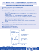
If the motor does not operate:
1. Using the 2″ ratchet strap, securely fasten the top portion of the
Front Arm Stabilizer “CAN” down to a rigid location on the trailer
body or frame.
NOTE:The attachment point on the frame and the ratchet
mechanism must be accessible from ground level while
standing on the Cover Fully Open side of the vehicle.
2. Ratchet the front arm down firmly to the trailer top rail or tarp stops
to prevent movement of front arm from Stored Spring Energy.
3. Using a 10mm socket and wrench, remove the power wires from
the motor terminals.
4. Using a 10mm socket and ratchet wrench, remove the black plastic
motor cap located directly under the motor wire terminals
NOTE:The brake circuit prevents the brake from being completely
removed from the assembly. It is OK to leave the brake motor
hanging from the wire leads.
5. Stand at ground level in front of the tarp axle, and away from the tarp
arms.
6. Slowly release the ratchet strap in small increments.
NOTE:By removing the motor brake, the arm is now free to move
using stored potential spring energy. Letting out the ratchet
strap releases the spring energy and rotate the Arm about the
Front Pivot Pin.
7. Continue to release the ratchet strap in small increments until the cover is Fully
Covered and the Tarp Arm is at its lowest position.
8. If the system does not move with the brake removed, it will be necessary to move
the motor shaft with a 3/4″ hex socket with 12″ extension, and 1/2″ drive ratchet.
Then rotate the motor head clockwise for the passenger side, and counter
clockwise for the driver side until the Tarp Arm is at rest at the Lowest Position.
Tie Motor CAN
to trailer body
to prevent
movement.
Remove
Motor Cap
Hex on
Motor Shaft


1-800-325-9103
PB-SSTR - 17 - www.meyermfg.com
6.0 PRE-OPERATION
WARNING
!
A
lways keep all shields and guards in place and securely fastened.
Keep hands, feet and clothing away.
Verify that the implement is securely fastened to the tractor/truck.
Verify that all electrical/hydraulic connections and bolts/hardware
are tight and securely fastened before operating the implement.
Wear safety glasses to prevent eye injury when any of the
following conditions exist:
ƔWhen fluids are under pressure.
ƔFlying debris or loose material is present.
ƔTools are being used.
DO NOT allow anyone to operate, service, inspect or otherwise
handle this implement until all operators have read and understand
all of the instructional materials in this Owner / Operator’s and
Parts Manual and have been properly trained in its intended usage.
!
CAUTION
6.1 STATIC INSPECTION
Before operating the implement for the first time and each time thereafter, check the following items:
1. Check that all safety signs are in good and legible condition.
2. Check that all lubrication has been completed. Refer to Section 8.1 LUBRICATION.
3. Make sure all guards and shields are in place, secured and functioning as designed.
4. Check the tarp return strap is in good workable condition. Refer to Section 8.2 ADJUSTMENTS.
5. Check the tarp springs for damage.
6. Check for any damage to the tarp or any moving components of the tarp system.
6.2 ELECTRICAL HOOK-UP
Semi-Tractor hookup:
There is an electrical kit that needs to be installed onto the Semi-Tractor.
There is a 2-pin power cable/plug, 4-pin switch cable/plug, a circuit breaker, and a rocker switch that will need
to be installed to operate the tarp system.
To outfit additional Semi-Tractors, call your parts department and order the appropriate kit which may be
different depending on your serial number.
See electrical schematics.
Truck mounts:
There is a 2-pin power cable, 4-pin switch cable, circuit breaker and a rocker switch that will need to be
installed to operate the tarp system.
See Wiring Diagrams on 18 and 19.


Meyer Manufacturing Corporation - 20 - PB-SSTR
6.3 START-UP AND SHUT-DOWN
Disengage electric/ hydraulic power, engage the machine’s parking
brake, stop the engine and make sure all moving components
are completely stopped before connecting, disconnecting,
adjusting or cleaning this equipment.
WARNING
!
A
lways keep all shields and guards in place and securely fastened.
Keep hands, feet and clothing away.
Before operating the implement, look in all directions to ensure
there are no bystanders, especially small children, are in the
work area.
!
CAUTION
This Tarp System is activated using electric power, it’s wired directly to the battery.
6.4 OPERATIONAL CHECKS
WARNING
!
A
lways keep all shields and guards in place and securely fastened.
Keep hands, feet and clothing away.
Run your tarp all the way open and all the way closed to make sure of proper tarp operation.
6.5 CONTROLS
Your Side to Side tarping system comes standard with Roll-Rite’s® patented One-Touch (Automatic) open and
close feature.
• When the switch is held for 2-3 seconds the tarp will automatically open or close.
• Touch the switch while it is in operation, and it will return to manual mode.
• If you hold the switch for longer than 3 seconds, the switch will operate in manual mode.
• This is an amp sensing control and therefore will operate until the amps are met.
NOTE:It is important to follow the wiring diagram as there are different amp requirements between
opening and closing operations. If hooked up backwards, it may cause damage to the system.
• A function light comes with the control, located on the relay at the front of the implement.
• When the motor is running a solid light will emit.
• If there is a malfunction of the unit, it will give a blink code.
• Use the blink code to help resolve the malfunction. See the trouble shooting guide for further details.
• An optional RF control is available. Refer to Section 6.6 OPTIONAL EQUIPMENT
/