Page is loading ...

BRAY/RITE
SINGLE DOOR WAFER TYPE SWING
CHECK VALVES
Installation and Maintenance Manual
BRAY.COM THE HIGH PERFORMANCE COMPANY

BRAY/RITE SINGLE DOOR WAFER TYPE SWING CHECK VALVES
Installation and Maintenance Manual
2 of 76© 2023 BRAY INTERNATIONAL, INC. ALL RIGHTS RESERVED. BRAY.COM The Information
contained herein shall not be copied, transferred, conveyed, or displayed in any manner that would
violate its proprietary nature without the express written permission of Bray International, Inc.
0.0 Definition of Terms 4
1.0 Introduction 6
2.0 Description 7
3.0 Inspection & Unpacking 9
4.0 Storage & Handling 10
5.0 Tools Required 11
6.0 Pre-installation Checklist 11
7.0 Dis-Assembly Instructions for Bray/Rite Single Door
Wafer Swing Check Valves
13
8.0 Re-Assembly Instructions for Bray/Rite Single Door
Wafer Swing Check Valves
14
9.0 Pre-Installation Reminders 15
10.0 Maintenance Requirements and Information 16
11.0 Repairs 17
12.0 Spool Installation for Bray/Rite Single Door Wafer Swing
Check Valves
19
13.0 Body Markings: Nameplate/Serial Number 19
14.0 Safety Warnings 22
15.0 Limitations and Precautions 24
16.0 Non-Shock Pressure-Temperature Ratings 26
17.0 Example Bill of Materials 31
18.0 Typical Bolt/Stud Details 32
19.0 H-100 (External Spring, Weight & Hydraulic Damper),
Special Application Model
34
20.0 SA-01 (External Lever, & Spring), Special Application
Model
37
21.0 SA-1 (External Lever, Spring, & Weight), Special
Application Model
39
22.0 SA-2 (Limit Switch), Special Application Model 42
23.0 SA-3 (Backflush Lever, & External Spring), Special
Application Model
44
TABLE OF CONTENTS

BRAY/RITE SINGLE DOOR WAFER TYPE SWING CHECK VALVES
Installation and Maintenance Manual
3 of 76© 2023 BRAY INTERNATIONAL, INC. ALL RIGHTS RESERVED. BRAY.COM The Information
contained herein shall not be copied, transferred, conveyed, or displayed in any manner that would
violate its proprietary nature without the express written permission of Bray International, Inc.
24.0 SA-4 (External Position Indicator), Special Application
Model
46
25.0 SA-4A (Backflush Lever), Special Application Model 48
26.0 SA-6 (Foot Valve), Special Application Model 50
27.0 SA-7 (Emergency Shut-O, Fusible Link), Special
Application Model
51
28.0 SA-10 (Dual Balanced Weights), Special Application
Model
54
29.0 SA-16 (External Weight & Lever), Special Application
Model
57
30.0 SA-40 (External Compression Spring), Special
Application Model
60
31.0 SA-40A (External Compression Spring, Weight & Lever),
Special Application Model
63
32.0 SA-50 (External Compression Spring, Weight &
Hydraulic Damper), Special Application Model
66
33.0 PVC (Plastic Body), Special Application Model 70
34.0 PVC (Plastic Body) SA-4A (Backflush Lever), Special
Application Model
73

BRAY/RITE SINGLE DOOR WAFER TYPE SWING CHECK VALVES
Installation and Maintenance Manual
4 of 76© 2023 BRAY INTERNATIONAL, INC. ALL RIGHTS RESERVED. BRAY.COM The Information
contained herein shall not be copied, transferred, conveyed, or displayed in any manner that would
violate its proprietary nature without the express written permission of Bray International, Inc.
0.0 DEFINITION OF TERMS:
All information within this manual is relevant to the safe operation
and proper care of your Bray valve. Please understand the
following examples of information used throughout this manual.
0.0 IDENTIFIES CHAPTER HEADING
0.00 Identifies and explains sequential procedure to be performed.
NOTE: Provides important information related to a procedure.
SAFETY STATEMENTS: To prevent unwanted consequences.
CAUTION
Indicates a potentially hazardous situation which, if not avoided,
may result in minor or moderate injury.
NOTICE
Used without the safety alert symbol, indicates a potential
situation which, if not avoided, may result in an undesirable
result or state, including property damage.
WARNING
Indicates a potentially hazardous situation which, if not avoided,
could result in death or serious injury.
READ AND FOLLOW THESE INSTRUCTIONS CAREFULLY.
SAVE THIS MANUAL FOR FUTURE USE.

BRAY/RITE SINGLE DOOR WAFER TYPE SWING CHECK VALVES
Installation and Maintenance Manual
5 of 76© 2023 BRAY INTERNATIONAL, INC. ALL RIGHTS RESERVED. BRAY.COM The Information
contained herein shall not be copied, transferred, conveyed, or displayed in any manner that would
violate its proprietary nature without the express written permission of Bray International, Inc.
NOTE: This is a generic instruction manual common to above
listed Bray/Rite standard check valves.
Please refer to the certified assembly drawing supplied with your
order, for any dimensional and/or operational parameters that
may not appear in this publication.

BRAY/RITE SINGLE DOOR WAFER TYPE SWING CHECK VALVES
Installation and Maintenance Manual
6 of 76© 2023 BRAY INTERNATIONAL, INC. ALL RIGHTS RESERVED. BRAY.COM The Information
contained herein shall not be copied, transferred, conveyed, or displayed in any manner that would
violate its proprietary nature without the express written permission of Bray International, Inc.
1.0 INTRODUCTION:
1.1 Instructions provided herewith should be thoroughly read and
understood prior to actioning any installation or maintenance
activities. Bray recommends that only experienced and skilled
personnel be allowed to install and maintain these products.
This manual is an overview only and does not in anyway replace
the vital functions of on-site, process engineer(s), pipe fitter(s),
etc. Please retain this manual in an easily accessible location for
any and all employees that may need to reference it routinely.
1.2 Valve Selection Confirmation:
A properly functioning valve requires adequate selection review
process. Before installation eorts should be made to ensure
valve being oered fits with application requirements, by
evaluating some common characteristics (non-exhaustive list):
> Applicable operating conditions (condensation, flow reversal,
frequency of operation, pressure drop, throttling, vacuum,
etc.).
> Design and working pressure/temperature requirements.
> Materials of construction.
> Pipeline media flow-rate and viscosity.
> Service media type (abrasive, corrosive, dirty, gas, liquid, etc.)
> Site location for installation, ensuring adequate distance from
sources of turbulence.
1.3 Modern piping applications demand better features, performance
and economy in a check valve.
1.4 Bray/Rite Features:
> Compactness
> Minimum weight
> Simplicity
1.5 Bray/Rite Performance Characteristics:
> Bubble-tight shut-o
> Low pressure drop
> Non-slamming
> Rapid response
> Silent operation
1.6 Bray/Rite’s combination of these features and performance
characteristics ensure long service life of Bray/Rite products.

BRAY/RITE SINGLE DOOR WAFER TYPE SWING CHECK VALVES
Installation and Maintenance Manual
7 of 76© 2023 BRAY INTERNATIONAL, INC. ALL RIGHTS RESERVED. BRAY.COM The Information
contained herein shall not be copied, transferred, conveyed, or displayed in any manner that would
violate its proprietary nature without the express written permission of Bray International, Inc.
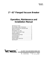
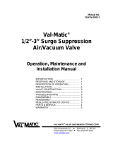
2.0 DESCRIPTION:
2.1 Bray/Rite Single Door Wafer Swing Check Valves consist of a
compact Body (1) with a single plate Disc (12) attached to a Hinge
(2) which in turn is supported by a Hinge Pin (7) inside an o-
center body cavity.
2.2 The Disc is mechanically biased to the closed position by a
torsional Spring (5) located between the two Hinge (2) lugs.
The Hinge Pin (7) is retained by two NPT Pipe Plugs (8) inside the
Body (1). The Seat (3) can be:
> Metal to Metal
> Metal to Resilient (Buna, EPDM, Teflon, Viton, etc.)
2.3 An Eyebolt (10) is typically shipped separately in the check
valve box from Bray/Rite to avoid damage resulting from
transportation to it or the accompanying valve/packaging.
Item (10) can be installed/threaded on the top of the Bray/Rite
single door wafer swing check valves prior to assembly & has
the purpose of aiding alignment/installation. Once successfully
installed in proper alignment, the Eyebolt (10) can be removed
after installation if required.
2.4 The Nameplate (11) located on the top pad of the body specifies:
> Manufacturer Name (Bray/Rite)
> Pressure @ Temperature Rating, Design Code, Serial Number,
and Part Number
> Body Material, Size, Class, and Trim
2.5 Bray/Rite Single Door Wafer Swing Check Valves are typically
designed to open when a pressure of less than 1 psi (.07 bar) is
applied across the face of the Disc (12). Bray/Rite Single Door
Wafer Swing Check Valves are provided for installation inside the
bolt circle and between standard flanges, using a suitable gasket
for the application, or as specified.
Standard
Name plate illustrated
Additional tag
B16.34
Not required.
UL/FM
Not required.
Standard
Name plate illustrated
Additional tag:
Standard
Name plate illustrated
Additional tag
B16.34
Not required.
UL/FM
Not required.
Standard
Name plate illustrated
Additional tag:
10
9
13
1
11
7
14
2
5
6
6
15
12
3
8
8

BRAY/RITE SINGLE DOOR WAFER TYPE SWING CHECK VALVES
Installation and Maintenance Manual
8 of 76© 2023 BRAY INTERNATIONAL, INC. ALL RIGHTS RESERVED. BRAY.COM The Information
contained herein shall not be copied, transferred, conveyed, or displayed in any manner that would
violate its proprietary nature without the express written permission of Bray International, Inc.
2.8 All Bray/Rite Single Door Wafer Swing Check Valves are
hydrostatically tested in accordance with MSS-SP-61, ANSI B16.34
and API-598 test procedures.
NUMBER
PART
Information in this drawing is provided for reference only.
http://www.mcmaster.com
3014T58
Steel Eyebolt with
Shoulder - for Lifting
© 2021 McMaster-Carr Supply Company
2.6 Bray/Rite’s combination of these features and performance
characteristics ensure long service life of Bray/Rite products.
2.7 Bray/Rite Single Door Wafer Swing Check Valves are normally
installed with the Eyebolt pointing vertically upwards in a
horizontal run of pipe, with the arrow on the Body pointing in the
direction of flow.

BRAY/RITE SINGLE DOOR WAFER TYPE SWING CHECK VALVES
Installation and Maintenance Manual
9 of 76© 2023 BRAY INTERNATIONAL, INC. ALL RIGHTS RESERVED. BRAY.COM The Information
contained herein shall not be copied, transferred, conveyed, or displayed in any manner that would
violate its proprietary nature without the express written permission of Bray International, Inc.
3.0 INSPECTION & UNPACKING:
3.1 INSPECTION OF PACKAGING:
Care should be given to inspect the product packaging for
damage on all goods received while the freight carrier is still
present. Any observed packaging damage should be reported
immediately to the carrier, & any claim requirements followed
through.
3.2 UNPACKING: Open the shipping container with adequate care
ensuring to leave containers intact.
3.3 Any/all externally listed container specific markings must be
followed.
3.4 Remove any packing material and carefully lift the product(s)
from the container.
3.5 All shipping container and packing materials provided should be
used (when space permits to do so) for product storage.
3.6 INSPECTION OF GOODS:
Care must be given to do a thorough visual inspection
of all goods received in a timely manner. Any damage, or
missing components expected where the expectation relates
to mishandling during transit, should be noted to carrier
immediately.
3.7 Items that are damaged during shipment fall under the liability
involved with quoted incoterms. If damage is observed, file a
claim with the freight carrier immediately. Refer to Bray Terms
and Conditions for Sale for our full warranty policy.
3.8 Preparation for Shipment:
Bray/Rite valves are normally shipped from the factory in
a combination of boxes, crates, or on skids (size & model
dependent).
3.9 Product packaging (when customer intends to ship to an
additional location) must be completed in a manner to protect
against deterioration and physical damage during transit and
storage.
3.10 Any protruding accessories, deemed to be at heightened risk
to damage by their design (such as the levers, springs, and/
or weights) may (if required for safekeeping) be removed &
packaged separately.
3.11 All customer-driven packing requirements, must be clearly called
out and quoted separately prior to placing the purchase order.
3.12 Any/all special shipping conditions must be reviewed by Bray/
Rite for compliance at time of quotation, & be clearly defined in
writing. Such instructions also need to be of a quality standard
such that they adequately protect (a.) goods during transport, &
(b.) goods during site storage requirements.

BRAY/RITE SINGLE DOOR WAFER TYPE SWING CHECK VALVES
Installation and Maintenance Manual
10 of 76© 2023 BRAY INTERNATIONAL, INC. ALL RIGHTS RESERVED. BRAY.COM The Information
contained herein shall not be copied, transferred, conveyed, or displayed in any manner that would
violate its proprietary nature without the express written permission of Bray International, Inc.
4.0 STORAGE & HANDLING:
Storage:
4.1 SHORT TERM: For short term storage (defined as within 3 months
of order release) all products must be kept indoors in in the
original packaging in a moderate temperature range (defined as
between 32°F and 85°F). General guidelines for short and long
term storage:
> Do not stack the valves on top of each other.
> Do not leave valves outdoor or exposed to the elements/
sunlight.
> Keep any/all protective end-caps on to protect the valve
against damage from dust, dirt, etc.
4.2 LONG TERM: For long term storage (defined as greater than 3
months after order release), all valves must be kept in a clean,
dry, fire-resistant, flood resistant, temperature controlled, and
adequately ventilated, storage facility.
4.3 All valves should be adequately secured in place by banding/
other means to prevent damage resulting from valve movement.
4.4 A desiccant may be necessary (based upon the local,
environmental storage conditions) for long-term storage
situations.
4.5 OUTDOOR:
Where outdoor storage is a necessity, special crating and valve
packaging can be provided, at an additional charge but must be
quoted before the order has been placed. Periodic checks on
valves in storage are required to ensure all conditions listed above
have been met.
4.6 HANDLING:
Most standard check valves are supplied with a removable lifting
Eyebolt (10) which must be used to lift the valve, & support the
valve during alignment/installation. Improper use will result in
valve body damage.
4.7 NOTICE
Valve should never be used as pipeline alignment tool. The area
where the valve will be installed should have proper spacing
aorded by pipeline flanges being mounted on both sides of the
space prior to valve install.
NEVER lift or move the valve assembly by means of any
attached accessory, internal part, or mounting holes.
4.8 Any provided valve protection accessories such as wooden plates
or plastic caps should not be removed until the valves are ready
to be installed, so as to keep foreign contaminants out.
4.9 Transportation for all packed goods should be carried out in
accordance with relevant site & territory safety regulations.

BRAY/RITE SINGLE DOOR WAFER TYPE SWING CHECK VALVES
Installation and Maintenance Manual
11 of 76© 2023 BRAY INTERNATIONAL, INC. ALL RIGHTS RESERVED. BRAY.COM The Information
contained herein shall not be copied, transferred, conveyed, or displayed in any manner that would
violate its proprietary nature without the express written permission of Bray International, Inc.
5.0 TOOLS REQUIRED:
Hammer, hex key, nose punch, thread sealant, and wrench.
5.1 NOTICE
Personal protective equipment such as eye/foot/hand
protection is required when installing or maintaining wafer
check valves.
5.2 CAUTION
Please use caution. Preset spring(s) have capacity to cause
serious injury when tension is released.
6.0 PRE-INSTALLATION CHECKLIST:
6.1 NOTICE
Location for valve should be selected based on distance from
turbulent conditions.
> Media flowing to valve should be filtered first to remove
unwanted debris.
> Non-compliance can eect check valve sealing, and adversely
eect optimal performance.
> Valve pressure/temperature limits must align with the
application requirements.
> Valve materials must be compatible with line media it will
experience.
Before installation, all valves must be checked for any/all foreign
materials that may have become entrapped during storage/
transportation. All contaminants should be removed by with
solvent dampened cloths.
Sealing surfaces should be inspected to ensure there is no
damage (cuts or nicks) & that general appearance is clean and
smooth.
Check Valves must be placed a distance 5 to 10 pipe diameters
away from any/all source of turbulence such as elbows,
expansions, pumps, reductions, swages, tees, etc).
6.2 CAUTION
Standard check valves are typically designed for steady flow
conditions, and not for use in physical/thermal shock-load
applications (via reciprocating pump, compressor). In this type
of application, standard check valve will not perform eciently
and have a greater tendency to fail.
(continued)

BRAY/RITE SINGLE DOOR WAFER TYPE SWING CHECK VALVES
Installation and Maintenance Manual
12 of 76© 2023 BRAY INTERNATIONAL, INC. ALL RIGHTS RESERVED. BRAY.COM The Information
contained herein shall not be copied, transferred, conveyed, or displayed in any manner that would
violate its proprietary nature without the express written permission of Bray International, Inc.
6.3 Standard check valves are designed to operate eciently in flow
rate scenarios between 5 ft./sec. to 10 ft./sec. Operating outside
of this range will adversely eect performance & may lead to
premature failure.
6.4 Any provided valve protection accessories such as wooden plates
or plastic caps should not be removed until the valves are ready
to be installed, so as to keep foreign contaminants out.
6.5 Step 1:
Remove the plastic flange protectors (if present) and other
packaging materials from the Check Valve
6.6 CAUTION
For vertical down-flow applications, consult Bray/Rite Technical
team for custom solutions that may be available.
6.7 Step 2:
Orient the valve such that the flow arrow (cast/etched onto
body or printed on the nameplate) points in the direction of the
desired pipeline flow.
6.8 Step 3:
The appropriate material handling equipment must be used in
order to prevent injury and possible damage to the check valve
and personnel responsible for installation.
6.9 CAUTION
OPERATION START-UP:
After the installation has been verified (at start-up, & after
shut-down conditions) as safe and complete, it is important
for operators to start the pipe system flow gradually. The goal
is to not stress the check valve (and other line equipment) via
sudden shock.

BRAY/RITE SINGLE DOOR WAFER TYPE SWING CHECK VALVES
Installation and Maintenance Manual
13 of 76© 2023 BRAY INTERNATIONAL, INC. ALL RIGHTS RESERVED. BRAY.COM The Information
contained herein shall not be copied, transferred, conveyed, or displayed in any manner that would
violate its proprietary nature without the express written permission of Bray International, Inc.
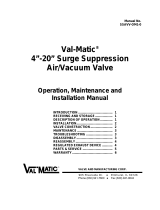
7.0 DIS-ASSEMBLY INSTRUCTIONS FOR BRAY/RITE SINGLE
DOOR WAFER SWING CHECK VALVES:
TOOLS REQUIRED: Hammer, hex key, nose punch, thread sealant,
and wrench.
7.1 The simple design of the Bray/Rite Single Door Wafer Swing
Check Valves valve permits for easy assembly and disassembly.
The following assembly procedure applies to all Bray/Rite Single
Door Wafer Swing Check Valves.
7.2 To Dis-assemble the valve:
7.3 a.) Place the Body (1) in a horizontal position with the Disc (12)
assembly showing.
b.) Remove the Plugs (8) on both side of the Body (1) by using a
hex-key or wrench.
c.) Hold the Spring (5) in position and slide the Pin (7) out of
the Body (1). Use of Hammer and Nose Punch may be required
to gently tap Pin (7) from one side out the opposite side. Pay
attention to original orientation of Spacers (6).
d.) Slowly release the pressure on the Spring (5) and remove it
from the valve.
e.) The Hinge-Disc Assembly (2, 12, 15) can now be lifted from
the Body (1).
f.) Remove the O-Ring (14) if required.
7.4 We recommend Bray/Rite O-Rings get sourced everytime the
valve is being repaired.
Item Description
1 Body
2 Hinge
3 Seat
5 Spring
6 Spacer
7 Pin
8 Plug
Item Description
9 Lock Nut
10 Eye Bolt
11 Name Plate
12 Disc
13 Rivet
14 O-Ring
15 Disc-Nut
10
9
13
1
11
7
14
2
5
6
6
15
12
3
8
8

BRAY/RITE SINGLE DOOR WAFER TYPE SWING CHECK VALVES
Installation and Maintenance Manual
14 of 76© 2023 BRAY INTERNATIONAL, INC. ALL RIGHTS RESERVED. BRAY.COM The Information
contained herein shall not be copied, transferred, conveyed, or displayed in any manner that would
violate its proprietary nature without the express written permission of Bray International, Inc.
8.0 RE-ASSEMBLY INSTRUCTIONS FOR BRAY/RITE SINGLE
DOOR WAFER SWING CHECK VALVES:
To re-assemble the valve:
8.1 a.) Clean all parts with acceptable solvent while valve is being
serviced.
b.) Place the Body (1) in a horizontal position with the seating face
pointing upwards.
c.) If required, insert O-Ring (14) in the seat groove. (See below
for installation instructions).
d.) Place the Hinge-Disc Assembly (2, 12, 15) in the body cavity.
e.) Slide Spacer in between Body (1) and adjacent Hinge (2) lug
while inserting the Pin (7) through the Plug (8) hole on either side
of the Body (1) and slide the first Spacer (6) in between the
Body (1) and adjacent Hinge (2) lug.
f.) Press Spring (5) between the Hinge (2) lugs and Body (1)
cavity, then advance the Pin (7) through the Spring (5) and the
second Hinge (2) lug.
g.) Slide the second Spacer (6) between the Body and hinge lug
and advance the Pin (7) into the Body (1). Position the Hinge
Pin (7) central to the valve Body (1) prior to the installation of the
retaining Plugs (8).
h.) Check that the Spring (5) ends are seated properly.
i.) Apply Teflon tape or sealing compound if required by
application on retaining Plugs (8), install Plugs and tighten both
sides with an hex key or wrench.
8.2 Verification:
a) check that the valve opens and closes freely.
b) check the Pin-Disc (7, 12) connection to ensure it has adequate
freedom of movement provided for the Disc (12) to adapt a self-
aligning position with the Seat (3).
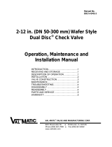
8.3 NOTICE
INSERT O-RING AS FOLLOWS
(a.) Place O-Ring (14) on top of seat groove.
(b.) To prevent looping, insert the O-Ring as shown by pressing
the O-Ring into the groove in the following numerical sequence.
8.4 It is important to smooth out the O-Ring (14) so that there are no
visible ripples or loops.
8.5 It should be noted that the O-Ring groove is slightly larger than
the O-Ring (14) and it follows that the O-Ring (14) must be hoop
stretched to engage the groove.
Right Wrong

BRAY/RITE SINGLE DOOR WAFER TYPE SWING CHECK VALVES
Installation and Maintenance Manual
15 of 76© 2023 BRAY INTERNATIONAL, INC. ALL RIGHTS RESERVED. BRAY.COM The Information
contained herein shall not be copied, transferred, conveyed, or displayed in any manner that would
violate its proprietary nature without the express written permission of Bray International, Inc.
9.0 PRE-INSTALLATION REMINDERS:
9.1 Install all flangeless wafer valves between two pipe flanges (with
gaskets on the contact faces) of the same series as the valve,
centred in line by the surrounding flange bolts, and tightened as
per industry standard practice.
9.2 All internal parts designed to move should operate freely.
9.3 The normal installation of a Bray/Rite Single Door Wafer Swing
Check Valves valve is for horizontal flow with the hinge Pin (7) in
the horizontal upper position, or for vertical flow, with the flow
direction upwards.
9.4 Bolting Guidance:
1 3
4 2
Four-Bolt
3 4
5 2
1 1
2
3
5
6
4
Five-Bolt Six-Bolt
1
67
2
58
310
11
12
49
End Start 1
72
9
1110
54
12
8
36
End
Start
WAFER VALVE WITH THROUGH-STUDS
RECOMMENDED 2 THREADS BEYOND NUT
(PER SIDE)
RECOMMENDED 2 THREADS BEYOND NUT
(PER SIDE)
WASHERWASHER
NUTNUT
WAFER
BODY
FLANGE FLANGE
RAISED FACE (WHEN APPLICABLE)RAISED FACE (WHEN APPLICABLE)
GASKETGASKET
SEAT RETAINER
9.5 When removing a Bray/Rite Single Door Wafer Swing Check valve
from the line, only the top half of the studs need to be removed
and the others loosened.
(continued)

BRAY/RITE SINGLE DOOR WAFER TYPE SWING CHECK VALVES
Installation and Maintenance Manual
16 of 76© 2023 BRAY INTERNATIONAL, INC. ALL RIGHTS RESERVED. BRAY.COM The Information
contained herein shall not be copied, transferred, conveyed, or displayed in any manner that would
violate its proprietary nature without the express written permission of Bray International, Inc.
10.0 MAINTENANCE REQUIREMENTS AND INFORMATION:
VALVE REMOVAL FOR INSPECTION
10.1 WARNING
Before removing any check valve from the pipeline, ensure the
media flowing in the pipeline is confirmed and any/all special
handling protocols are followed/understood. Always review the
applicable Material Safety Data Sheet (MSDS) for the media in
advance of work performed.
Before removing any check valve from the pipeline, the vessel
pressure must be reduced to atmospheric by means of suction/
venting/other. Failure to do so may result in serious bodily
injury.
10.2 Shutting o the upstream pump acts to isolate the check valve.
10.3 Close the downstream isolation valve.
10.4 Drain the system section featuring the check valve as much as
possible.
IMPORTANT:
9.6 CAUTION
1.) Double check the flow direction arrow on the body before
inserting the Bray/Rite Single Door Wafer Swing Check valve
between the flanges.
2) Pipeline flanges must be parallel and have the same pressure
class rating as the valve.
3.) There must be no obstructions in the mating flange(s), or
pipe bore(s) as this would prevent the valve from opening fully,
leading to premature valve failure.
10.5 Vent the line on both sides of the check valve to relieve pressure
from the check valve. Always loosen the outlet side first.
10.6 Once pressure has been relieved successfully, move to loosen the
inlet side.
10.7 Remove check valve from the pipeline, inspecting internals for
signs of damage, & degradation.
10.8 If replacement parts are required, use exact valve drawing
procured to identify any/all parts required for repair. Alternately
please contact Bray/Rite for repair recommendations.

BRAY/RITE SINGLE DOOR WAFER TYPE SWING CHECK VALVES
Installation and Maintenance Manual
17 of 76© 2023 BRAY INTERNATIONAL, INC. ALL RIGHTS RESERVED. BRAY.COM The Information
contained herein shall not be copied, transferred, conveyed, or displayed in any manner that would
violate its proprietary nature without the express written permission of Bray International, Inc.
11.0 REPAIRS:
LEAKAGE CONDITIONS:
11.1 A schedule for routine inspection should be implemented and
performed.
11.2 NOTICE
If leakage is identified, during maintenance check the flange
gasket, and flange bolt torque to ensure they are within
acceptable limits. Valve removal for inspection may be required.
See above notes.
11.3 MINIMAL FLOW:
While flow is halted, verify flow direction arrow is installed in
correct alignment with required direction of flow.
11.4 SLAM CONDITIONS:
Initiate valve removal to inspect spring condition and tension.
Consult Bray/Rite technical sta to ensure valve is sized
appropiately.
11.5 VIBRATION CONDITIONS:
When valves are found to be vibrating excessively, firstly Verify
that flow rate is within acceptable ranges (5 ft./sec. to 10 ft./sec.).
11.6 Verify site installation location has at least 5 to 10 pipe diameters
length from any source of turbulence (ie. elbows, expansions,
pumps, reductions, swages, tees, etc.).
11.7 For replacement of O-Rings (14) refer to Section 7.0 and 8.0 for
Assembly and disassembly instructions of Bray/Rite Single Door
Wafer Swing Check Valves.
11.8 When visible damage is observed on O-Rings (14), they should be
replaced with Bray/Rite sourced replacement O-Rings (14).
11.9 The standard O-Ring (14) numbers, Plug sizes and Hex key sizes
for class 125/150/300 are listed below for valves 2”-42”. For other
classes, contact the factory.
(continued)

BRAY/RITE SINGLE DOOR WAFER TYPE SWING CHECK VALVES
Installation and Maintenance Manual
18 of 76© 2023 BRAY INTERNATIONAL, INC. ALL RIGHTS RESERVED. BRAY.COM The Information
contained herein shall not be copied, transferred, conveyed, or displayed in any manner that would
violate its proprietary nature without the express written permission of Bray International, Inc.
Valve Size O-Ring Size
Models 210 O-Ring Size
Models 212 Plug Size
NPT Hex Key
Size
2” 128 128 1/4” 1/4”
2.5” 133 133 1/4” 1/4”
3” 141 141 3/8” 5/16”
4” 235 235 3/8” 5/16”
5” 242 242 3/8” 5/16”
6” 248 248 3/8” 5/16”
8” 259 259 1/2” 3/8”
10” 368 368 1/2” 3/8”
12” 447 447 3/4” 9/16”
14” 449 -3/4” 9/16”
16” 453 -3/4” 9/16”
18” 455 - 3/4” 9/16”
20” 458 - 1” 5/8”
24” 462 - 1” 5/8”
30” 471 - 1 1/2”* 1 1/4”*
36” 473 - 1 1/2”* 1 1/4”*
42” 3/8 x 110” - 2”* 1 5/16”*
Applies to all models (strictly size dependent). * Square Head Plug
11.10 O-Ring, Plug, & Hex Key Sizes:

BRAY/RITE SINGLE DOOR WAFER TYPE SWING CHECK VALVES
Installation and Maintenance Manual
19 of 76© 2023 BRAY INTERNATIONAL, INC. ALL RIGHTS RESERVED. BRAY.COM The Information
contained herein shall not be copied, transferred, conveyed, or displayed in any manner that would
violate its proprietary nature without the express written permission of Bray International, Inc.
12.0 SPOOL INSTALLATION FOR BRAY/RITE SINGLE DOOR
WAFER SWING CHECK VALVES:
12.1 When a standard flanged valve is replaced with a shorter face-
to-face wafer valve model, a spool piece can be inserted with
the Bray/Rite Single Door Wafer Swing Check valve to obtain the
required face to face dimension. The installation instructions in
Section 8.0 above apply.
13.0 BODY MARKINGS, NAMEPLATE/SERIAL NUMBER:
13.1 Nameplates: The serial number gives the ability to trace valve
internals and the date of manufacture of the valve.
13.2 UL/FM valves are identified by their nameplate.

BRAY/RITE SINGLE DOOR WAFER TYPE SWING CHECK VALVES
Installation and Maintenance Manual
20 of 76© 2023 BRAY INTERNATIONAL, INC. ALL RIGHTS RESERVED. BRAY.COM The Information
contained herein shall not be copied, transferred, conveyed, or displayed in any manner that would
violate its proprietary nature without the express written permission of Bray International, Inc.
BRAY/RITE SINGLE DOOR WAFER SWING CHECK VALVE PART NUMBER (SERIES SDCV):
EXAMPLE PART NUMBER: V0212CBT
SIZE PRESSURE CLASS BODY MATERIAL INSERT (CI/CS/DI)/INTEGRAL (SS/HIGHER) SPACER MATERIAL MODEL CODE SPECIAL APPLICATION
ACCESSORIES
INCHES CODE CLASS CODE MATERIAL CODE MATERIAL CODE
MATERIAL CODE
MATERIAL CODE SERIES (COLOUR) CODE CODE ACCESSORY
1
***Only mfr in 316SS
or higher grade
V01 ASME 125 12 254SMO Material
X, then
254SMO at end
of part number
A479-316 as
standard supply ZAPI 594 #600/PN64
***our wider face to face 201 BACKFLUSH LEVER SA-4A
1.5
***Only mfr in CS or
higher grade
V015 ASME 150 15 Alloy20
X, then A20 at
end of part
number
PTFE T 203 BACKFLUSH LEVER & EXTERNAL
SPRING SA-3
2 V02 larger become model
205 automatically.
30 ASTM A 126 CLB ***only manufacture
in ANSI 125 or PN10/16 ***integral seat C- OTHER ** API 594 #2500 our wider
face to face 204 DUAL BALANCED WEIGHTS SA-10
2.5 V025 ASTM A 216 WCB ***o-ring mounted in
a 304 stainless steel seat ring SAPI 594 (ANSI125, 150,
300, PN10, PN16, PN25) 205 EMERGENCY SHUT-OFF, FUSIBLE LINK SA-7
3 V03
ASTM A 395 ***only manufacture in
ANSI 150 or PN10/16 ***o-ring mounted
in a 304 stainless steel seat ring
D
EXTERNAL COMPRESSION SPRING
APPROVE SMALLER SIZES
SA-40
4 V04 ASTM A351 CF8M **integral seat X
EXTERNAL COMPRESSION SPRING &
WEIGHT & HYDRAULIC DAMPER (SA-40
LARGER)
SA-50
5 V05
EXTERNAL COMPRESSION SPRING,
ENGINEERING TO APPROVE SMALLER
SIZES
SA-40A
6 V06 EXTERNAL LEVER SPRING & WEIGHT SA-1
8 V08 EXTERNAL POSITION INDICATOR SA-4
10 V10 SA-01
12 V12
EXTERNAL SPRING & WEIGHT, &
HYDRAULIC DAMPER (SA-01 SPRING) H-100
14
***Only o ered in CS
or SS Bodies, SS
spacer
V14 EXTERNAL WEIGHT & LEVER SA-16
16
***Only o ered in CS
or SS Bodies, SS
spacer
V16
18
***Only o ered in CS
or SS Bodies, SS
spacer
V18
20
***Only o ered in CS
or SS Bodies, SS
spacer
V20
24
***Only o ered in CS
or SS Bodies, SS
spacer
V24
30
***Only o ered in CS
or SS Bodies, SS
spacer
V30
36
***Only o ered in CS
or SS Bodies, SS
spacer
V36
42
***Only o ered in CS
or SS Bodies, SS
spacer
V42
48
***Only o ered in CS
or SS Bodies, SS
spacer
V48
54
***Only o ered in CS
or SS Bodies, SS
spacer
V54
1
***our wider face to face
API 594 #900/1500
ASME 600 60
ASME 900 90
ASME 1500 150
ASME 2500 250
PN 10 10
PN 16 16
PN 25 25
PN 40 40
PN 64 64
Heavy Duty Hinge ASME/
DIN 260
STANDARD ASME/DIN
***(ANSI 125, 150, 300,
PN10, PN16, PN25)
LEAVE BLANK (STANDARD
210 SERIES)
PVC Models PEZ
CUSTOMER-SPECIFIC
SERIES CODE
ANSI 125, cast iron body,
Te on integral seat, te on
spacer.
12C37
ANSI 150, carbon steel
body, Te on integral seat,
Te on spacer.
15S37
ANSI 300, carbon steel
body, Te on integral seat,
Te on spacer, welded plugs.
30S17
ANSI 300, carbon steel
body, Te on integral seat,
Te on spacer, welded
plugs.
30S27
ANSI 300, carbon steel
body, Te on integral seat,
Te on spacer, welded
plugs.
30S47
Carbon steel body, Te on
integral seat, standard
spring with a welded
seat.
S27
Carbon steel body,
EPDM integral seat. S34
FLANGED BODY SA-11
Carbon steel body, Viton
integral seat. S35
Carbon steel body, buna
integral seat. S36
Carbon steel body, Te on
integral seat, standard
spring or heavy duty spring
depending on the size.
S37
Carbon steel body, Te on
integral seat, light duty
spring.
S47
TEFLON T
TEFLON ENCAPSULATED
SILICONE TES
Duplex 6A
X, then 6A at
end of part
number
Duplex 5A X, then 5A at end
of part number
Hastelloy C-22
X, then C22 at
end of part
number
Hastelloy C-276
X, then C276 at
end of part
number
Monel M-53-1 Valves**Body/Disc/Seat/
Trim
X, then MMM at
end of part
number
SS 316L
X, then 6L at
end of part
number
TITANIUM X, then T at end
of part number
OTHER ** -
60
***Only o ered in CS
or SS Bodies, SS
spacer
V60
VITON V
FOOT VALVE SA-6
LIMIT SWITCH SA-2
EPDM E
METAL M
BUNA-N (DEFAULT) B
INSERT/RESILIENT
Miscellaneous Notes: ***Pressure Boundary Components = Body, Plugs. We typically sell repair kits (everything except the body) as spare parts for of our check valves.
EXAMPLE PART NUMBERS BY MATERIAL
EXAMPLE PART NUMBERS (210) EXAMPLE PART NUMBERS (205)
V0212CBT V0212CBT205
V0215DBT V0215DBT205
V0215SBT V0215SBT205
V0215XBT V0215XBT205
V0230SBZ V0230SBZ205
V0230XBZ V0230XBZ205
** = Available in most exotic materials, please consult factory. / *** = Inserted pressed-in interference seat at a minimum of 304 SS for carbon steel and ductile iron bodies, or seat is integral to body.
Note 1: Spacers are located on both sides of the disc hinge, ensuring a uniform seal. / Note 2: The standard Check Rite is a wafer body style. Flanged Ends, RTJ style and other connections are available, please consult factory.
2
BRAY/RITE SINGLE DOOR WAFER SWING CHECK VALVE PART
NUMBER (SERIES SDCV) + ULC/FM:
EXAMPLE PART NUMBER: V02 212
SIZE MODEL CODE
INCHES CODE SERIES (COLOUR) CODE
1V01
ULC FM APPROVED ASME*
***ANSI 125 cast iron body,
stainless steel disc & trim, buna
integral seat, Teon spacers.
212
1.5 V015
ULC FM APPROVED DIN*
***PN10/16 cast iron body,
stainless steel disc & trim, buna
integral sear, Teon spacers.
312
2V02
2.5 V025
3V03
4V04
5V05
6V06
8V08
10 V10
12 V12
14 V14
16 V16
18 V18
20 V20
24 V24
30 V30
36 V36
42 V42
48 V48
54 V54
60 V60
EXAMPLE PART NUMBERS BY MATERIAL
EXAMPLE PART NUMBERS: EXAMPLE PART NUMBERS:
V02212
V02312
V025212
V025312
V03212 V03312
V0421 V04312
V0521 V05312
V06212 V06312
V08212 V08312
V10212 V10312
V12212 V12312
* = ULC Approved under NFPA No. 11, 13, 14, 15, 20, 22, 24. FM Approved.
** = Available in most exotic materials, please consult factory.
Note 1: Spacers are located on both sides of the disc hinge, ensuring a uniform seal.
1
/