
Serial number:
Date of purchase:
/ /
/ /
Don’t forget to register your machine at:
www.euroboor.com/register
[ only when registered you benefit from extended warranty ]
User manual
V 1.0 EN | December 2020
Magnetic drilling machine
ECO.100/4
with 2-way electromagnet and fixed base
ECO.100/4 D
with 2-way electromagnet and swivel base

2
Congratulations on purchasing this premium magnetic drilling machine. At EUROBOOR we strive to
exceed our customers’ expectations by developing and providing premium and innovative portable
drilling and cutting solutions. We believe that a professional like you must be able to rely on a
professional supplier. Which has led us to become a major player in the industrial world, with our
own factory and several offices worldwide. All because we have always listened to our customers
and to the demands from the market.
Our vision is focused on developing innovative portable tools that add value for our customers and
facilitate them in their daily work. We never lose sight of sustainability, time savings and cost savings.
Enjoy your new machine!
Before operating your new magnetic drilling machine, please first read all instructions. You find the
instructions in this manual and on the warning label on your machine. With proper use, care and
maintenance your machine will provide you with years of premium drilling performance.
TO REDUCE THE RISK OF INJURY USER MUST READ AND UNDERSTAND ALL INSTRUCTIONS
To view all our offices and their contact information please visit: www.euroboor.com

3
Table of contents
ECO.100/4 .................................................................................................................................... 1
ECO.100/4 D ................................................................................................................................. 1
Table of contents ......................................................................................................................... 3
1. Safety ....................................................................................................................................... 4
1.1 General safety instructions ........................................................................................................... 4
1.2 Specific safety information ............................................................................................................ 6
2. Description ............................................................................................................................... 8
2.1 Intended use .................................................................................................................................. 8
2.2 Description and features ............................................................................................................... 8
2.3 Case content .................................................................................................................................. 9
2.4 Serial number ................................................................................................................................ 9
2.5 Technical data.............................................................................................................................. 10
2.6 Symbols ....................................................................................................................................... 11
2.7 Environmental ............................................................................................................................. 12
3. Preparation & adjustment ...................................................................................................... 13
3.1 Assembly ..................................................................................................................................... 13
3.2 Prior to use .................................................................................................................................. 14
4. Using the machine .................................................................................................................. 16
4.1 Control panel ............................................................................................................................... 16
4.2 Electromagnet ............................................................................................................................. 16
4.3 Morse taper arbor ....................................................................................................................... 19
4.4 Manual gearbox ........................................................................................................................... 20
4.5 Switching motor on and off ......................................................................................................... 20
4.6 Motor rotation ............................................................................................................................ 20
4.7 Motor speed control ................................................................................................................... 21
4.8 Torque control ............................................................................................................................. 21
4.9 Overheat protection .................................................................................................................... 21
4.10 Tool lubrication ......................................................................................................................... 21
5. Working with drilling accessories ............................................................................................ 22
5.1 Annular cutters ............................................................................................................................ 22
5.2 Twist drills .................................................................................................................................... 24
5.3 Tapping ........................................................................................................................................ 26
5.4 Countersinks ................................................................................................................................ 27
6. Maintenance .......................................................................................................................... 28
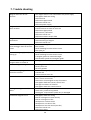
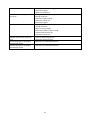
7. Trouble shooting .................................................................................................................... 30
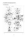
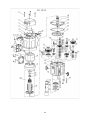
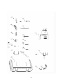
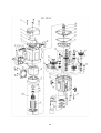
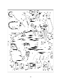
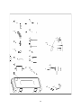
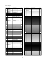
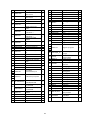
8. Exploded views & spare parts list ............................................................................................ 32
8.1 Exploded views ............................................................................................................................ 32
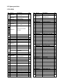
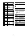
8.2 Spare parts lists ........................................................................................................................... 34
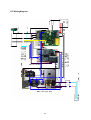
8.3 Wiring diagram ............................................................................................................................ 42
8.4 Warranty and service .................................................................................................................. 43

4
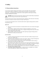
1. Safety
1.1 General safety instructions
Do not use this magnetic drilling machine before you have thoroughly read and completely
understood this manual, specifically the “General safety instructions” and ‘’Specific safety
information’’, including the figures, specifications, safety regulations and the signs indicating
DANGER, WARNING and CAUTION.
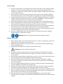
WARNING: When using electrical tools basic safety precautions should always be followed to
reduce the risk of fire, electrical shock and personal injury.
Please also observe the relevant national industrial safety regulations. Non-observance of the safety
instructions can lead to an electric shock, burns and/or severe injuries.
This manual should be kept for later use and enclosed with the magnetic drilling machine, should it
be passed on or sold.
Work area
1. Keep your work area clean and well lit. Cluttered and dark work areas increase the change of
accidents;
2. Do not operate a magnetic drilling machine in explosive atmospheres, such as in the
presence of flammable liquids, gases or dust. A magnetic drilling machine may create sparks
which could ignite the dust or fumes;
3. Keep bystanders, children and visitors away while operating a magnetic drilling machine.
Distractions can cause you to lose control.
Electrical safety
1. A magnetic drilling machine plug must match the outlet. Never modify the plug in any way.
Do not us any adapter plugs;
2. Avoid body contact with grounded surfaces such as pipes, radiators, ranges and refrigerators.
There is an increased risk of electric shock if your body is grounded;
3. Do not expose the magnetic drilling machine to rain or wet conditions. Water entering a
machine will increase the risk of electric shock;
4. Do not abuse the cord. Never use the cord to carry the magnetic drilling machine or pull the
plug from an outlet. Keep the cord away from heat, oil, sharp edges or moving parts. Replace
damaged cords immediately. Damaged cords increase the risk of electric shock;
5. When operating a magnetic drilling machine, use an extension cord suitable for outdoor use,
this reduces the risk of electric shock;
6. If operating a magnetic drilling machine in a damp location is unavoidable, use a residual
current device (RCD), this reduces the risk of electric shock.

5
Personal safety
1. Stay alert, watch what you are doing and use common sense when using a magnetic drilling
machine. Do not use the machine while tired or under the influence of drugs, alcohol, or
medication. A moment of inattention while operating a magnetic drilling machine may result
in serious personal injury;
2. Dress properly. Do not wear loose clothing or jewelry. Keep your hair, clothing and gloves
away from moving parts. Loose clothes, jewelry, or long hair can be caught in moving parts;
3. Avoid accidental starting. Be sure the switch is off before plugging the machine in. Carrying a
magnetic drilling machine with your finger on the switch or plugging in a magnetic drilling
machine that has the switch on increases the change of accidents;
4. Never place hands, fingers, gloves or clothing near drilling area or rotating machine parts;
5. Remove adjusting keys or switches before turning the machine on. A wrench or a key that is
left attached to a rotating part of the machine may result in personal injury;
6. Do not overreach. Keep proper footing and balance at all times. Proper footing and balance
enables better control of the magnetic drilling machine in unexpected situations;
7. Use safety equipment. Always wear eye protection. Dust mask, non-skid safety shoes, hard
hat and hearing protection must be used for optimal safety;
8. Always use supplied safety chain during any work on non-horizontal surfaces. Magnetic
drilling machine can release from surface.
WARNING: Wear ear and eye protection when using this machine.
Machine use and care
1. When using the machine on non-horizontal surfaces, you must use cutting paste. Do not use
oil because the oil can drip into the motor unit;
2. While operating the machine, the annular cutter must be cooled and lubricated with high
quality cutting lubricants;
3. Always remove the slug from the annular cutter after each hole.
CAUTION: The slug is sharp and may be hot!
4. Use clamps or other practical solutions to secure and support the workpiece to a stable
platform. Holding the workpiece by hand or against your body is unstable and may lead to
loss of control;
5. Do not use the machine when the switch does not turn it on or off. Any machine that cannot
be controlled with the switch is dangerous and must be repaired;
6. Disconnect the plug from the power source before making any adjustments, changing
accessories or storing the tool. Such preventive safety measures reduce the risk of starting
the tool accidentally;
7. Store your magnetic drilling machine out of reach for children and other untrained persons.
Tools are dangerous in the hands of untrained users;
8. Maintain your machine with care. Keep cutting tools sharp and clean. Properly maintained
tools, with sharp cutting edges are less likely to break and are easier to control;
9. Check for misalignment of moving parts, breakage of parts and any other condition that may
affect the machine’s operation. If you detect damage have the machine serviced before use.
Many accidents are caused by poorly maintained tools;
10. Only use accessories that are recommended by EUROBOOR for your machine model.
Accessories that are suitable for one machine may become hazardous when used on another
machine.

6
Service
1. Tool service must be performed only by qualified repair personnel. Service or maintenance
performed by unqualified personnel could result in risk of injury;
2. When servicing a tool, use only identical replacement parts. Follow instructions in the
maintenance section of this manual. Use of unauthorised parts or failure to follow
maintenance instructions may create a risk of electric shock or injury;
3. EUROBOOR offers Armature kits containing official EUROBOOR spare parts suitable for your
magnetic drilling machine.
1.2 Specific safety information
• Keep your fingers away from the drilling area;
• Avoid touching the slug that is automatically ejected by the pilot pin when the working
procedure is finished. Contact with the slug when it is hot, or if it falls, can cause personal
injuries;
• Always use the safety guard. Before switching on the machine ensure that the guard is closed
securely;
• Always use the safety chain;
• The magnetic drilling machine is suitable for use on steel with a thickness starting from 6 mm,
with zero air gap between the magnet core surface and the mounting surface. Curvature,
coats of paint and surface irregularities will create an air gap. Keep the air gap to a minimum;
• Always place the machine on a flat surface;
• Do not clamp the magnetic drilling machine on small or irregular shaped objects;
• Always place the machine on a surface that is clear of shavings, chips, swarf and surface dirt;
• Keep the magnet clean and free of debris and swarf;
• Do not switch on the machine before checking whether the magnetic stand has been
tightened firmly to the mounting surface;
• Adjust the machine so cutter does not extend into the workpiece before drilling. Do not
perform any design, assembly or construction activities on the workpiece while the machine is
switched on;
• Before switching on the machine, make sure all accessories have been mounted correctly;
• Do not switch on the machine until it has been mounted and installed according to all above
mentioned instructions;
• Always use the recommended speed for the accessories and material you are working with;
• Do not use the machine on the same workpiece on which electric welders are working;
• Only use an appropriate cutting lubricant. EUROBOOR offers a wide range of well-considered
cooling and lubrication products to match your requirements;
• Do not use liquid cutting fluids while drilling vertically or overhead. Dip the cutter in cutting
paste or apply an appropriate spray for these applications;
• Do not pour cutting fluid into the reservoir while it is mounted in the bracket. Do not allow
cutting fluid to enter the drill motor;
• Before use, ensure movable safety guard operates properly;
• In case of a jammed cutter, turn of the machine, disconnect the machine from the power
supply and then remove the reason for the jam before turning on the machine again.

7
Residual risk
In spite of following the relevant safety regulations and their implementation, certain residual risks
cannot be avoided. These are:
• Impairment of hearing;
• Risk of personal injury from flying particles;
• Risk of burns due to accessories becoming hot during operation;
• Risk of personal injury due to prolonged use.
Always try to reduce these risks as much as possible.

8
2. Description
2.1 Intended use
This magnetic drilling machine is intended for commercial use as a drilling machine for drilling
materials with a magnetisable surface using annular cutters and twist drills, and for countersinking in
a weather-protected environment using the application tools and accessories recommended by
EUROBOOR. The magnetic drilling machine can be used horizontally, vertically or overhead.
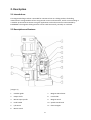
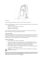
2.2 Description and features
[image 2-1]
1 Gearbox guide
2 Output shaft
3 Morse taper spindle
4 Feed handle
5 L/R switch
6 Motor switch
7 Magnet LED indicator
8 Fuse holder
9 Magnet switch
10 Speed control knob
11 Electromagnet

9
2.3 Case content
1 x ECO.100/4 (D) Magnetic drilling machine
1 x safety guard
3 x handles
1 x hex key 2.5 mm
1 x hex key 4 mm
1 x hex key 5 mm
1 x hex key 6 mm
1 x hex key 8 mm (ECO.100/4 D only)
1 x stop pin
1 x lubrication system
1 x safety chain
1 x bottle (200 ml) of IBO.10 cutting oil
1 x arbor MT 3 - 19.05 mm (3/4"), including lubrication ring
1 x Morse taper ejector drift key
1 x user manual
1 x safety ear protection
1 x safety goggles
1 x safety gloves
2.4 Serial number
The serial number is mentioned on the machine three times: engraved on the frame, engraved on
the magnet and on the serial no. sticker on the motor housing. Additional serial no. stickers are
provided with the machine for your administration.
The serial number will help you, your dealer and EUROBOOR to validate and identify the machine.
For example:
1002006001
breaks down to:
100 20 06 001
Machine series
Year of manufacture
Month of manufacture
Identification number

10
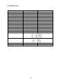
2.5 Technical data
Metric
Imperial
Annular cutting
Ø 12
-
100 mm
Ø
1/2
"
-
13 15/16"
Twist drilling
Ø 1
-
31.75 mm
Ø
1/16
"
-
1 1/4
"
Threading
M3
-
M30
1/8"
-
1 3/16"
Countersinking
Ø 10
-
105 mm
Ø
3/8
"
-
4 1/8
"
L
ength
365
mm
14 3/8
"
Width
310
mm
12 3/16
"
Height (ECO.100
/4
)
5
10
-
710
mm
20 1/16
"
-
27
15/16"
Height (ECO.100
/4
D
)
5
1
9
-
7
1
9
mm
2
0
7/16
"
-
28
5
/
16
"
Stroke
260
mm
10 1/4
"
Weight
(ECO.100/4)
28.
0
kg
6
1
.
7
lbs
Weight (ECO.100/4 D)
31.2 kg
68.
8 lbs
Mag
net (l x w x h)
220
x
110
x
64
mm
8 11/16
"
x
4 5/16
"
x
2 1/2
"
Magnetic force
3,000
kg
6,614
lbs
Motor power
1,900 W
15.5 A
Total power
2,050
W
16.7 A
Speed (no load)
(I)
42
-
110 rpm
(II) 65 - 190 rpm
(III) 140 - 400 rpm
(IV) 220 - 620 rpm
Speed (
1,900 W
load)
(I)
85
rpm
(II) 152 rpm
(III) 270 rpm
(IV) 480 rpm
Spindle (Weldon)
MT3 19.05
mm
MT3 3/4"
Voltage
220
-
240 V / 5
0
-
6
0
Hz
110
-
1
2
0 V / 6
0
Hz

11
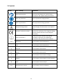
2.6 Symbols
Symbol Term, meaning Explanation
Read documentation
Be sure to read the documentation in this user
manual and specifically the “General safety
instructions” and ‘’Specific safety information’’
Wear ear protection
Use ear protection during operation
Wear eye protection
Use eye protection during operation
Danger/warning/caution
Read and apply the information in the adjacent
text!
European conformity symbol
Confirms the conformity of the magnetic drilling
machine with the directives of the European
Community
Class of protection I
Product with basic insulation and exposed
(touchable) conductive parts additionally
connected to the protective earth conductor
mm
Millimeter
Unit of measure for the dimensions
"
Inch
Unit of measure for the dimensions
kg
Kilogram
Unit of measure for the mass
lbs
Pound
Unit of measure for the mass
V
Volt
Unit of measure for the electric voltage
A
Ampere
Unit of measure for the electric current intensity
W
Watt
Unit of measure for the output
rpm
Revolutions per minute
Unit of measure for the revolutions

12
2.7 Environmental
Separate collection. This product must not be disposed of with normal household waste.
Separate collection of used products and packaging allows materials to be recycled and used
again. Re-use of recycled materials helps prevent environmental pollution and reduces the
demand for raw materials.
Local regulations may provide for separate collection of electrical products from the household, at
municipal waste sites or at the retailer when you purchase a new product.

13
3.
Preparation & adjustment
3.1 Assembly
WARNING: To reduce the risk of injury, turn machine off and disconnect from power source
before installing and removing accessories, before adjusting or changing set- ups or when
making repairs. Be sure all switches are in the OFF position. An accidental start-up can cause
injury.
Fitting the feed handles
Fit each of the three feed handles by screwing them into the hub in clockwise direction;
Tighten firmly by hand.
The handles are supposed to face slightly outward. Be careful not to cross-thread any of the
components.
Mounting the safety guard
The safety guard protects against chippings and accidental contact and must always be mounted
before operation:
1. Hold the guard in front of the magnet, align the slots in the guard with the holes in the
magnet;
2. Fit the screws into the holes located in the side of the magnet.
WARNING: Always use the safety guard.
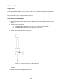
Fitting the lubrication system
The lubrication system can only be used for horizontal drilling
(the drill being used vertically).
1. Hang the tank on the tank holder;
2. Position and tighten the attachment pin;
3. Connect the hose to the fitting on the gearbox. Make sure
the hose is connected fully and tightly;
4. To disconnect the hose, press the blue ring on the connection
and gently pull out the hose.
[image 3-1]
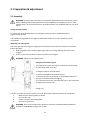
In order to use the lubrication system, it must be filled with a sufficient amount of cutting fluid.
1. Make sure the flow regulator is closed;
2. Unscrew the cap;
3. Fill the container with cutting fluid;
4. Screw the cap back on.
WARNING: Do not use the lubrication system in vertical or overhead drilling applications.
Instead use EUROBOOR cutting paste or spray.

14
Fitting the safety chain
1. Pass the safety chain through the frame grip opening;
2. Wrap the chain around the workpiece;
3. Securely close the chain using the lock.
WARNING: Always use the safety chain when drilling vertically and/or upside down. The
safety chain does not replace the magnetic force of the magnetic drilling machine: it is simply
used to secure against falling in the event of a magnet malfunction.
3.2 Prior to use
Please make sure that the contacting surface for the magnet is level, clean and rust free.
Remove any varnish or primer. When working on materials that are not magnetisable, suitable
fixation devices, obtainable as accessories from EUROBOOR, e. g. suction plate, vacuum plate or
pipe-drilling machine must be used.
When working on steel materials with a material thickness of less than 6 mm, the workpiece must
be reinforced with an additional steel plate in order to guarantee the magnetic holding power.
Check the machine for possible damage; Before using the machine, you must carefully check the
protective components or slightly damaged components to ensure they are operating perfectly and
as intended.
Check that moving parts are in perfect working order, do not jam and check whether the parts are
damaged. All parts must be correctly installed and fulfill all conditions necessary to ensure perfect
operation of the machine.
Damaged protective components must be repaired or replaced according to specifications by
EUROBOOR or any authorised EUROBOOR dealer.
DO NOT use under wet conditions or in presence of flammable liquids or gases.
DO NOT let children come into contact with the machine. Supervision is required when
inexperienced operators use this machine.
Electrical safety
The electric motor has been designed for one voltage only. Always check that the power supply
corresponds to the voltage on the rating plate.
Your EUROBOOR magnetic drilling machine is designed in class I (grounded) according to EN 61029-1.
Earth wire is required.
If the supply cord is damaged, it must be replaced by a specially prepared cord available at
EUROBOOR or your EUROBOOR dealer.
Extension cable
If an extension cable is required, use an approved 3-core extension cable suitable for the power input
of this machine (see technical data).The minimum conductor size is 1.5 mm²; the maximum length is
30 metre. When using a cable reel, always unwind the cable completely.

15
Useful tips
– Try a few simple projects using scrap material until you develop a ‘’feel’’ for the magnetic
drilling machine;
– Let the machine run in for a period of eight to ten hours before starting with big operations.
Do not load the machine too much during this run-in period;
– Never use the machine with serious overload;
– Keep the machine clear from moisture at all times to protect the machine, yourself and
others.
.

16
4. Using the machine
WARNING: Always observe the safety instructions and applicable regulations.
WARNING: To reduce the risk of serious personal injury, turn the machine off and disconnect
the machine from power source before making any adjustments or removing/installing
attachments or accessories.
4.1 Control panel
The control panel on your magnetic drilling machine is designed for maximum ease of use and safety.
1. Magnet switch
2. Speed control knob
3. Fuse holder
4. Magnet LED indicator
5. Motor switch
6. L/R switch
4.2 Electromagnet
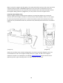
Make sure the magnetic drilling machine is placed on a smooth, clean, level and solid surface without
any objects or debris to guarantee maximum adhesion.
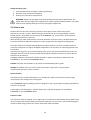
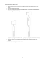
The workpiece must at least be 6 mm (1/4") thick for the magnet to stick and to drill safely. In case
the workpiece is between 3 mm (1/8") and 6 mm (1/4"), make sure to make a proper base to create
a good magnetic field as shown below.
[image 4
-
1]

17
[image 4-2]
The electromagnet will work best on surfaces of at least 10 mm (3/8") thickness.
When the electromagnet is not able to create a good enough magnetic field, this may be caused by:
- Surface not being flat;
- Workpiece is not magnetisable (e.g. aluminium);
- Workpiece is coated or painted;
- Workpiece is not thick enough.
In this situation the magnet indicator will light up red. Make sure to solve any of these matters
before proceeding in any way and creating unsafe situations.
2-Way electromagnet
This machine is equipped with a 2-way magnet function. At half of the magnetic force (1,500 kg), the
magnet sufficiently sticks to the surface to hold the machine in position while not in use. More
importantly, it consumes less energy, generates less heat and as a consequence will last longer. Only
with full magnetic force (3,000 kg) the machine can be used for drilling.
Using the 2-way magnet:
1. Place and position the machine on the workpiece;
2. To activate the magnet at half of the magnetic force, press the RED magnet switch. The
magnet switch will be lit. The magnet LED indicator lights up GREEN when the generated
magnetic force is sufficient to hold the machine in position while not drilling;
3. For full magnetic force, press the GREEN motor switch (see next paragraph);
4. To deactivate the magnet, first press the RED motor switch to return to half magnetic force
and then press the RED magnet switch again.
WARNING: Do not use this machine when LED indicator is RED. Magnet may not generate
sufficient attachment force.
We want to point out that above mentioned precautions and indicators do not guarantee that the
magnet will not release from the material. EUROBOOR accepts no liability when it comes to the
magnet indicator not functioning or functioning poorly.

18
Make sure that the magnet attaches tightly to the work piece before turning on the motor unit of the
magnetic drilling machine. EUROBOOR magnets have two coils; make sure that both coils are in
contact with the material. Do not connect any other machine to the same electrical outlet to which
the magnetic drilling machine is plugged into, as it may result in the loss of magnetic force.
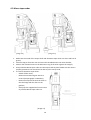
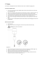
Swivel base (ECO.100/4 D only)
With the magnet properly attached to the workpiece, the swivel base allows you to rotate the
machine 30⁰ to left and right, and slide it 15-20 mm forward and backwards, relative to the magnet,
for more precise positioning of the drill. To swivel the machine, loosen the screw below the frame
handle with the provided 8 mm Allen key. Determine the preferred position and fix the screw before
drilling.
[image 4-3] [image 4-4]
Always use the safety chain included. Drilling above your head is extremely dangerous and is not
recommended. For the use of magnetic drilling machines on pipes, not-flat or non-magnetic
materials, we refer to our catalogue or our website www.euroboor.com where several vacuum
tightening systems, pipe clamping systems and Tube machines can be found.

19
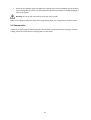
4.3 Morse taper arbor
[image 4.5] [image 4.6]
1. Make sure the inside of the output shaft and the Morse taper arbor are clean and free of
grease;
2. Take the stop pin from the case and screw the threaded end in the motor bracket;
3. Position the rotation limiter on the lubrication ring of the arbor against the stop pin;
4. Firmly slide the Morse taper arbor into the output shaft by hand. Make sure the arbor is
properly positioned. You should not be able to pull it out by hand;
5. To remove the Morse taper arbor:
- Switch off the motor;
- Rotate the mechanical gear switch to
neutral (see paragraph 4.4 Gearbox);
-
Rotate the output shaft until the slots on
the shaft align with the slots on the
gearbox;
-
Gently tap the supplied drift into the slots
to push the Morse taper arbor out.
[image 4.7]

20
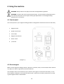
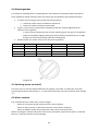
4.4 Manual gearbox
This machine is equipped with a 4-speed gearbox. Gear switches on both sides make it possible to
select 4 different speeds manually. Select the closest gear and speed for the intended operation.
1. To select the correct gear from neutral (horizontal) position:
a. Rotate the switch counter clockwise to position o;
b. Rotate the switch clockwise to position oo.
2. A gear is only correctly selected when the gearbox switches are both aligned with the
indicators on the gearbox:
In case you have trouble fully and correctly selecting a gear, the gears in the gearbox
might be misaligned. Slightly rotating the output shaft by hand will help you to align
the gears and correctly and fully select the intended gear;
3. Speed selection for annular cutters (also see plate on gearbox):
Front switch
Back swi
tch
Speed
Cutter Ø
Cutter Ø
o
oo
42
-
110 rpm
12
-
26 mm
1/2"
-
1"
oo
oo
66
-
190 rpm
27
-
50 mm
1
1
/16"
-
2
"
o
o
140
-
400 rpm
51
-
79 mm
2"
-
3 1/8
"
oo
o
220
-
620 rpm
80
-
100 mm
3
1
/
8
"
-
3
15
/
1
6
"
[image 4-8]
4.5 Switching motor on and off
The motor unit can only be switched ON when the magnet is activated. To switch the motor ON,
press the green button with marking “I”. To switch the motor OFF, press the red button with marking
“O”.
4.6 Motor rotation
The rotational direction of the motor can be changed:
- Switch in up position (R) will make the motor rotate clockwise;
- Switch in down position (L) will make the motor rotate counter clockwise;
- Switch in middle position will not make the motor rotate (neutral position).
Before switching the rotational direction of the motor and spindle, make sure the motor is switched
OFF first, to prevent machine and tool damage.
Page is loading ...
Page is loading ...
Page is loading ...
Page is loading ...
Page is loading ...
Page is loading ...
Page is loading ...
Page is loading ...
Page is loading ...
Page is loading ...
Page is loading ...
Page is loading ...
Page is loading ...
Page is loading ...
Page is loading ...
Page is loading ...
Page is loading ...
Page is loading ...
Page is loading ...
Page is loading ...
Page is loading ...
Page is loading ...
Page is loading ...
-
 1
1
-
 2
2
-
 3
3
-
 4
4
-
 5
5
-
 6
6
-
 7
7
-
 8
8
-
 9
9
-
 10
10
-
 11
11
-
 12
12
-
 13
13
-
 14
14
-
 15
15
-
 16
16
-
 17
17
-
 18
18
-
 19
19
-
 20
20
-
 21
21
-
 22
22
-
 23
23
-
 24
24
-
 25
25
-
 26
26
-
 27
27
-
 28
28
-
 29
29
-
 30
30
-
 31
31
-
 32
32
-
 33
33
-
 34
34
-
 35
35
-
 36
36
-
 37
37
-
 38
38
-
 39
39
-
 40
40
-
 41
41
-
 42
42
-
 43
43


Euroboor ECO.100/4D Owner's manual
- Type
- Owner's manual
- This manual is also suitable for
Ask a question and I''ll find the answer in the document
Finding information in a document is now easier with AI
Related papers
-
Euroboor ECO.80S+ User manual
-
-
-
-
-
-
-
-
-
Other documents
-
DeWalt DWE1622 User manual
-
Walter ICECUT MINI Owner's manual
-
-
 Rotabroach SMARTPANTHER1 User manual
-
 Unibor UA5000 Operating Instructions Manual
-
Ronix 2211V User manual
-
-
Metabo MAG 50 Operating instructions
-
 Nitto Kohki ATRA ACE AO-5575 User manual
-
 Itm HMPRO35 User manual


