Watts PWD020AFAX Installation guide

Category
Sanitary ware
Type
Installation guide
This device complies with part 15 of the FCC Rules. Operation
is subject to the following two conditions: (1) This device may
not cause harmful interference, and (2) this device must accept
any interference received, including interference that may cause
undesired operation.
This device complies with Industry Canada licence-exempt RSS
standard(s). Operation is subject to the following two condi-
tions: (1) this device may not cause interference, and (2) this
device must accept any interference, including interference that
may cause undesired operation of the device.
Lé present appareil est conforme aux CNR d'Industrie
Canada applicables aux appareils radio exempts de licence.
L'exploitation est autorisée aux deux conditions suivantes : (1)
l'appareil ne doit pas produire de brouillage, et (2) l'utilisateur
de l'appareil doit accepter tout brouillage radioélectrique subi,
même si le brouillage est susceptible d'en compromettre le
fonctionnement.
Any changes or modifications of this product not approved by
the manufacturer could void the user’s authority to operate the
equipment.
This equipment complies with IC RSS-102 radiation exposure
limits set forth for an uncontrolled environment. This equipment
should be installed and operated with minimum distance 20cm
between the radiator & your body.
Under Industry Canada regulations, this radio transmitter may
only operate using an antenna of a type and maximum (or
lesser) gain approved for the transmitter by Industry Canada. To
reduce potential radio interference to other users, the antenna
type and its gain should be so chosen that the equivalent iso-
tropically radiated power (e.i.r.p.) is not more than that neces-
sary for successful communication.
IOM-PW-SmartStream-C_D
Installation Precautions ...................................3
System Specifications . . . . . . . . . . . . . . . . . . . . . . . . . . . . . . . . . . 4-7
Product Specification Tables ............................. 5-7
Dimensions ............................................8
Feed Water Requirements .................................9
Installation Procedure ................................. 9-10
Maintenance ..........................................11
Lamp and Quartz Sleeve Replacement ......................11
Disinfection Procedure...................................11
Parts List .......................................... 12-13
Troubleshooting........................................14
Controller Identification ..................................15
Overview of Screens ................................. 16-20
Controller Wiring .......................................21
Warranty and Conditions .................................24
Table of Contents
Original Instructions
Read this Manual BEFORE using this
equipment. Failure to read and follow
all safety and user information can
result in death, serious personal injury,
property damage, or damage to the equipment.
Keep this Manual for future reference.
WARNING
!
This system contains a UV-C emitter (UV lamp)
DO NOT look directly at the UV lamp while it
is ON. Permanent serious eye damage could
occur.
DO NOT use if UV lamp, housing or any part of
system is damaged.
Any damage to UV lamp or misuse of system
could result in escape of dangerous UV-C radia-
tion. UV-C radiation even in small doses can
cause harm to eyes and skin.
NEVER use UV lamp if it is removed from the
housing (enclosure).
ALWAYS turn OFF and disconnect (unplug) sys-
tem from power supply BEFORE replacing UV
lamp or performing any repairs or maintenance.
WARNING
!
Installation, Operation and
Maintenance Manual
254 Nanometer Germicidal
UV Disinfection Systems
Models
PWC012 PWC016 PWC020 PWC025 PWC040 PWC050
PWD012 PWD016 PWD020 PWD025 PWD040 PWD050
SmartStream
UV
Chemical Free Disinfection of Water
SmartStream UV is certified by the Water Quality
Association (WQA) to NSF/ANSI Standard 372
for lead free.
UV
2
Introduction
Thank you for purchasing the Watts SmartStream™ line of ultra-
violet disinfection systems. SmartStream™ provides protection
against microbiological contamination in water for residential and
commercial applications. Disinfection of water with SmartStream™
is a simple, rapid physical process. When contaminated water is
exposed to SmartStream's™ 254 nanometer UV light, the UV light
penetrates the cell walls of microorganisms, disrupts their genetic
deoxyribonucleic acid (DNA) material, and quickly inactivates mi-
croorganisms by destroying their ability to replicate and infect. This
device conforms to the applicable provisions of the Code of Federal
Regulations (CFR) requirements including, Title 21, Chapter 1, Sub-
chapter J, Radiological Health.
SmartStream™ will provide safe and productive operation as long
as it is used in accordance with the instructions in this manual and
is properly maintained by adequately trained and supervised people.
Owners should not permit anyone to touch this equipment unless
they are over 18 years of age, are adequately trained and super-
vised, and have read and understand this manual. Owners should
also ensure that no unauthorized personnel come in contact with
this equipment. READ THIS MANUAL carefully, learn how to use
and service this equipment correctly, and strictly follow all of the
instructions contained in this manual and the requirements of local,
state and federal law. This manual should be considered a perma-
nent part of your machine and should be kept available for easy
reference by any user.
If this equipment, or any of its parts, becomes damaged or needs
repair, stop using the equipment and contact an experienced ser-
vice individual immediately. If the warning labels or this manual are
misplaced, damaged or illegible, or if you require additional copies,
please contact customer service at _________ for these items at no
charge.
If you are ever uncertain about a particular task or the proper
method of operating this equipment, ask your supervisor, consult
this manual, access www.___________.com, or contact us at
_____________________.
Product Identifi cation
Model: Date of purchase:
Serial #: Date of Installation:
Please record your product’s identifi cation and purchase information
which will help in the event you have questions or need any service.
ect.
This system should only be installed and maintained by a qual-
ifi ed professional. Observe all national, state, and local plumb-
ing and building codes when installing the system.
NOTICE
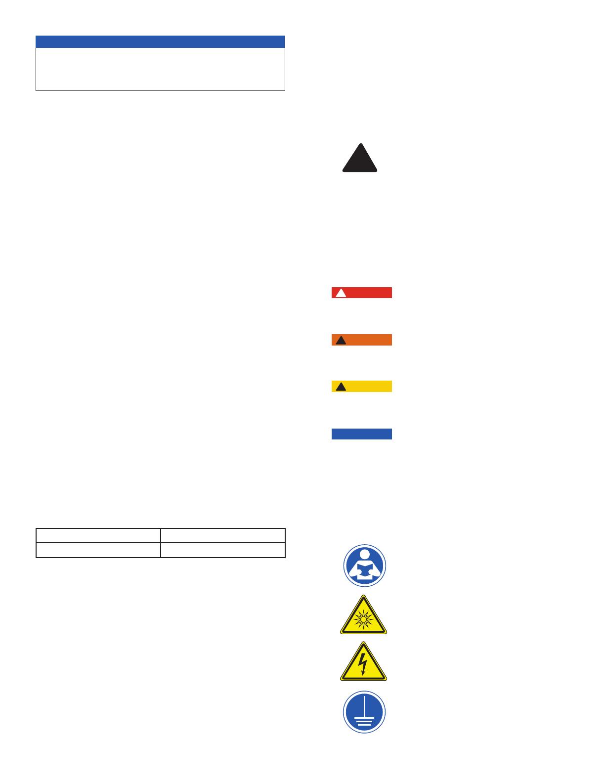
Understanding Safety Information
This manual contains safety and use instructions that must be
followed during the installation, commissioning, operation, care
and maintenance, and service of the SmartStream™. All respon-
sible personnel must read this manual prior to working with this
instrument, and should familiarize themselves with the following
safety symbols, signals, and pictorials.
This is a safety-alert symbol. The
safety alert symbol is shown alone or
used with a signal word (DANGER,
WARNING, or CAUTION), a pictorial
and/or a safety message to identify
hazards.
When you see this symbol alone or with
a signal word on your equipment or in
this Manual, be alert to the potential for
death or serious personal injury.
This symbol identifies hazards which, if
not avoided, will result in death or seri-
ous injury.
This symbol identifies hazards which,
if not avoided, could result in death or
serious injury.
This symbol identifies hazards which,
if not avoided, could result in minor or
moderate injury.
This symbol identifies practices, actions,
or failure to act which could result in
property damage or damage to the
equipment.
This pictorial alerts you to the need to
read the Manual.
This pictorial alerts you to electricity,
electrocution and shock hazards.
This pictorial alerts you to Ultraviolet
(UV) hazards
This pictorial alerts you to connect the
System only to a properly grounded
receptacle protected by a Ground Fault
Circuit Interrupter (GFCI)
WARNING
!
CAUTION
!
NOTICE
DANGER
!
!
Safety signal words have the following meaning:
Pictorials used on the equipment and in this
Manual have the following meanings:
UV
3
Watts SmartStream
UV systems are engineered with the high-
est quality components. If at anytime a component needs to be
replaced, use only parts recommended and supplied by Watts.
DO NOT add components to or remove components from this
system.
The UV lamp is rated for 9000 hours under normal operating
conditions and should be replaced annually to keep the UV
intensity at the highest possible output. Quartz sleeves should
be cleaned as needed or replaced as needed to guarantee the
highest possible UV transmittance into the water.
Use only Watts supplied UV lamps and quartz sleeves for your
specific model. Failure to do so may result in system failure and
will void all warranty.
DO NOT use this system in a manner that it is not intended for.
This purifier is only for use in water applications where the feed
water, installation environment and installation method meets
the requirements within this manual.
The system must be properly sized. DO NOT exceed the rated
flow rate capacity of the system. Flow controllers are available
from Watts to ensure system's rated flow is not exceeded.
Follow all product safety labeling.
DO NOT let the system freeze. System damage may result.
Install the system on a flat, and level surface.
The quality of the water to be treated must meet the feed
water guidelines within this manual. Failure to ensure proper
pretreatment will result in inadequate disinfection.
NOTICE
Using SmartStream
with other water treatment equipment
SmartStream
UV units can be installed as a final disinfection
method within a water treatment system train or as pretreat-
ment to protect sensitive components, such as reverse osmo-
sis membranes, from bio-films.
The injection of chemicals into the water should be done on the
outlet of the SmartStream
system to ensure UV light degrada-
tion of the chemical or the introduction of turbidity within the UV
feedstream does not occur.
A 5 micron particle filter should always be installed immediately
before the SmartStream
system.
Be certain that the feed water meets all criteria within the Feed
Water Specifications section of this manual.
This appliance can be used by people aged from 18 years and
above and persons with reduced physical, sensory or mental
capabilities or lack of experience and knowledge if they have
been given supervision or instruction concerning use of the
appliance in a safe way and understand the hazards involved.
Children shall not play with the appliance. Cleaning and user
maintenance shall not be made by children.
NOTICE
DO NOT rely solely on this system to make water safe to drink.
SmartStream
UV disinfection systems are intended to be used
as part of a well designed water treatment system. Water that
contains microbiological contamination should be tested regu-
larly to ensure its quality and safety at the point of use.
DO NOT touch the quartz sleeve with your fingers. Hold it with
a paper towel.
DO NOT touch the lamp with your fingers. Hold it with
a paper towel.
WARNING
!
WARNING
!
WARNING
!
WARNING
!
This device conforms to the applicable provisions of the Code
of Federal Regulations (CFR) requirements including, Title 21,
Chapter 1, Subchapter J, Radiological Health.
4
System Specifications
C- Basic controller with lamp dimming, flow switch, lamp out au-
dible alarm, multicolor LED system status indicator, glow cap lamp
indicator, lamp life timer with 3 digit LED display, radio frequency
communication to lamps to verify correct lamps and remaining life
of the lamp. Lamp life timer resets when a new lamp is inserted.
Includes alarm output for solenoid valve, UV sensor input, 4-20 mil-
liamp output for UV Intensity (When UV Sensor is used).
C Series controllers are certified by the Federal Communications
Commission (FCC) listed under identification number
FCC ID: 2AFJT-SMARTSTREAM and Industry Canada (IC) listed
under identification number IC: 20623-SMARTSTREAM.
D- All features of the C controller. The display changes from a 3
digit LED display to a graphic touch screen. Total system hours are
displayed along with key operational data.
D Series controllers are certified by the Federal Communications
Commission (FCC) listed under identification number
FCC ID: 2AFJT-SMARTSTREAM and Industry Canada (IC) listed
under IC: 20623-SMARTSTREAM.
Controller Features
Two different controllers are available on various SmartStream
UV
systems. The controllers are identified as "C" or "D" series. Each
controller has unique features and are outlined as follows:
Model C Model D
SmartStream
UV System Part Number Identification Key
Prefix "W" "Controller Series" "GPM" "Connection Type" "Pipe Size" "Plug" "Accessories"
Watts Controller Type
C: Controller C
D: Controller D
GPM of System
(3-Digits)
Connection Port
Types:
A: NPT
B: BSP-Tapered
Pipe Size
B: 3/8"
C: 1/2"
D: 3/4"
E: 1"
F: 3/4" Female X 1"
Male Combination
Fitting
G: 1" Female X 1 1/2"
Male Combination
Fitting
A: North American
B: European
C: British U.K.
D: Australian
Accessories
X: No Accessories
(Accessories only
available for systems
using the C and D
type controllers.)
A: UV Sensor
Installation Guidelines
DO NOT allow this system to remain ON without water in it
for extended periods of time.
DO NOT install the system near any source of heat. Also, DO
NOT install the system near any device or break out area that
would be adversely effected by water.
DO NOT install this system higher in elevation than 10,000
feet above sea level.
DO NOT install the system backwards with the feed water
line connected to the outlet.
DO NOT install where system is exposed to harsh chemicals
or may be subjected to being struck by moving equipment,
carts, mops or any other item that may cause damage.
DO NOT install the system outdoors. Keep system away from
moisture, rain, and direct sunlight. Ambient air temperature
must remain below 122°F and relative humidity must remain
below 95%.
DO NOT allow the system to freeze.
The system MUST be mounted on a surface and with mount-
ing hardware that is sturdy enough to support the weight of
the wetted system.
The system MUST be plugged into an uninterrupted power sup-
ply that matches the rated power requirement of the system. In
European installations, the appliance is to be supplied through a
residual current device (RCD) having a rated residual operating cur-
rent not exceeding 30 milliamps.
The system MUST be installed in accordance with all appli-
cable national, state and local codes.
A prefilter with a 5 micron minimum particle size reduction
must be installed on the inlet line to the system. Additional
pretreatment may be necessary so that the feedwater con-
forms to the Feed Water Specifications section on page 8.
Plumbing materials sensitive to UV light, typically plastic
materials, should not be connected directly to the system. To
prevent UV degradation at the plumbing connection points
on the system, use one foot minimum of copper or stainless
steel plumbing material to connect to the inlet and to the out-
let of the system.
IF water hammer is evident, install water hammer arrestors
before the system.
Always back-up valves and fittings with a wrench when con-
structing plumbing to reduce unnecessary stress on the sys-
tem and its plumbing.
Position the system in a suitable location. Make sure there is
enough clearance between the end of UV chamber and any ob-
structions, to allow for the removal of the lamp and quartz sleeve.
SmartStream
UV disinfection systems should be installed as close
as possible to the treated water's point of use.
WARNING
!
5
System Features
C Series Controller With Lamp Dimming
FCC ID: 2AFJT-SMARTSTREAM GPM Rating 12 16 20 25 40 50
IC: 20623-SMARTSTREAM System Model # PWC012 PWC016 PWC020 PWC025 PWC040 PWC050
Universal Power Input
4 4 4 4 4 4
316 SS Chamber
4 4 4 4 4 4
Audible Alarm
4 4 4 4 4 4
Lamp On Indicator
4 4 4 4 4 4
Glow Cap Lamp Indicator
4 4 4 4 4 4
Lamp Life Timer with 3-digit display
4 4 4 4 4 4
Automatic Lamp Shut Off when
Removed from the Chamber (wireless)
4 4 4 4 4 4
Lamp Dimming
4 4 4 4 4 4
Integrated Bracket Mounting
4 4 4 4 4 4
Alarm Contact Relay (for solenoid valve)
4 4 4 4 4 4
UV Sensor Input
4 4 4 4 4 4
4-20 mA Output (If UV Sensor is used)
4 4 4 4 4 4
12V Power for Chamber Cooling Fan
4 4 4 4 4 4
Graphic Display
Total System Hours Indicator
Product Specifications Table
MODEL PWC012
PWC016 PWC020 PWC025 PWC040 PWC050
FLOW RATE @ 16mJ
(95%UVT @ EOL)
(may be hydraulically limited)
usgpm
liters/min
24.0 gpm
90.8 lpm
31.5 gpm
119.2 lpm
39.0 gpm
147.6 lpm
46.9 gpm
177.5 lpm
75.0 gpm
283.9 lpm
93.8 gpm
355.0 lpm
FLOW RATE @ 30mJ
(95%UVT @ EOL)
usgpm
liters/min
12.8 gpm
48.4 lpm
16.8 gpm
63.6 lpm
20.8 gpm
78.7 lpm
25.0 gpm
94.6 lpm
40.0 gpm
151.4 lpm
50.0 gpm
189.3 lpm
FLOW RATE @ 40mJ
(95%UVT @ EOL)
usgpm
liters/min
9.6 gpm
36.3 lpm
12.6 gpm
47.7 lpm
15.6 gpm
59.0 lpm
18.8 gpm
71.2 lpm
30.0 gpm
113.6 lpm
37.5 gpm
141.9 lpm
STANDARD NPT INLET / OUTLET PORTS
1"NPT-M / 3/4"NPT-F
Combo Ports
1.5"NPT-M / 1"NPT-F
Combo Ports
OPTIONAL BSP-T INLET / OUTLET
PORTS
1"BSP-M / 3/4"BSP-F
Combo Ports
1.5"BSP-M / 1"BSP-F
Combo Ports
CHAMBER MATERIAL 316L SS
CONTROLLER MOUNTING On chamber bracket or remote from chamber
INPUT VOLTAGE 100 to 240VAC 50/60Hz
SYSTEM MAX NOMINAL INPUT POWER
(Watts)
47 58 67 67 100 118
LAMP MAX NOMINAL ELECTRICAL
POWER (Watts)
45 55 64 64 95 112
LAMP TECHNOLOGY
Quartz glass low pressure lamp / ozone free / true pre-heat starting / glow-cap indicator
WIRELESS LAMP KEY Standard
LAMP DIMMING / FLOW SWITCH Standard
CHAMBER COOLING FAN Applicable Option
SYSTEM DISPLAY TYPE Seven segment three digit LED
LAMP LIFE MONITOR 3-digit LED Display, auto-reset with new lamp
UV SENSOR Available Option
4-20mA OUTPUT With UV Sensor Option
VISUAL ALARM Multi-color status LED
AUDIBLE ALARM Yes
AUDIBLE ALARM MUTE Yes
ALARM RELAY / SOLENOID CONTACTS Yes - 24V 5 Amp Maximum
ALARM RELAY MANUAL OVER-RIDE Yes
MAXIMUM AMBIENT AIR TEMPERATURE / HUMIDITY 50°C ( 122°F) / 95% RH (non-condensing)
INLET WATER TEMPERATURE RANGE 34°F ( 1°C) to 113°F ( 45°C)
MAX WATER PRESSURE 125psi (861 kPa)
SHIPPING WEIGHT
19LB (9KG) 19LB (9KG) 20LB (9KG) 25LB (11KG) 27LB (12KG) 29LB (13KG)
6
Product Specifications Table
MODEL PWD012
PWD016 PWD020 PWD025 PWD040 PWD050
FLOW RATE @ 16mJ
(95%UVT @ EOL)
(may be hydraulically limited)
usgpm
liters/min
24.0 gpm
90.8 lpm
31.5 gpm
119.2 lpm
39.0 gpm
147.6 lpm
46.9 gpm
177.5 lpm
75.0 gpm
283.9 lpm
93.8 gpm
355.0 lpm
FLOW RATE @ 30mJ
(95%UVT @ EOL)
usgpm
liters/min
12.8 gpm
48.4 lpm
16.8 gpm
63.6 lpm
20.8 gpm
78.7 lpm
25.0 gpm
94.6 lpm
40.0 gpm
151.4 lpm
50.0 gpm
189.3 lpm
FLOW RATE @ 40mJ
(95%UVT @ EOL)
usgpm
liters/min
9.6 gpm
36.3 lpm
12.6 gpm
47.7 lpm
15.6 gpm
59.0 lpm
18.8 gpm
71.2 lpm
30.0 gpm
113.6 lpm
37.5 gpm
141.9 lpm
STANDARD NPT INLET / OUTLET PORTS
1"NPT-M / 3/4"NPT-F
Combo Ports
1.5"NPT-M / 1"NPT-F
Combo Ports
OPTIONAL BSP-T INLET / OUTLET PORTS
1"BSP-M / 3/4"BSP-F
Combo Ports
1.5"BSP-M / 1"BSP-F
Combo Ports
CHAMBER MATERIAL 316L SS
CONTROLLER MOUNTING On chamber bracket or remote from chamber
INPUT VOLTAGE 100 to 240VAC 50/60Hz
SYSTEM MAX NOMINAL INPUT POWER
(Watts)
47 58 67 67 100 118
LAMP MAX NOMINAL ELECTRICAL
POWER (Watts)
45 55 64 64 95 112
LAMP TECHNOLOGY
Quartz glass low pressure lamp / ozone free / true pre-heat starting / glow-cap indicator
WIRELESS LAMP KEY Standard
LAMP DIMMING / FLOW SWITCH Standard
CHAMBER COOLING FAN Available Option
SYSTEM DISPLAY TYPE Color Touch Screen with multiple languages, intuitive screen navigation, detailed
system status messages, maintenance/diagnostic, and dealer programmable
with website/contact information/QR codes
LAMP LIFE MONITOR Display on graphic touch screen, auto-reset with new lamp
UV SENSOR Available Option
4-20mA OUTPUT With UV Sensor Option
VISUAL ALARM Animated icons and text messages on graphic display
AUDIBLE ALARM Yes
AUDIBLE ALARM MUTE Yes
ALARM RELAY / SOLENOID CONTACTS Yes- 24V 5 Amp Maximum
ALARM RELAY MANUAL OVER-RIDE Yes
MAXIMUM AMBIENT AIR TEMPERATURE / HUMIDITY 50°C ( 122°F) / 95% RH (non-condensing)
INLET WATER TEMPERATURE RANGE 34°F ( 1°C) to 113°F ( 45°C)
MAX WATER PRESSURE 125psi (861 kPa)
SHIPPING WEIGHT
19LB (9KG) 19LB (9KG) 20LB (9KG) 25LB (11KG) 27LB (12KG) 29LB (13KG)
System Features
D Series Controller With Lamp Dimming and Graphics Display
FCC ID: 2AFJT-SMARTSTREAM GPM Rating 12 16 20 25 40 50
IC: 20623-SMARTSTREAM System Model # PWD012 PWD016 PWD020 PWD025 PWD040 PWD050
Universal Power Input
4 4 4 4 4 4
316 SS Chamber
4 4 4 4 4 4
Audible Alarm
4 4 4 4 4 4
Lamp On Indicator
4 4 4 4 4 4
Glow Cap Lamp Indicator
4 4 4 4 4 4
Lamp Life Timer with 3-digit display
4 4 4 4 4 4
Automatic Lamp Shut Off when
Removed from the Chamber (wireless)
4 4 4 4 4 4
Lamp Dimming
4 4 4 4 4 4
Integrated Bracket Mounting
4 4 4 4 4 4
Alarm Contact Relay (for solenoid valve)
4 4 4 4 4 4
UV Sensor Input
4 4 4 4 4 4
4-20 mA Output (if UV Sensor is used)
4 4 4 4 4 4
12V Power for Chamber Cooling Fan
4 4 4 4 4 4
Graphic Display
4 4 4 4 4 4
Total System Hours Indicator
4 4 4 4 4 4
7
Dimensions
All dimensions are in inches.
* Allow this amount of overhead clearance for
the removal of lamp and quartz sleeve.
NOTICE
Controller Mounted on Chamber- 12 to 50 GPM
GPM A B C D E F G H I
12 3.34 23.92 24.95 7.63 8.29 3.00 4.50 16.00 22.00
16 3.34 27.86 28.89 7.63 8.29 3.00 4.50 16.00 26.00
20 3.34 31.40 32.43 7.63 8.29 3.00 4.50 16.00 30.00
25 3.34 31.64 32.67 8.13 8.29 3.00 4.50 16.00 30.00
40 3.34 43.02 44.05 8.13 8.29 3.00 4.50 16.00 41.00
50 3.34 50.14 51.17 8.13 8.29 3.00 4.50 16.00 48.00
The weight of each model when
it is full of water is as follows:
33 lbs - Model WUV12
35 lbs - Model WUV16
38 lbs - Model WUV20
43 lbs - Model WUV25
52 lbs - Model WUV40
58 lbs - Model WUV50
8
Feed Water Requirements
Please review operating pressures, temperatures and water
chemistry limitations to ensure compatibility.
Installation
1. Remove all system components from packaging and
inspect for any damage. Confirm that the system being
installed matches the flow rate for the application.
2. Turn off water heater(s).
3. Turn off the main water supply valve to the pipe the system
will be installed in.
4. Relieve pressure within plumbing system by opening then
closing both the hot and cold sides of a faucet until water
ceases to dispense from faucet.
5. If equipped with isolation valves,, isolate the water heater(s)
by closing its inlet and outlet valves.
6. Mount the UV system on its installation surface using
appropriate hardware for your mounting surface type. The
system comes with 1" wood screws for mounting to wooden
surfaces. If system is being mounted to anything other than
wood then the installer must provide the appropriate mount-
ing hardware. The mounting surface and hardware must be
sturdy enough to support the weight of the wetted system.
7. Connect the water supply pipe to the inlet of the UV sys-
tem.
8. Install a supply valve in this supply line.
9. Install an adequately sized 5 micron cartridge filter in this
supply line after the supply valve. The cartridge filter must
have a higher flow rate rating than the UV system.
10. Connect the outlet of the system to the outlet plumbing.
11. Install the solenoid safety shut off valve in this outlet plumb-
ing line (optional).
12. Install a flow controller in this outlet plumbing line after the
solenoid valve (optional).
13. Install an outlet valve in this outlet plumbing line. This valve
should be located after any optional devices such as the
solenoid valve or flow control.
14*. Install the quartz sleeve into the UV chamber. DO NOT
touch the quartz sleeve with your fingers. Hold it with a
paper towel.
15*. Install the quartz sleeve o-ring onto the visible end of the
quartz sleeve. Screw the quartz sleeve nut onto the quartz
sleeve port thread and tighten hand tight.
16*. Install the ultraviolet lamp into the quartz sleeve. DO NOT
touch the lamp with your fingers. Hold it with a paper towel.
17*. Insert the lamp power lead wire into the receptacle on the
lamp's glow cap.
18**. If using the solenoid valve safety shut off feature, connect
the solenoid valve's power wires to the solenoid valve
power output on UV system controller. Then plug the sole-
noid valve transformer into a power outlet. Use only Watts
Hardness (maximum) 7 Grains (120 mg/L as CaCO3)
Water Pressure 5psi to 125psi (34.5 kPa to 861 kPa)
Water Temperature 34°F ( 1°C) to 113°F ( 45°C)
Turbidity
Total Suspended Solids
<5 Nephelometric Turbidity Units (NTU)
<10 mg/L
Iron (maximum) 0.3 mg/l
Manganese (maximum) 0.05 mg/l
Maximum Ambient
Atmospheric
Conditions
Temperature 122°F / 50°C
95% Relative Humidity
Non-Condensing
Oil & H2S None allowed
Support the Piping
The full weight of the piping and valves must be supported by
uni-strut, pipe hangers or other means.
Inspect wall for hidden wiring before drilling any holes or install-
ing screws.
WARNING
!
WARNING
!
Improper connection of the appliance-grounding conductor can
result in a risk of electric shock. Check with a qualified electri-
cian or service representative if you are in doubt whether the
appliance is properly grounded. Do not modify the plug pro-
vided with the appliance; if it will not fit the outlet, have a proper
outlet installed by a qualified technician.
WARNING
!
Grounding Instructions
This appliance must be grounded. In the event of a malfunction
or breakdown, grounding will reduce the risk of electric shock
by providing a path of least resistance for electric current. This
appliance is equipped with a cord having an appliance-ground-
ing conductor and a grounding plug. The plug must be plugged
into an appropriate outlet that is installed and grounded in ac-
cordance with all local codes and ordinances.
WARNING
!
* For assistance with installation steps 14, 15, 16 and 17 see
replacement procedures for lamp and quartz sleeve within this
manual.
** For assistance with installation step 18 see controller wiring
diagram.
NOTICE
NOTICE
9
supplied solenoid valve kit part number T7401001 for 20
GPM systems and below and part T7401002 for 25 GPM
systems and above.
19. Open water supply valves.
20. Check for leaks and repair as needed.
21. Plug in power cord.
22. Open outlet valve.
23. Purge air from plumbing system out of the nearest cold
water faucet to the UV system.
24. Open inlet and outlet isolation valves on water heaters(s) and
turn water heaters back on.
25. Perform the disinfection procedure within this manual on
page 11.
10
Maintenance
UV Lamps have a 1 year (9000 Hour) life span under normal
operating conditions.
Quartz sleeves should be cleaned with vinegar, citric acid, or a
lime scale removing chemical annually and replaced no less than
once every 3 years. If the quartz sleeve can not be cleaned, or if
it is discolored, is must be replaced.
Pre filters should be maintained according to the manufactur-
ers instructions to ensure feed water requirements within this
manual are met.
Lamp and Quartz Sleeve Replacement Procedure
1. Disconnect the power supply from the wall outlet.
2. Turn off the inlet valve and outlet isolation valves.
3. Disconnect the lamp lead wire from the glow cap electrical
port. # 1
4. Rotate the glow cap counter clockwise to unlock it from the
mounting bracket. # 2
5. Pull up on the glow cap to remove the lamp from the quartz
sleeve #3. If not replacing the quartz sleeve proceed to step
#11.
6. De-pressurize the system.
7. Grip the quartz sleeve nut with your hand and unscrew coun-
ter clockwise until it can be lifted from the reactor chamber's
threaded port. # 4
8. Remove the quartz sleeve from the reactor chamber. # 5
9. Fully insert a new quartz sleeve into the reactor chamber
and install the o-ring over the quartz sleeve. Press the o-ring
down over the quartz sleeve until it is seated in the bevel of
the stainless steel reactor chamber's threaded port.
10. Install the quartz sleeve nut onto the threaded port of the
reactor chamber. Screw the nut on clockwise and tighten
hand tight.
11. Insert a new lamp into the quartz sleeve.
12. Gently press down on the glow cap and rotate it clockwise
until it locks in place on the mounting bracket
13. Reconnect the lamp lead wire to the new lamp.
14. Turn on the inlet valve and check for leaks. Repair leaks as
needed.
15. Restore power to the system.
16. Verify new bulb has 365 days remaining on the controller
screen.
Immediately after replacement of the UV lamp, and/or quartz
sleeve, follow the disinfection procedure below.
NOTICE
If any water comes in contact with any electrical components,
dry the components immediately. DO NOT energize a system
with damp or wet electrical components.
WARNING
!
DO NOT touch the quartz sleeve with your fingers. Hold it with a
paper towel.
DO NOT touch the lamp with your fingers. Hold it with a paper
towel.
WARNING
!
WARNING
!
11
1
3
4
5
2
Disinfection Procedure
1. Shut off the isolation valves on the cartridge prefilter.
2. De-pressurize the cartridge prefilter and unscrew the
housing.
3. Install a new prefilter cartridge and pour 1 cup of 6% bleach
into the housing. If an activated carbon cartridge is part of
the prefiltration system it must be removed during the disin-
fection procedure.
4. Reinstall the filter housing and open up the prefilter isolation
valves.
5. Flush 2 reactor chamber volumes of water through the UV
system then stop and let the solution remain in the UV sys-
tem for 30 minutes.
6. After 30 minutes, flow enough water through the system to
flush all of the residual chlorine from the system. During this
time DO NOT exceed the rated flow rate of the UV system.
If applicable install a new activated carbon cartridge into the
prefilter housing at this time.
DO NOT unplug the system.
NOTICE
If hot water is used during disinfection procedure, please use
UV Sensor Port Plug # T7402210 and Flow Sensor Port Plug #
7300860
NOTICE
7
6
5
2
1
3
9
10
11
12
13
14
15
4b
4a
16
8
Replacement Parts Diagram
12
Parts List
ITEM QTY. ORDERING CODE DESCRIPTION
1 1 T7402039 Bracket for Mounting 12-20 GPM UV Chamber
1 1 T7402038 Bracket for Mounting 25-50 GPM UV Chamber
2 1 T7400153 UV Chamber 3.5" OD 12 GPM 1" MNPT X 3/4" FNPT Combo for C & D Series Controller
2 1 T7400154 UV Chamber 3.5" OD 16 GPM 1" MNPT X 3/4" FNPT Combo for C & D Series Controller
2 1 T7400155 UV Chamber 3.5" OD 20 GPM 1" MNPT X 3/4" FNPT Combo for C & D Series Controller
2 1 T7400156 UV Chamber 4.0" OD 25 GPM 1 1/2" MNPT X 1" FNPT Combo for C & D Series Controller
2 1 T7400157 UV Chamber 4.0" OD 40 GPM 1 1/2" MNPT X 1" FNPT Combo for C & D Series Controller
2 1 T7400158 UV Chamber 4.0" OD 50 GPM 1 1/2" MNPT X 1" FNPT Combo for C & D Series Controller
3 1 7300873 Flow Switch with Cable for All Systems
4a 1 7300857 UV Sensor Accessory Kit with Cable for C & D Series Controllers
4b 1 T7402210 Plug for UV Sensor Port when Sensor is Not Used
5 1 T7400147 Spacer for Chamber
6 1 7300866 UV Quartz Sleeve for 12 GPM C & D Series 20.9" (531mm)
6 1 7300867 UV Quartz Sleeve for 16 GPM C & D Series 24.8" (631mm)
6 1 7300868 UV Quartz Sleeve for 20 & 25 GPM C & D Series 28.4" (722mm)
6 1 7300869 UV Quartz Sleeve for 40 GPM C & D Series 39.8" (1011mm)
6 1 7300870 UV Quartz Sleeve for 50 GPM C & D Series 46.9" (1192mm)
7 1 T7402102 UV Quartz Sleeve O-Ring
8 1 7300861 UV Lamp Assembly for 12 GPM C & D Series
8 1 7300862 UV Lamp Assembly for 16 GPM C & D Series
8 1 7300863 UV Lamp Assembly for 20 & 25 GPM C & D Series
8 1 7300864 UV Lamp Assembly for 40 GPM C & D Series
8 1 7300865 UV Lamp Assembly for 50 GPM C & D Series
9 1 T7400145 UV Quartz Sleeve Nut
10 1 T7400146 UV Ring Nut
11 1 T7402025 UV Antenna Housing
12 12 T7402056 Wire Bushing
13 1 7300872 C Series Controller with Alarm & 4-20 Milliamp Output
13 1 7300873 D Series Controller with Touch Screen Graphic Display
14 1 T7402032 Pan Screw #8 X .375"
15 1 T7402222 Power Cord 6' 120V Standard USA Plug with Ground
16 1 7300858 Solenoid Valve Accessory Kit 1" FNPT for 12-20 GPM Systems with C & D Series Controller
16 1 7300859 Solenoid Valve Accessory Kit 1 1/2" FNPT for 25-50 GPM Systems with C & D Series Controller
13
Troubleshooting
PROBLEM POSSIBLE CAUSE CORRECTIVE ACTION
Bacteria in outlet water Low or no UV transmittance into the water Replace lamp
Clean or replace quartz sleeve
Replace prefilter
Confirm the pretreatment is adequate
Confirm the feed water meets the feed water require-
ments within this manual
Biofilm in outlet plumbing System needs to be sterilized
System not on Confirm continuous power supply
Low power to lamp Replace controller
Low UV intensity Lamp over 1 year old Replace lamp
Fouled quartz sleeve Clean or replace quartz sleeve
Fouled prefilter Replace prefilter
High turbidity in feed water Confirm the pretreatment is adequate
Confirm the feed water meets the feed water require-
ments within this manual
UV sensor fouled or defective Clean or replace UV sensor
Low power to lamp Replace controller
Lamp intensity does not increase with water flow Confirm flow switch is functioning
White or milky colored water Air in water from new prefilter or quartz
sleeve replacement
Flow water through the system until water runs clear
Lamp out alarm ON Filaments broken in lamp Replace lamp
Glow cap not illuminated Lamp not rotated into position for normal
operation
Rotate lamp glow cap so that electrical connections
align with cut out in bracket
Low pressure after system Clogged prefilter Replace prefilter
Quartz sleeve nut leaks Quartz sleeve nut loose Tighten quartz sleeve nut
O-ring is defective Replace o-ring
All problem conditions called out within this troubleshooting chart require the disinfection procedure to be conducted after the
corrective action has been completed.
NOTICE
14
C Series Controller Screen and LED Identifi cation
C Series Controllers LED Screen Identifi cation
C Controller- Displays lamp life days remaining, Display dim-
ming light indicator, Button for silencing the alarm,
Button for overriding the alarm relay, LED Status
Indicator
Series C
Lamp Cable
LED Display- Days remaining
and lamp dimming
System Status Indicator LED:
Green- operation normal
Red- lamp failure
Amber- Lamp life will expire
within 29 days
Alarm Relay Bypass Button
(bypasses as long as button
is held)
Audible Alarm Mute Button
(mutes alarm for 24 hours)
15
D Series Controller- Overview of Screens
Startup Screen-
When the system is first
powered up, this screen will
appear.
History Screen-
Displays the number of days
that the system and lamp have
been running. It also displays
the days remaining for the
current lamp.
Contractor Contact
Screen-
Provides the contact information
for the service company that
installed the system.
upgrade option
Lamp & Sleeve
Replacement Screen-
Provides the lamp and sleeve
model numbers for the specific
system installed along with
QR codes for those items.
Set Up Screen-
Allows the user to select a
language as well as the bypass-
ing and silencing of alarms.
Touching the house icon from
any of these sub-screens will
return the user to the Home
Screen.
Lamp Warm Up Screen-
Once Startup Screen system
checks are complete, the lamp
warm up screen will appear, and
automatically complete the lamp
warm up sequence.
Home Screen-
Upon completion of the Lamp Warm Up Screen
the Home Screen will automatically appear.
This is the screen that the system will display
during normal operation. From the Home
Screen four sub-screens can be accessed by
touching the icons.
16
System checks are automatically executed by
the controller in the Start Up Screen then
the system advances to the Lamp Warm Up
Screen. If an abnormal condition exists, a variety
of alarms can be displayed.
Upon start-up of the system, if the UV sensor is
not found, the user will be notified via this screen.
The system will continue to the Home Screen
when a UV sensor is not found and display the
warning message.
The lamp identifies its self via radio frequency. If
the wrong lamp is used in a system this message
will appear during start up.
Every 15 seconds the screen will change from
the Invalid Lamp Type message to the Name of
Contractor to message. Touch on the QR Code
to display the correct lamp QR code in full.
upgrade option
Start Up Screen
Normal Operation
Possible Alarms
17
Home Screen
The Home Screen is the normal operating
screen for the system. In this graphic the lamp
is operating at full power. If an alarm or warning
condition occurs, the system will notify the user
from this screen.
This graphic shows the lamp to be in a dimmed
condition to reduce water temperature and con-
serve energy.
If the system detects low UV intensity, a yellow
warning will appear. If the UV intensity is too low
for safe operation a red warning will appear. In
either condition the system should be checked
immediately for proper operation.
The system will reset an annual calendar upon
replacement of a new lamp. When 29 days
remain on any given lamp, a yellow warning will
appear. Upon zero days remaining on the lamp,
a red warning will appear. Replace lamp at this
time.
The user will be notified if a lamp failure occurs.
Upon a lamp failure condition, the alarm relay will
energize to close the outlet solenoid valve (option-
al) on the system and an audible alarm will sound.
Replace lamp if needed
The user will be notified if a UV sensor failure
occurs. Ensure proper wiring connections to the
controller. Clean or replace sensor if needed.
Possible Alarms
18
Set Up Screen
The Set Up Screen can be accessed by pressing
the gear icon on the Home Screen. This allows
the user to select a language, bypass the alarm
relay, and silence audible alarms. Touching the
house icon returns the user to the Home Screen.
Touching the alarm over-
ride icon will bring up
a confirmation screen.
Touch Yes to return the
alarm relay to the nor-
mal operating position
and return to the Set
Up Screen. Touch No
to return to the set up
screen with the alarm
relay in the alarmed
condition.
Touching the speaker
icon will bring up a con-
firmation screen. Touch
Yes to mute the audible
alarm for 24 hours and
return to the Set Up
Screen. Touch No to
return to the Set Up
Screen with the alarm
not muted.
Alarm relay output is
bypassed.
Audible Alarm is muted.
Audible Alarm is not
muted.
Alarm output relay is not
bypassed.
Bypassing Alarms-Alarm Relay Output Bypassing Alarms-Audible Alarms
19
Lamp and Sleeve Replacement Screen
The Lamp and Sleeve Replacement Screen
can be accessed by touching the information
icon at the bottom of the Home Screen. This will
provide the system model number along with the
model number and QR codes for replacement
lamps and quartz sleeves.
Touching the QR Code icons on the Lamp and
Sleeve Replacement Screen will enlarge them.
If there are no buttons touched over a 30 seconds period the system will go back to the
Home Screen. To return from the full screen QR code, touch the screen.
20
Series C and D Controller Wiring
Series C
Right- Ground to Chassis
Center- Flow Switch
Left- Antenna Wire
4-20mA Transmitter (Left is
'Loop +', Right is 'Loop -')
Future Accessories
Top Cat 5- Future Accessories
Bottom Cat 5- UV Sensor
Alarm Relay A (Left to Right)
Normally Closed/Common/
Normally Open
Alarm Relay B (Left to Right)
Normally Closed/Common/
Normally Open
Power Input AC 100-240
VAC 50/60HZ
Series D
Right- Ground to Chassis
Center- Flow Switch
Left- Antenna Wire
4-20mA Transmitter (Left is
'Loop +', Right is 'Loop -')
Future Accessories
Top Cat 5- Future Accessories
Bottom Cat 5- UV Sensor
Alarm Relay A (Left to Right)
Normally Closed/Common/
Normally Open
Alarm Relay B (Left to Right)
Normally Closed/Common/
Normally Open
Power Input AC 100-240
VAC 50/60HZ
  • Page 1 1
  • Page 2 2
  • Page 3 3
  • Page 4 4
  • Page 5 5
  • Page 6 6
  • Page 7 7
  • Page 8 8
  • Page 9 9
  • Page 10 10
  • Page 11 11
  • Page 12 12
  • Page 13 13
  • Page 14 14
  • Page 15 15
  • Page 16 16
  • Page 17 17
  • Page 18 18
  • Page 19 19
  • Page 20 20
  • Page 21 21
  • Page 22 22
  • Page 23 23
  • Page 24 24

Watts PWD020AFAX Installation guide

Category
Sanitary ware
Type
Installation guide

Ask a question and I''ll find the answer in the document

Finding information in a document is now easier with AI