Page is loading ...

Item No. 2350026-1 tri Rev 07/14
ENGLISH
Operator’s Manual
English, Spanish, French
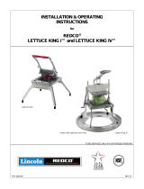
Lettuce King
®
I
400N, 401N, 402NC, 403N
Lettuce King
®
IV
4400N
Thank you for purchasing this Vollrath Food Processing Equipment. Before operating the equipment, read and familiarize yourself with
the following operating and safety instructions. SAVE THESE INSTRUCTIONS FOR FUTURE REFERENCE. Save the original box and
packaging. Use this packaging to ship the equipment if repairs are needed.

OperatOr’s Manual
2
ENGLISH
Safety PrecautionS
To ensure safe operation, read the following statements and understand
their meaning. This manual contains safety precautions which are
explained below. Please read carefully.
WARNING
Warning is used to indicate the presence of a hazard that can cause
severe personal injury, death, or substantial property damage if the
warning is ignored.
CAUTION
Caution is used to indicate the presence of a hazard that will or can
cause minor personal injury or property damage if the caution is
ignored.
NOTE
Note is used to notify people of installation, operation, or maintenance
information that is important but not hazard-related.
For Your Safety!
These precautions should be followed at all times. Failure to follow
these precautions could result in injury to yourself and others or
damage the equipment.
To reduce risk of injury or damage to the equipment:
Check equipment before each use to insure the equipment is clean.
Check for broken, nicked or dull blades and if found, replace the blade
assembly.
Check to insure that the pusher head sits down completely on the rubber
bumpers.
If necessary, lubricate guide rods using a light coating of mineral oil, Petro
Gel, or food grade lubricant. DO NOT USE COOKING OIL AS IT WILL
BECOME STICKY AND MAY PERMANENTLY DAMAGE THE PUSHER
HEAD BEARINGS
function and PurPoSe
Intended for cutting, dicing and wedging vegetables and fruits.
featureS and controlS
C
G
D
B
H
C
E
E
Figure 1. Features and Controls Lettuce King I.
A
A
J
H
E
E
F
G
J
J
D
K
C
C
I
I
B
Figure 2. Features and Controls Lettuce King IV.

3
ENGLISH
OperatOr’s Manual
A
GUIDE RODS. Guides and align the pusher head onto the blade
set.
B
HANDLE. Used to lower and raise the pusher head.
C
LEGS. Supports the equipment.
D
PUSHER HEAD ASSEMBLY. Made up of the guides and the
pusher head block (and the handle for tabletop models).
E
BUMPERS. Cushions the stop of the pusher head.
F
SAFETY LOCK HANDLE. Used to secure the pusher head block
in the up position.
G
BLADE ASSEMBLY. Houses the blades. Specically sized to
match the corresponding pusher head block.
H
BASE ASSEMBLY. Holds the guide rods and parts of the
equipment.
I
LEG SCREWS. Holds the legs in place.
J
LOCKING PIN. Secures the pusher head to the handle. Secures
the handle assembly to the base. Secures the safety lock to the
base.
K
SAFETY LOCK ARM. Used to secure the pusher head block in
the up position.
unPacking the equiPment and initial SetuP
Carefully remove crating or packaging materials from the equipment. Dispose
of all packaging ,materials in an environmentally responsible manner.
Leg installation Lettuce King I:
1. Use the screws (A) and washers (B) to install legs (C) tightening with
wrench (D). See Figure 3.
D
A
B
C
Figure 3. Legs, Hardware and Tool for the Lettuce King I.
2. Secure legs (C) to base (E) using screws (A) and washers (B). See
Figure 4.
B
A
B
A
E
E
C
Figure 4. Mounting the Legs on the Lettuce King I.
Leg installation Lettuce King IV:
1. Use the capscrews (A) and rubber washers (B) to install legs (C). See
Figure 5.
B
AB
A
E
E
C
Figure 5. Legs and Hardware for the Lettuce King IV.
2. Set legs (C) into the holes in the base assembly (D) so the angled part of
the leg faces outward. See Figure 5.
3. Secure legs (C) to base assembly (D) using capscrews (A) and rubber
washers (B). See Figure 5.
4. Tighten capscrews (A) slowly and rotate the legs slightly so that the end
of the capscrew (A) enters the notch (E) in the leg (C). See Figure 5.
C
D

OperatOr’s Manual
4
ENGLISH
4. Do not wipe across the blades or use scrub pads on this equipment.
Wiping across the sharp edge of the blade can cause injury and will dull
the blades.
5. The blade assembly (G) is best cleaned by forcing water under pressure
through the blades from the unsharpened side. If necessary, use a nylon
bristle cleaning brush to push food particles out from the unsharpened side
of the blade assembly (G).
6. Do not put this equipment in a dishwasher or dish machine with soaps,
detergents, or other alkaline chemicals that can harm the equipment.
7. After cleaning, let the equipment air dry.
8. Lubricate the sliding parts with mineral oil or Petro Gel after each use. Do
not use cooking oil as it will become sticky and may permanently damage
the equipment.
Preventative maintenance
1. Clean equipment after every use.
2. Use for intended purposes only.
3. Change blades regularly - based on usage.
rePlacing Blade aSSemBly
WARNING
Sharp Blade Hazard.
Blades are sharp and can cause cuts. To avoid
injury from sharp blades, handle with caution.
Wash new blades with warm, soapy water and rinse thoroughly to remove the
thin protective oil lm. Keep the sharp edge away from you when handling
blades.
Lettuce King I:
1. Familiarize yourself with the parts diagram for your equipment.
See Figure 6 (Spare Parts for Lettuce King I) for parts to reference for this
procedure.
2. Allow ample room to work on a at, dry surface.
3. Raise the handle and pusher head as far up as it will go.
4. Verify that the pusher head bumpers (R) are installed. If missing, clean the
surface and install new pusher head bumpers(s).
5. Remove the screws retaining the blade assembly (T). Carefully remove
and dispose the blade assembly.
6. Examine the pusher head (J) ngers. If they are nicked or burred, smooth
the rough edges with a small at le. The spaces between the ngers must
be uniform. Straighten any bent ngers.
7. Verify that blade shields (U) are installed on the blade assembly (T).
8. Place the blade assembly (T) into the base assembly (P) so the it is seated
correctly and the sharp side up.
9. Install the screws into the rear side of the blade assembly (T). Tighten until
contact is made with the base assembly (P). Turn the screw until tight, do
not exceed 1/2 turn or 40 in. lbs.
10. Place rubber washer between the base assembly (P) and the blade
assembly (T). Insert the screws through the frame, and rubber washer into
the blade assembly. Turn the screw until tight, do not exceed 1/2 turn or 40
in. lbs.
oPeration
WARNING
Sharp Blade Hazard.
Blades are sharp and can cause cuts. To avoid
injury from sharp blades, handle with caution.
Prior to rst use, it is important to clean the equipment. Wash new blades with
warm soapy water and rinse thoroughly to remove the thin protective oil lm.
1. Before each use, check that the equipment is clean and the blades are
in good condition. If loose or broken blades are found, blades must be
serviced.
2. Before each use, always check for proper blade alignment. Slowly set
the pusher head (D) onto the blade assembly. See Figures 1 and 2. They
should slide together with no obstructions. If there are obstructions, verify
they are a matching set.
3. Verify that the blade assembly and pusher head assembly are the desired
size.
4. Prepare the food product to be processed.
5. Lift the handle (B) and place the food on the blade assembly (G) with the
at side down. See Figures 1 and 2.
6. Lettuce King I: Remove hand from the blade assembly (G) area and place
that hand on the leg (C). See Figure 1.
Lettuce King IV: Hold the handle (B), remove hand from the blade
assembly area and place that hand on the lock lever (F). Push lock lever (F)
in to release the lock arm from the locked position. See Figure 2.
7. Using a strong, quick, downward thrust, force the food product through the
blade assembly.
8. Repeat this process until you have prepared enough food product for your
daily needs.
9. Clean and lubricate your equipment immediately after each use. See the
CLEANING section of this manual for more information.
cleaning
WARNING
Sharp Blade Hazard.
Blades are sharp and can cause cuts. To avoid
injury from sharp blades, handle with caution.
To maintain the appearance and increase the service life, clean your daily.
NOTE:
Food acids will make blades dull and corrode the metal.
Always clean this food preparation equipment immediately
after every use.
1. Raise the handle to put the highest position. See Figures 1 and 2.
2. Clean large excess pieces of scrap with the special brush provided with this
equipment.
3. Wipe, rinse or spray off equipment, pusher head and blade assembly
thoroughly with HOT water.

5
ENGLISH
OperatOr’s Manual
11. Slowly bring the pusher head (J) down to the blade assembly (T). If there
is contact, the pusher head may need to be adjusted. To adjust, loosen
the locking collar set screws (I) and position then adjust the pusher head
ngers. Tighten the locking collar set screws.
12. Lubricate the pusher head pivot rod with mineral oil or Petro Gel after
each use. Do not use cooking oil as it will become sticky and may
permanently damage the equipment.
Lettuce King IV:
1. Familiarize yourself with the parts diagram for your equipment.
See Figure 7 (Spare Parts for Lettuce King IV) for parts to reference for
this procedure.
2. Allow ample room to work on a at, dry surface.
3. Raise the handle and pusher head as far up as it will go.
4. Remove the screws retaining the blade assemblies (CC) and (DD).
Carefully remove and dispose the blade assemblies.
5. Examine the pusher head (K). If they are nicked or burred, smooth the
rough edges with a small at le.
6. Verify that blade shields (BB) are installed on the blade assembly (CC)
and (DD).
7. Place the lower blade assembly (CC) into the frame (H) so the it is
positioned correctly and the sharp side up.
trouBleShooting
If the equipment no longer processes food cleanly or without damage to the food product, the blades could be dull and be in need of replacement. Broken, bent,
or nicked blades must be replaced.
Problem It might be caused by Course of Action
Broken Blade. Blades were dull.
Pre-score whenever possible to avoid undue shock and stress to blades.
Replace the blade assembly.
8. Install the screws into the left side of the blade assembly (CC). Tighten
until contact is made with the frame (H). Turn the screw until tight, do not
exceed 1/2 turn or 40 in. lbs.
9. Place rubber washer between the right side frame (H) and the blade
assembly (CC). Insert the screws through the frame, and rubber washer
into the blade assembly. Turn the screw until tight, do not exceed 1/2 turn
or 40 in. lbs.
10. Place the upper blade assembly (DD) into the frame (H) so the it is
positioned correctly and the sharp side up.
11. Install the screws into the front side of the blade assembly (DD). Tighten
until contact is made with the frame (H). Turn the screw until tight, do not
exceed 1/2 turn or 40 in. lbs.
12. Place rubber washer between the back side frame (H) and the blade
assembly (DD). Insert the screws through the frame, and rubber washer
into the blade assembly. Turn the screw until tight, do not exceed 1/2 turn
or 40 in. lbs.
13. Slowly bring the pusher head down to the blades.
14. Lubricate the main frame guide rods with mineral oil or Petro Gel after
each use. Do not use cooking oil as it will become sticky and may
permanently damage the equipment.

OperatOr’s Manual
6
ENGLISH
LETTER PART NUMBER DESCRIPTION
A
060 RUBBER FOOT (OLD STYLE)
303 RUBBER FOOT, DEEP (NEW STYLE)
B 0655 RUBBER SEAL
C 414 SCREW FIL. HEAD., 1/4-20 X 3/4”
D 415 SCREW, HEX HEAD., 1/4-20 X 7/8”
E 420 BLADE BLOCK
F 424 BLADE BLOCK PIN
G 426 LEG CASTING, FRONT / REAR
H 427 BLADE BLOCK SCREW, 1/4-20 X 2”
I 4422R SET SCREW, SQ. HEAD., 1/4-20 X 3/8”
J
379062
PUSHER HEAD 3/16” - (Item 400N) INCLUDES:
4 (0.88 LONG) SPACERS, 74 (0.93 LONG) SPACERS, 38 FINGERS, 2 RETAINING RODS, 4 NUTS
483
PUSHER HEAD 1/4” - (Item 403N) INCLUDES:
56 SPACERS, 29 FINGERS, 2 RETAINING RODS, 4 NUTS
482
PUSHER HEAD 3/8” - (Item 402NC) INCLUDES:
38 SPACERS, 20 FINGERS, 2 RETAINING RODS, 4 NUTS
452
PUSHER HEAD 3/4” - (Item 401N) INCLUDES:
20 SPACERS, 11 FINGERS, 2 RETAINING RODS, 4 NUTS
K 453 PUSHER HEAD LOCKING COLLAR - INCLDS. COLLAR & SCREW
L 454 PUSHER HEAD PIVOT ROD
M 455 PUSHER HEAD HANDLE - INCLDS. HANDLE ROD & 2 PLASTIC GRIPS
N 456 PUSHER HEAD SIDE ARM - RIGHT HAND
O 457 PUSHER HEAD SIDE ARM - LEFT HAND
P 468 BASE ASSEMBLY (CASTING)
Q 490 NYLON WASHER
R 506 PUSHER HEAD BUMPER
S 519 ACORN NUT, 1/4”
T
435
BLADE ASSEMBLY 3/16” - (Item 400N) INCLUDES:
37 BLADES, 2 BLOCKS, 2 PINS, 2 SHIELDS
485
BLADE ASSEMBLY 1/4” - (Item 403N) INCLUDES:
28 BLADES, 2 BLOCKS, 2 PINS, 2 SHIELDS
484C
BLADE ASSEMBLY 3/8” - (Item 402NC) INCLUDES:
19 BLADES, 2 BLOCKS, 2 PINS, 2 SHIELDS
434
BLADE ASSEMBLY 3/4” - (Item 401N) INCLUDES:
10 BLADES, 2 BLOCKS, 2 PINS, 2 SHIELDS
U N/A BLADE SHIELD - PART OF BLADE ASSEMBLY
NOT SHOWN 4425 LETTUCE CUTTER BRUSH
SPare PartS liSt - lettuce king i

7
ENGLISH
OperatOr’s Manual
SPare PartS liSt - lettuce king i
A
B
C
D
E
F
G
H
M
N
O
P
I
J
K
L
Q
R
S
T
U
C
I
Figure 6. Spare Parts for Lettuce King I

OperatOr’s Manual
8
ENGLISH
SPare PartS liSt - lettuce king iv
LETTER PART NUMBER DESCRIPTION
A 0658
Rubber Seal
B 303
Rubber Foot
C 305
“O” ring
D 379017
Handle Bracket
E 379018
Leg (new style - do not intermix with old style)
F 379019
Screw, Stainless, Hex, 3/8-24 x 1”
G 379020
Spacer
H 850083
Guide Rod (also part of 4401)
I 4402
Blade Block (also part of blade assy 4408)
J 4403
Blade Pin (also part of blade assy 4408)
K 4404
Pusher Head
L 4405
Head Guide
M 4406
Screw, Hex, 1/4-20 x 4 1/2”
N 4407
Screw, Hex, 1/4-20 x 1 3/8”
O 4409
LEG (old style - do not intermix with new style)
P 4411
Pull Pin with ring, short, 1 1/4”
Q 4412R
Pull Pin with ring, long 1 3/4”
R 4413
Operating Arm Linkage
S 4414R
Operating Handle
T 4416
Safety Pivot Base
U 4417
Safety Latch Assembly
V 4424
Screw, Hex, 1/4-20 x 1/2”
W 4427
Screw, Phillips, 1/4-20 x 1 1/4”
X N/A
Plastic Cap (also part of 4417)
Y N/A
Aluminum Stop (also part of 4417)
Z N/A
Safety Latch (also part of 4417)
AA N/A
Screw, Hex, 1/4-20 x 1” (also part of 4417)
BB N/A
Blade Shield (part of blade assy 4408)
CC 4408
Blade Assembly (includes. 2 complete blade assy’s w/ shields)
DD N/A
Single Blade, 1/2” x 9-3/16” (packed 12 per carton) (part of blade assy 4408)
EE 4401
Main frame with guide rods
FF N/A
Head Guide Link (Not Shown) discontinued, refer to “D”)
NOT SHOWN 4425
Lettuce Cutter Brush
NOT SHOWN 2900
Drum Ring (Sold Separately)

9
ENGLISH
OperatOr’s Manual
SPare PartS liSt - lettuce king iv
A
B
D
E
F
G
H
I
J
K
L
M
N
O
P
Q
R
S
T
U
V
W
X
Y
Z
AA
N
N
V
N
B
BB
CC
DD
P
Figure 7. Spare Parts for Lettuce King IV.
C
EE

www.vollrath.com
The Vollrath Company, L.L.C.
1236 North 18th Street
Sheboygan, WI 53081-3201
U.S.A.
Main Tel: 800.628.0830
Fax: 800.752.5620
Technical Services: 800.628.0832
Service Fax: 920.459.5462
Canada Service: 800.695.8560
© 2014 The Vollrath Company, L.L.C.
Item No. 2350026-1 en Rev 07/14
Service and rePair
Please contact Vollrath Technical Service from the list below.
VOLLRATH Technical Service • 1-800-628-0832 (USA)
• Email: [email protected]
When contacting Vollrath Technical Service, please be ready with the item number, model number (if applicable), serial number, and proof of purchase showing the
date the equipment was purchased.
Warranty Statement for the vollrath co. l.l.c.
This warranty does not apply to products purchased for personal, family or household use, and The Vollrath Company LLC does not offer a written warranty to
purchasers for such uses.
The Vollrath Company LLC warrants each of its products listed below against defects in materials and workmanship for the applicable period provided below. All other
products manufactured or distributed by The Vollrath Company LLC are warranted against defects in materials and workmanship for a period of one year. In all cases,
the warranty runs from the date of the end user’s original purchase found on the receipt. Any damages from improper use, abuse, modication or damage resulting
from improper packaging during return shipment for warranty repair will not be covered under warranty.
Vollrath – Redco® products – The warranty period is 2 years.
Replacement parts – The warranty period is 90 days.
No remedy for normal use wear and tear or other causes not arising from defective material or workmanship. These components may be warranted if
manufactured defective or due to material defect.
For complete warranty information, product registration and new product announcement, visit www.vollrath.com.

Manual del operador
6
ESPAÑOL
lista de rePuestos - lettuce King i
LETRA
NÚMERO DE
PIEZA
DESCRIPCIÓN
A
060 PATA DE GOMA (ESTILO ANTIGUO)
303 PATA DE GOMA, PROFUNDA (ESTILO NUEVO)
B 0655 SELLO DE GOMA
C 414 TORNILLO 1/4-20 X 1.9 CM (3/4”)
D 415 TORNILLO, CABEZA HEX., 1/4-20 X 2.2 CM (7/8”)
E 420 BLOQUEADOR DE HOJAS
F 424 PASADOR, BLOQUEADOR DE HOJAS
G 426 PIEZA FUNDIDA PATAS, DELANTERA/POSTERIOR
H 427 TORNILLO BLOQUEADOR DE HOJAS, 1/4-20 X 5.1 CM (2”)
I 4422R TORNILLO CABEZA CUADR., 1/4-20 X 1 CM (3/8 PO”)
J
379062
CABEZAL DE EMPUJE 0.48 CM - INCLUYE: (0.88 CM) ESPACIADORES, (0.93 CM) ESPACIADORES, 38
DEDOS, 2 VARILLAS DE RETENCIÓN, 4 TUERCAS
452
CABEZAL DE EMPUJE 1.9 cm (3/4”) - INCLUYE:
20 ESPACIADORES, 11 DEDOS, 2 VARILLAS DE RETENCIÓN, 4 TUERCAS
482
CABEZAL DE EMPUJE 1 cm (3/8”) - INCLUYE:
38 ESPACIADORES, 20 DEDOS, 2 VARILLAS DE RETENCIÓN, 4 TUERCAS
483
CABEZAL DE EMPUJE 0.6 cm (1/4”) - INCLUYE:
56 ESPACIADORES, 29 DEDOS, 2 VARILLAS DE RETENCIÓN, 4 TUERCAS
K 453 COLLARÍN TRABANTE CABEZAL DE EMPUJE - INCL. COLLARÍN Y TORNILLO
L 454 VARILLA PIVOTANTE, CABEZAL DE EMPUJE
M 455 MANGO, CABEZAL DE EMPUJE - INCL. VARILLA DE MANGO Y 2 EMPUÑADURAS PLÁSTICAS
N 456 BRAZO LATERAL, CABEZAL DE EMPUJE - DERECHO
O 457 BRAZO LATERAL, CABEZAL DE EMPUJE - IZQUIERDO
P 468 PIEZA FUNDIDA BASE
Q 490 ARANDELA DE NYLON
R 506 TOPE, CABEZAL DE EMPUJE
S 519 TUERCA CIEGA, 1/4”
T
435
CONJUNTO DE HOJAS 0.48 CM - INCLUYE:
37 HOJAS, 2 BLOQUEADORES, 2 PASADORES, 2 PROTECCIONES
485
CONJUNTO DE HOJAS 0.6 cm (1/4”) - INCLUYE:
28 HOJAS, 2 BLOQUEADORES, 2 PASADORES, 2 PROTECCIONES
484C
CONJUNTO DE HOJAS 1 cm (3/8”) - INCLUYE:
19 HOJAS, 2 BLOQUEADORES, 2 PASADORES, 2 PROTECCIONES
434
CONJUNTO DE HOJAS 1.9 cm (3/4”) - INCLUYE:
10 HOJAS, 2 BLOQUEADORES, 2 PASADORES, 2 PROTECCIONES
U N/A PROTECCIÓN DE LA BASE - PARTE DEL CONJUNTO DE HOJAS
NO SE MUESTRA 4425 CEPILLO, CORTADOR DE LECHUGAS

7
Manual del operador
ESPAÑOL
lista de rePuestos - lettuce King i
A
B
C
D
E
F
G
H
M
N
O
P
I
J
K
L
Q
R
S
T
U
C
I

9
Manual del operador
ESPAÑOL
lista de rePuestos - lettuce King iv
A
B
C
D
E
F
G
I
J
K
L
M
N
O
P
Q
R
S
T
U
V
W
X
Y
Z
AA
N
N
V
N
B
BB
CC
DD
P
H
EE

OperatOr’s Manual
6
FRANÇAIS
liste des piÈCes détaCHées - lettuCe King i
LÉGENDE NUMÉRO DE PIÈCE DESCRIPTION
A
060 PIED EN CAOUTCHOUC (STYLE ANCIEN)
303 PIED EN CAOUTCHOUC, PROFOND (NOUVEAU STYLE)
B 0655 JOINT EN CAOUTCHOUC
C 414 VIS, CRUCIFORME, 1/4-20 X 1.9 CM (3/4 PO)
D 415 VIS, TÊTE À SIX PANS, 1/4-20 X 2.2 CM (7/8 PO)
E 420 BLOC DE LAMES
F 424 GOUPILLE DU BLOC DE LAMES
G 426 PIED, AVANT/ARRIÈRE
H 427 VIS DE BLOC DE LAMES, 1/4-20 X 5.1 CM (2 PO)
I 4422R VIS, TÊTE CARRÉE, 1/4-20 X 3/8 PO
J
379062
TÊTE DE POUSSÉE 0.48 CM (3/16 PO) - COMPREND :
(0.88 CM) ESPACEURS, (0.93 CM) ESPACEURS, 38 DOIGTS, 2 TIGES DE RETENUE, 4 ÉCROUS
452
TÊTE DE POUSSÉE 1.9 CM (3/4 PO) - COMPREND :
20 ESPACEURS, 11 DOIGTS, 2 TIGES DE RETENUE, 4 ÉCROUS
482
TÊTE DE POUSSÉE 1 CM (3/8 PO) - COMPREND :
38 ESPACEURS, 20 DOIGTS, 2 TIGES DE RETENUE, 4 ÉCROUS
483
TÊTE DE POUSSÉE 0.6 CM (1/4 PO) - COMPREND :
56 ESPACEURS, 29 DOIGTS, 2 TIGES DE RETENUE, 4 ÉCROUS
K 453 COLLIER DE SERRAGE DE TÊTE DE POUSSÉE - COMPREND COLLIER ET VIS
L 454 TIGE DE PIVOT DE TÊTE DE POUSSÉE
M 455 POIGNÉE DE TÊTE DE POUSSÉE - COMPREND TIGE DE POIGNÉE ET 2 PRISES EN PLASTIQUE
N 456 BRAS LATÉRAL DE LA TÊTE DE POUSSÉE - MAIN DROITE
O 457 BRAS LATÉRAL DE LA TÊTE DE POUSSÉE - MAIN GAUCHE
P 468 SOCLE
Q 490 RONDELLE EN NYLON
R 506 CAOUTCHOUC DE TÊTE DE POUSSÉE
S 519 ÉCROU BORGNE, 1/4 PO
T
435
JEU DE LAMES 0.48 CM - COMPREND :
37 LAMES, 2 BLOCS, 2 GOUPILLES, 2 PROTECTIONS
485
JEU DE LAMES 0.6 CM (1/4 PO) - COMPREND :
28 LAMES, 2 BLOCS, 2 GOUPILLES, 2 PROTECTIONS
484C
JEU DE LAMES 1 CM (3/8 PO) - COMPREND :
19 LAMES, 2 BLOCS, 2 GOUPILLES, 2 PROTECTIONS
434
JEU DE LAMES 1.9 CM (3/4 PO) - COMPREND :
10 LAMES, 2 BLOCS, 2 GOUPILLES, 2 PROTECTIONS
U N/A PROTECTION DE LAME - FAIT PARTIE DU JEU DE LAMES
SANS OBJET 4425 BROSSE POUR COUPE-LAITUE
/
