Page is loading ...

Texmate, Inc. Tel. (760) 598-9899 • www.texmate.comDL-40JANUS-DCA/DCV manual (d0114) Page 1
• Externaltransmittersorsignalconditionerscanbeeliminat-
edbydirectconnectionofthesensoroutputto:
– DCA
ID02 : DC mV ±20mV, ±50mV, ±100mV, ±200mV w/24V Exc.
– DCV
ID01 :
DC-Volts 2V/20V/200V w/24V Exc.
ID05 : DC-Volts 2V/20V/200V w/24V Exc. and Zero offset
adjustable pot
• Optionalisolated14bitanalogoutput.Userorfactoryscalable
to4to20mA,0to20mAor0to10Vacrossanydesired
digitalspanfrom±onecounttothefullscalerangeof–1999
to9999(12000counts).
• OptionalIsolatedModbusRTURS-485serialcommunication
withselectablebaudrate(9600,19200),addressandparity.
• Auto-sensingAC/DCpowersupply.Forvoltagesbetween
85-265 VAC / 95-300 VDC (PS1) or15-48VAC/10-72VDC(PS2).
• Standardredoroptionalgreenorsuperbrightred4-digitLED
withdisplayrange–1999to9999(12000counts).
• Redorgreen0.8”LEDlargedisplayoption
• FourannunciatorLEDsprovidefrontpanelalarmstatus
indicationforuptofoursetpoints.
• Uptooptionalsixrelaysincombinationofsix,fourortwo4
AmpFormArelaysortwo9AmpFormCwithtwoorfour4
AmpFormArelaysareavailable.
• Automaticintelligentaveragingsmoothsnoisysignals,while
providingafastdisplayresponsetorealinputsignalchanges.
• Three-buttonprogrammingfromthefrontpanel
(UP,DOWNandPROGRAMbuttons).
AutoCalibrationMode ............5
AutoCalibrationProcedure........5
CaseDimensions ...............13
ConnectorPinouts........... 10-11
ControlsandIndicators...........2
ComponentLayout..............12
DigitalSpanSelectionforAnalog
RangeOutput...................6
DecimalPoint&BrightnessSelection
..6
GeneralFeatures................1
GlossaryofProgrammingSymbols ..2
InputModuleComponentGlossary
. .13
InstallationGuideline............11
LensCover&MetalSurroundCase 14
ManualRescaling................4
ManualRescalingProcedure.......4
MeterAssembly ................10
ModbusRTU&RS-485Settings....7
ModbusRTUImplementation......7
ModbusAddressforDL-40Registers8
OrderingInformation............15
Setpoint&RelayConfigurationMode....9
SoftwareFeatures...............1
SoftwareLogicTree ..............3
Specifications...................1
TwoPointAnalogOutputRange
SettingandCalibration............6
General Features Specifications
Software Features
Index
LEOPARD FAM ILY
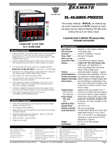
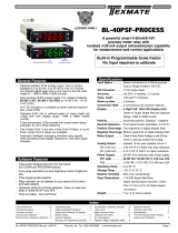
DL-40JANUS-DCA
20/50/100/200mV DC Full Scale
DL-40JANUS-DCV
2/20/200V DC Meter
Two scaling methods - MANUAL (no external sig-
nal source required) and AUTO (requied an exter-
nal signal source). Optional Modbus RS-485 serial,
analog and up to six relays output.
• Frontpanelselectablefour-levelbrightnesscontrolfordigital
displayandsetpointLEDs.
• Fourprogrammablesetpoints.
• Relayactivationcanbeselectedtooccurabove(HI)orbelow
(LO)eachsetpoint.
• Hysteresissettingforallfoursetpoints.Delayonmakeand
delayonbreakforSP1andSP2.
• PeakandValley.ViewandReset.
• ProgramLockswitch
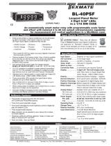
4 Digit 0.56” or 0.8” LEDs
in a 1/8 DIN CASE
Input Specs: ..............Depends on Input signal conditioner
A/D Converter: ..........14 bit single slope
Accuracy: ..................±(0.05% of reading + 2 counts)
Temp. Coeff.: .............100 ppm/°C (Typical)
Warm up time: ...........2 minutes
Conversion Rate: ......5 conversions per second (Typical)
Display: ......................4 digit 0.56" Red LED display (std),
0.56” Green, 0.8" Red/Green, or
0.56" Super Bright Red are optional.
Range
0 to 9999 counts.
Polarity: .....................Assumed positive. Displays – negative
Decimal Selection: ....Front panel button selectable, X•X•X•X•
Positive Overrange: ..Top segments of digital display flash
Negative Overrange: .Bottom segments of digital display flash
Relay Output: ............Up to Six Relays in combination of six,
four or two 4 Amp Form A relays or two
9 Amp Form C with two or four 4 Amp
Form A relays.
Analog Output: .........Isolated 16 bit user scalable mA or V
AIC (mA out) ...........
4-20 mA @ 0 to 500Ω max loop resistance
AIV (volts out) .......... 0-10 V DC @ 500 Ω or higher resistance
Power Supply: ...........AC/DC Auto sensing wide range supply
PS1 (std) ................
85-265 VAC / 95-300 VDC, 50-400Hz @ 3W
PS2 .........................
15-48 VAC / 10-72 VDC, 50-400Hz @ 2.5W
Operating Temp.: ......0 to 50 °C
Storage Temp: ...........–20 °C to 70 °C.
Relative Humidity: ....95% (non condensing)
Case Dimensions: ....1/8 DIN, Bezel: 96x48 mm (3.78”x1.89”)
Depth behind bezel: 117 mm (4.61”)
Plus 11.8 mm (0.47”) for Right-angled
connectors, or plus 20 mm (0.79”) for
Straight-thru connector.
Weight: .......................6.5 oz., 8.5 oz when packed
Certification ...............UL Listed.
DC Amp or DC Volt Meter, Transmitter and Controller

Texmate, Inc. Tel. (760) 598-9899 • www.texmate.comPage 2 DL-40JANUS-DCA/DCV manual (d0114)
Symbol Explanation
This symbol represents the
OPERATIONAL DISPLAY.
This is the PROGRAM button.
This is the UP button.
This is the DOWN button.
When a button is shown, press and
release it to go onto the next step in the
direction indicated by the arrow. When two
or more buttons are shown, each with an
arrow, this indicates that there is a number
of programming choices.
When two buttons are shown side by side
and enclosed by a dotted line, they must
be pressed at the same time then released
to go onto the next programming step.
If the display is shown with XXXX it means
the value displayed will be the previously set
value. When a number is shown it indicates
the initial factory default setting or a specific
“example number”.
P
P
When two displays are shown together with
bursts, this indicates that the display is
toggling (flashing) between the name of the
function and the value.
Text or numbers shown between square
brackets in a procedure indicate the pro-
gramming code name of the function or the
value displayed on the meter display.
When the
and
buttons are shown
together, the display value can be increased
by pressing and releasing the
button
or decreased by pressing and releasing the
button.
When the
and
buttons are shown
with two displays, either display can be
selected by pressing and releasing the
or
buttons.
When there are more than two display selec-
tions they are shown in brackets below the
first display and are also selectable by press-
ing and releasing the
or
buttons.
A dotted box indicates these functions are
omitted or bypassed when the related hard-
ware is not present
To explain software programming procedures, logic diagrams are
used to visually assist in following the programming steps. The
fol-lowing symbols are used to represent various functions and
associated display elements of the meter:
DOWN ARROW
BUTTON
Setpoint
Annunciator
LEDs
SP4
SP3
SP2
SP1
PROGRAM
BUTTON P
Setpoint Annunciator LEDs
SP1 SP2 SP3 SP4
[LHLH]
[HLHL]
[LLLL]
Front Panel Buttons
Program Button
The
P
button is used to move from one program step to the next.
When pressed at the same time as the button, it initiates the
calibration mode. When pressed at the same time as the but-
ton, it initiates the setpoint setting mode.
Up Button
When in the operational display, pressing the button alone,
allows you to view and reset the Peak and Valley (Highest and
Lowest Readings.)
When in the calibration mode or the setpoint setting mode the
button is used to increase the value of the displayed parameter.
Down Button
When in the operational display, pressing the button alone,
allows you to view, but not change, the setting of setpoint 1,2,3
& 4.
When in the calibration mode or the setpoint setting mode the
button is used to decrease the value of the displayed parameter.
Glossary of Programming Symbols
Controls and Indicators
[ScAL]
[9999]
UP ARROW
BUTTON

Texmate, Inc. Tel. (760) 598-9899 • www.texmate.comDL-40JANUS-DCA/DCV manual (d0114) Page 3
The DL-40JANUS is an intelligent meter with a hierarchical
software structure designed for easy programming and opera-
tion, as shown below in the software logic tree.
After the meter has been powered up, the four
digits light up for three seconds and then settle to
the operational display indicating the input signal.
15 Second
Program Timeout
The meter has a 15 second
program timeout. If no buttons
are pressed for 15 seconds, at
any stage of the programming
sequence the meter will exit the
programming mode and return
to the operational display. Any
program changes that were
made prior to pressing the
P
button in the preceding step
will not be saved.
Software Logic Tree
SETPOINT SETTING AND
RELAY CONFIGURATION MODE
See Page 9
Set Setpoint 1
(SP1)
Delay-on-Make
(doM)
Delay-on-Break
(dob)
Setpoint 2
(SP2)
Hysteresis
(HYSt)
Hysteresis
(HYSt)
Hysteresis
(HYSt)
Hysteresis
(HYSt)
Delay-on-Make
(doM)
Delay-on-Break
(dob)
Setpoint 3
(SP3)
NOTE: [dob] [dom] Functions
are only available
for SP1 and SP2
Setpoint 4
(SP4)
Relays Activation [rLYS]
(H) High the relay energizes
when the setpoint is exceeded.
(L) Low the relay energizes below
the setpoint. Setpoint are indicated
from left to right SP1, SP2, SP3, SP4
Peak
Reset
PEAK
Reset
VALY
Setpoint 1
(SP1)
confirm (SP1) confirm
Peak
confirm
Valley
confirm Analog
output values
confirm (SP2)
confirm (SP3)
Setpoint 2
(SP2)
[LHLH]
[HLHL]
[HHHH]
MAIN MENU
Operational Display
SETPOINT
VIEW ONLY MODE
PEAK & VALLEY
VIEW & RESET
Sub-menu
MODE
Calibration
Mode
Calibration
Mode
DECIMAL POINT AND
BRIGHTNESS SELECTION
See Page 6
Setpoint 3
(SP3)
Setpoint 4
(SP4)
Valley
Offset
Scale
Factor
Calibrate
Analog
Output
Lo
Calibrate
Analog
Output
Hi
[X•XXX]
[XX•XX]
[XXX•X]
[XXXX•]
[XXXX]
[2]
[3]
[4]
Decimal Point
(dp)
Display
Brightness (br)
TWO POINT ANALOG OUTPUT
CALIBRATION
SEE PAGE 6
MANUAL
RESCALING MODE
See Page 4
SELECTION FOR ANALOG
RANGE OUTPUT
See Page 6
confirm (SP4)
confirm
confirm
confirm
This menu only available
when an analog output
module is installed
When MANUAL
is set to ON
When AUTO
is set to OFF
Span
Zero
Err. Any new setting
canceled and previous
settings are retained
TWO POINT AUTO
CALIBRATION MODE
SEE PAGE 5
This menu only available
when an analog output
module is installed
Modbus RS-485 Settings
See Page 7-8
BAUD: -press Up button for 192(00)
-press Down button for 96(00)
ADDR: -press Up or Down button to change
from 1 to 247.
-value rolls over, e.g. 247 to 1
PRTY: -press Up or Down button to change
-values are 2=Even, 1=Odd, 0=None
Texmate’s Modbus RTU RS-485 module provides
half-duplex, serial communication to PLC, SCADA and
other systems for monitoring and control of the meter’s
functions. The meter functions as a slave.
The RS485 module takes the place of the Analog Output
module, so it is not possible to have both Analog
Output and RS-485 communication. Programming and
operation of the meter are done via a dierent menu
system, or Software Logic Tree, that is accessed through
the front panel push buttons, see below.
14 158 9 10 11
See Leopard Family Input
Signal Conditioning Modules
1 2 3 4 5 6
Relay Outputs
AC
Neutral
– DC
AC
Line
+ DC
(Lock) ON COM Ref A+
29 28 27 26 25 24 23 22
B
12
With RS-485 Output Option
MANUAL rescaling- (without external signal) ON
AUTO scaling- (with external signal) OFF
17 1619 18
ON
SP1
NO
SP1
NO
SP2
NO
SP2
NO

Texmate, Inc. Tel. (760) 598-9899 • www.texmate.comPage 4 DL-40JANUS-DCA/DCV manual (d0114)
When the rear Auto/Manual switch is in the Manual position, the meter can be rescaled without applying an external signal by
changing the oFSt (offset) and SCAL (scale) parameters in the user menu. A pre-calibrated Input Signal Conditioning module must
be used. The meter assumes that this calibration used a true zero input (0V from conditioner to meter) resulting in a display value
of 0 and a maximum input signal span (2V from conditioner to meter) resulting in a display value of the SCAL value set in the user
menu. The linear equation is y = mx + b where m = (SCAL-0)/(2-0) and b = oFSt.
The default value of SCAL is 2000, but it may be set to any value between -1999 and +9999.
The internal Signal Span is limited to 3 V DC between- 1 V DC to+ 2 V DC. Any outputs from an Input Signal Conditioning module
that exceed these limits will cause the meter to indicate overrange regardless of the Digital Display Span scaled. For example,
an ID01 DC Volts Input Signal Conditioner can read +/-2VDC, but in the DL-40 will show under-range for a -1.2V input.
STEP A Enter the Calibration Mode
1) Press the
P
and buttons at the same time.
Display toggles between [CAL] and [oFF].
2) Press and hold the or button.
Display changes from [oFF] to [on].
3) Press the
P
button. Display toggles between [CAL] and [out].
STEP B Select Between Calibration of Input or Output
Note: If the analog output option is not present, Step B is skipped and the
program goes directly from Step A to Step C.
1) Press the or button to select the display toggling from [CAL]
to [inPt].
2) Press the
P
button. Display toggles between [oFSt] and the
previous offset setting.
STEP C Set the Offset on the Digital Display
1) Using the and buttons, adjust the digital display to the
desired offset. This is the reading that the meter will display for a
zero input.
2) Press the
P
button. Display toggles between [SCAL] and the
previous Scale factor.
STEP D Set the Scale factor on the Digital Display
1) Using the and buttons, adjust the meter display to the
desired Scale factor. The default value is 2000, for which a 2V
input will read 2000. If the scale factor is changed the display will
change proportionately. Therefore if the Scale factor is changed
to 1000 then for the same 2V input the display would read 1000.
2) Press the
P
button.
The Digital Calibration Procedure Mode is Now Complete.
The menu branches to the DECIMAL POINT AND BRIGHTNESS SE
LECTION,
(see page6) and the display flashes [dP] and the previous
decimal point selection.
Manual Rescaling Mode
Manual Rescaling Procedure
MAIN MENU
Operational Display
Sub-menu
MODE
STEP A Calibration
Mode
STEP B Calibration
Mode
DECIMAL POINT AND
BRIGHTNESS SELECTION
See Page 6
STEP C Offset
STEP D Scale
Factor
DECIMAL POINT AND
BRIGHTNESS SELECTION
See Page 6
Decimal Point
(dp)
TWO POINT ANALOG
OUTPUT RANGE SETTING
AND CALIBRATION
SEE PAGE 6

Texmate, Inc. Tel. (760) 598-9899 • www.texmate.comDL-40JANUS-DCA/DCV manual (d0114) Page 5
When the rear Auto/Manual switch is in the Auto position, the meter can be calibrated with an automatic scale factor calculation,
by applying a low input signal (InLo), entering the desired low display reading for that signal (ZERO), then applying a high input
signal (InHi), and then entering the desired high display reading (SPAN). The meter then automatically calculates and programs in
the requisite scale factor using a true linear (y=mx + b) calculation where m = (SPAN-ZERO)/(InHi-InLo) and b = ZERO, but within
the following parameters.
1. Positive and negative signals may be applied, but the difference between the high and the low signal inputs must be at least 1000
counts or Err will be indicated.
2. Positive and Negative values for the desired reading can be entered, but the scale factor created can not exceed the Digital
Display Span capability of the meter which is 12,000 counts between –1999 to 9999.
3. The internal Signal Span is limited to 3 V DC between – 1 V DC to + 2 V DC. Any outputs from an Input Signal Conditioning
module that exceed these limits will cause the meter to indicate overrange regardless of the Digital Display Span scaled.
Note: Most input signal conditioners have provisions for analog calibration and scaling. If the meter’s digital scale factor is set to
read zero with a zero input (shorted input), and to read 1000 with a 1.000 V input, any pre-calibrated signal conditioner with an
output that does not exceed – 1 V to + 2 V, will read correctly in the meter without any further calibration.
STEP A Enter the Calibration Mode
1) Press the
P
and buttons at the same time.
Display toggles between [CAL] and [oFF].
2) Press and hold the or button.
Display changes from [oFF] to [on].
3) Press the
P
button. Display toggles between [ZErO] and the
previous zero setting.
STEP B Select Between Two Point Digital Calibration of Input Signal and
Two Point Analog Output
Note: If the analog output option is not present, Step B is skipped and the
program goes directly from Step A to Step C.
1) Press the or button to select the display toggling from [CAL]
to [inPt] input calibration.
2) Press the
P
button. Display toggles between [ZErO] and the
previous zero setting.
STEP C Set the Meter’s Low Input Signal Reading on the Digital Display
1) Apply a zero or low signal to the meter.
(Positive or negative values are allowed)
2) Using the and buttons, adjust the meter display to the
desired reading for the applied low input signal.
3) Press the
P
button. Display toggles between [SPAn] and the
previous span setting.
STEP D Set the Meter’s High Input Signal Reading on the Digital Display
1) Apply a high input signal to the meter.
2) Using the and buttons, adjust the digital display to the
desired reading for the applied high input signal.
3) Press the
P
button.
The Digital Calibration Procedure Mode is Now Complete.
If the digital calibration was successfully completed, the menu
branches to the DISPLAY FUNCTION CONFIGURATION MODE,
(see page 7) and the display flashes [dP] and the previous setting.
ERROR Indicates Unsuccessful Calibration
If the calibration was unsuccessful, the display indicates [Err],
the new calibration settings just entered will not take effect and
the previously stored setting will remain.
The three most likely causes of an error during calibration are:
1) The full scale and zero signals were too similar. The full scale
signal must be at least 1000 counts greater than the zero or
low input signal (positive and negative values are allowed).
2) The scaling requirement exceeded the capability of the meter
(–1999 to 9999).
3) No input signal present, or incorrect connections.
Auto Calibration Mode
Auto Calibration Procedure
MAIN MENU
Operational Display
Sub-menu
MODE
STEP A Calibration
Mode
STEP B Calibration
Mode
DECIMAL POINT AND
BRIGHTNESS SELECTION
See Page 6
STEP C Zero
STEP D Span
DECIMAL POINT AND
BRIGHTNESS SELECTION
See Page 6
Decimal Point
(dp)
Err. Any new setting
canceled and previous
settings are retained
TWO POINT ANALOG
OUTPUT CALIBRATION
SEE PAGE 6

Texmate, Inc. Tel. (760) 598-9899 • www.texmate.comPage 6 DL-40JANUS-DCA/DCV manual (d0114)
STEP A Enter the Calibration Mode
1) Press the
P
and buttons at the same time.
Display toggles between [CAL] and [oFF].
2) Press the or button. Display changes from [oFF] to [on].
3)
Press the
P
button. Display toggles between [CAL] and [out] input calibration.
Note: If at this point the display skips directly to toggle between [oFSt] (Manual) or [ZErO]
(Auto) and the previous setting, the software is detecting that the optional analog output hard-
ware is NOT installed.
STEP B Enter the Analog [oUT] Output Mode
1)
Press the
P
button. Display toggles between [CLo] and an internal scale factor.
STEP C Set or Calibrate the [CLo] Low Analog Output Range
1) Select the voltage or current loop output header position on the output
module. (See Component Layout on page 9).
2) Connect a multimeter to pins 16 and 17 on the output module. (See Rear
Panel Pinouts on page 8). Using the and buttons, adjust the analog
output to the desired low value as shown on the multimeter display.
cLo may be adjusted to any value from –0.3 mA to 17 mA (mA output
selected) or from –0.6 V to 8 V (volt output selected)
3)
Press the
P
button. Display toggles between [CHi] and an internal scale factor.
STEP D Set or Calibrate the [CHi] High Analog Output Range
1) Using the and buttons, adjust the analog output to the desired high
value as shown on the multimeter display. CHi may be adjusted to any value
from 17 mA to 21 mA (mA output selected) or from 8 V to 10.3 V (volt out
put selected)
2) Press the
P
button. The display exits the calibration mode and returns to
the operational display.
Note: Having established the Low and High range of the analog output, the digital span
can now be selected which will set the two digital points between which the analog out-
put will occur. (See Digital Span Selection below).
STEP A Enter the Decimal Point and Brightness Mode Through the Sub Menu
[CAL] [oFF]
1) Press the
P
and buttons at the same time.
Display toggles between [CAL] and [oFF].
2) Press the
P
button. Display shows previous [dP] selection.
STEP E Set the Decimal Point
1) Using the and , adjust the display to the desired decimal point setting.
2)
Press the
P
button. Display toggles between [br] and the previous [br] setting.
STEP F Set the Display Brightness
1) Using the and buttons, adjust the display to the desired brightness
setting (4 is the brightest setting).
2) Press the
P
button. Display brightness changes to new setting
and display
toggles between [AnHi] and the previous [AnHi] setting.
STEP G Setting the Digital Span Point for Analog High Output
1) Using the and buttons, adjust the display to the desired digital value
which sets the point at which the selected analog high output range will occur.
2)
Press the
P
button. Display toggles between [AnLo] and previous [AnLo] setting.
STEP H Setting the Digital Span Point for Analog Low Output
1) Using the and buttons, adjust the display to the desired digital value
which sets the point at which the selected analog low output range will occur.
2) Press the
P
button.
The display exits the calibration mode and returns to
the operational display.
Note: Any two digital scale points from –1999 to 9999 can be selected. The digital scale
points for analog high and analog low can be reversed for reversed 20-4 mA output. The
span of the digital scale can be as small as two counts however small spans cause the 16
bit D to A to increment in stair case steps.
Two Point Analog Output Range Setting and Calibration
Decimal Point and Brightness Selection
Digital Span Selection for Analog Range Output
MAIN MENU
Operational Display
Sub-menu
MODE
STEP A Calibration Mode
TWO POINT AUTO
CALIBRATION or
MANUAL RESCALING MODE
See page 4 and 5
STEP B Calibration Mode
STEP C Calibrate Analog
Output Lo
STEP D Calibrate Analog
Output Hi
DECIMAL POINT AND
BRIGHTNESS SELECTION
[X•XXX]
[XX•XX]
[XXX•X]
[XXXX•]
[XXXX]
[2]
[3]
[4]
STEP E Decimal
Point (dp)
STEP F Display
Brightness (br)
STEP G Analog
High (Anhi)
STEP H Analog
Low (AnLo)
Confirm
DIGITAL SCALE AND SPAN
SELECTION FOR FULL SCALE
ANALOG RANGE OUTPUT

Texmate, Inc. Tel. (760) 598-9899 • www.texmate.comDL-40JANUS-DCA/DCV manual (d0114) Page 7
The Modbus/RS-485 communication settings sub-menu allows
you to set the following parameters:
a) Baud Rate – this is the baud rate of the RS-485 serial communi-
cation between the meter (slave) and Modbus master. Options are
9600 (default, meter shows “96”) and 19200 (meter shows “192”).
b) Address – this is the meter’s Modbus address on the RS-485
loop. Typically, RS-485 limits the number of devices on the loop to
32, but the DL-40 supports the full Modbus address range of 1-247.
Address 1 is the default value.
c) Parity – this is the parity setting for the RS-485 serial commu-
nication between the meter (slave) and Modbus master. Options
are: None (display shows “0”; Odd (display shows “1”); Even
(default, display shows “2”).
The meter’s response time to a read command from the master is
40-45msec (typically 42msec). The response time for a write com-
mand is 70-75msec (typically 72msec). This is due to the module
having to communicate to the meter’s core firmware to complete
the desired command. Exception responses are handled directly
by the module and typically have a response time of 3msec.
Modbus RTU & RS-485 Communication Settings
The DL-40 Modbus communication module supports the following
Modbus commands:
a) Read Holding Register (0x03)
b) Write Single Register (0x06)
Modbus addresses for DL-40JANUS registers are shown on
the next page
The following are some things to note about particular registers:
a) Modicon address 40001 RELAY has the bit values for Sp3 &
Sp4 and LED3 & LED4 reversed. There is an historical reason
for this, and we have chosen to maintain backward compatibili-
ty in case customer’s want to send their meters in for a Modbus
upgrade (at a nominal fee).
b) Modicon addresses 40002 INP, 40026 PEAK, 40027 VALY,
40029 ZERO, 40029 SPAN return a 2 byte hexadecimal value
of the meter’s display (in counts) and does not include the deci-
mal point. If you need the decimal value with decimal point, you
will need to read the register, convert it to decimal, read 40024
(see below) to determine decimal location, then combine the
two. Display counts are in Two’s Complement notation.
a. Hex values for 0 to 9999 are 0x0000 to 0x270F.
b. Hex values for -1 to -1999 are 0xFFFF to 0xF831.
c. Over-range is indicated by a returned value of 9999
(0x270F).
d. Under-range is indicated by a returned value of -1999
(0xF831).
c) In order for Sp3 and Sp4 set point settings to work, the DL-40
must have the optional Output Carrier Board installed (P/N
SA-DL/OM-CB).
d) All Delay on Make (DoM), Delay on Break (DoB) and Hysteresis
values are in units of whole seconds.
e) Modicon address 40023 RLYMOD uses the following values
to set the relay activation mode (letter sequence is SP1, SP2,
SP3, SP4):
a. 0 for HHHH
b. 1 for HLHL
c. 2 for LHLH
d. 3 for LLLL
e. H means relay is energized if input is equal to or
exceeds setpoint; L means relay is energized if input
is less than setpoint.
f. Note that the meter will not show the last two letters if
the Output Carrier Board option is not installed.
f) Modicon address 40023 DP uses the following values to set the
display decimal point location:
a. 0 for XXXX (none)
b. 1 for XXXX.
c. 2 for XXX.X
d. 3 for XX.XX
e. 4 for X.XXX
g) Modicon address 40025 BRIGHT must be a value between 1
(most dim) to 4 (most bright).
h) Modicon addresses 40028 and 40029 will have different mean-
ings depending on the Auto calibration or Manual rescaling
operational selection (see Auto Calibration Mode or Manual
Rescaling Mode above). These are explained in the register
table below.
i) Modicon addresses 40030 IZERO and 40031 ISPAN return
hexadecimal values related to the Auto Mode calibration of the
meter. They do not necessarily match expected values due vari-
ations and tolerances in the measurement circuit components,
e.g., calibrating with a value of zero volts for the ZERO value
may return a value of 0xFFFE (-2). These registers have no
meaning in Manual Rescaling Mode).
Modbus RTU Implementation

Texmate, Inc. Tel. (760) 598-9899 • www.texmate.comPage 8 DL-40JANUS-DCA/DCV manual (d0114)
Modbus Addresses for DL-40 Registers
MODICON
ADDRESS
MODICON
ADDRESS
TYPE R/W MIN. MAX. Register DESCRIPTION
40001 0x0000 UINT16 R - - RELAY B_0 SP1 Status
B_1 SP2 Status
B_3 SP4 Status
B_2 SP3 Status
B_4 LED1 Status
B_5 LED2 Status
B_7 LED4 Status
B_6 LED3 Status
40002 0x0001 SIN T16 R-1999 9999 INP Hexadecimal value of displayed
value
40003 0x0002 UINT16 R96/192 -BAUD Modbus baud rate stored as 96
for 9600 or 192 for 19200, set
by user via menu interface.
40004 0x0003 UINT16 R 1 247 ADDR Modbus meter address stored as
a value between 1 - 247, set by
user via menu interface.
40005 0x0004 UINT16 R 0 2 PARITY Modbus parity value stored as
a value of 0 (no parity), 1 (odd
parity) or 2 (even parity), set by
user via menu interface.
40 011 0x000A SINT16 R/W -1999 9999 PRES1 Setpoint 1 setting
40012 0x000B UINT16 R/W 09999 P1DOM Setpoint 1 DoM setting
40013 0x000C UINT16 R/W 09999 P1DOB Setpoint 1 DoB setting
40 014 0x000D UINT16 R/W 09999 HYST1 Setpoint 1 Hysteresis setting
40015 0x000E SI NT16 R/W -1999 9999 PRES2 Setpoint 2 setting
40016 0x000F UINT16 R/W 09999 P2DOM Setpoint 2 DoM setting
40 017 0x0010 UINT16 R/W 09999 P2DOB Setpoint 2 DoB setting
40018 0x0011 UINT16 R/W 09999 HYST2 Setpoint 2 Hysteresis setting
40019 0x0012 SINT16 R/W -1999 9999 PRES3 Setpoint 3 setting
40020 0x0013 UINT16 R/W 09999 HYST3 Setpoint 3 Hysteresis setting
40021 0x0014 SINT16 R/W -1999 9999 PRES4 Setpoint 4 setting
40022 0x0015 UINT16 R/W 09999 HYST4 Setpoint 4 Hysteresis setting
40023 0x0 016 UINT16 R/W 0 3 R LYMO D Relay activation polarity (H, L,
disabled, e.g., HHHH)
40024 0x0017 UINT16 R/W 0 4 DP Decimal Point setting
40025 0x0018 UINT16 R/W 1 4 BRIGHT Brightness setting
40026 0x0019 UINT16 R/W - - PEAK Peak (maximum) measured
value, writing any value resets
this register
40027 0x001A UINT16 R/W - - VA LY Valley (minimum) measured
value, writing any value resets
this register
40028 0x001B SINT16 R-1999 9999 ZERO
(Auto Mode
Only)
Displayed value for the min-
imum input signal value that
is applied during Auto Mode
calibration
40029 0x001C SINT16 R-1999 9999 SPAN
(Auto Mode
Only)
Displayed value for the max-
imum input signal value that
is applied during Auto Mode
calibration
40028 0x001B SINT16 R-1999 9999 OFST
(Manual Mode
Only)
Displayed value for the Offset
in Manual Rescaling Mode
40029 0x001C SINT16 R-1999 9999 SCAL
(Manual Mode
Only)
Displayed value for the Scale in
Manual Rescaling Mode
40030 0x001D UINT16 RN/A N/A IZERO Calibrated “zero” measure-
ment for displayed ZERO in
Auto Mode, has no meaning in
Manual mode
40 031 0x001E UINT16 RN/A N/A ISPA N Calibrated “span” measurement
for displayed maximum input
SPAN in Auto Mode, has no
meaning in Manual mode

Texmate, Inc. Tel. (760) 598-9899 • www.texmate.comDL-40JANUS-DCA/DCV manual (d0114) Page 9
The following programming steps are required to enter the setpoint values and configure the relay
functions in a meter with four relays using four setpoints. Generally if less than four relays are
installed the software auto detects missing relays and deletes reference to them from the menu. In
some cases setpoints without relays are operational for display only purposes.
STEP A Enter the Setpoint Mode
1) Press the
P
and buttons at the same time.
Display toggles between [SP1] and the previous [SP1] setting.
STEP B Set Setpoint 1 (SP1)
1) Using the and buttons, adjust the display to the desired SP1 value.
2) Press the
P
button. Display toggles between [doM] and the previous [doM] setting.
STEP C Set the SP1 Delay-on-Make (doM) Delay Time Setting
1) Using the and buttons, adjust the display to the desired [doM] value
(0 to 9999 seconds). The reading must continuously remain in an alarm condition
until this delay time has elapsed before the relay will make contact (energize).
2) Press the
P
button. Display toggles between [dob] and the previous [dob] setting.
STEP D Set the SP1 Delay-on-Break (dob) Delay Time Setting
1) Using the and buttons, adjust the display to the desired [dob] value (0 to 9999
seconds). The reading must continuously remain in an non-alarm condition until this
delay time has elapsed before the relay will break contact (de-energize).
2) Press the
P
button. Display toggles between [
HYSt]
and the previous
[HYSt]
setting.
STEP E Set the Hysteresis Setting for Setpoint 1
1)
Using the and buttons, adjust the display to the desired hysteresis [hYSt] value.
2) Press the
P
button. Display toggles between [SP2] and the previous [SP2] setting.
NOTE: Half of the Hysteresis value selected is applied above and below the setpoint.
NOTE: Steps F, G, H and J have functionally the same procedure as steps B, C, D, and E shown above.
STEP F Set Setpoint 2 (SP2)
STEP G Set the SP2 Delay-on-Make (doM) Delay Time Setting
STEP H Set the SP2 Delay-on-Break (dob) Delay Time Setting
STEP I Set the Hysteresis Setting for Setpoint 2
1)
Using the and buttons, adjust the display to the desired hysteresis [HYSt] value.
2) Press the
P
button. Display toggles between [SP3] and the previous [SP4] setting.
STEP J Set Setpoint 3 (SP3) (No [doM] or [dob])
1) Using the and buttons, adjust the display to the desired SP3 value.
2) Press the
P
button. Display toggles between
[HYSt]
and the previous
[HYSt]
setting.
STEP K Set the Hysteresis Setting for Setpoint 3
1)
Using the and buttons, adjust the display to the desired hysteresis [HYSt] value.
2) Press the
P
button. Display toggles between [SP4] and the previous [SP4] setting.
STEP L Set Setpoint 4 (SP4) (No [doM] or [dob])
1) Using the and buttons, adjust the display to the desired SP4 value.
2) Press the
P
button. Display toggles between [HYSt] and 0.
STEP M Set the Hysteresis Setting for Setpoint 4
1)
Using the and buttons, adjust the display to the desired hysteresis [HYSt] value.
2) Press the
P
button. Display toggles between [rLYS] and the previous relay setting.
STEP N Set Relay Activation mode [rLYS]
(H) High the relay energizes when the setpoint is exceeded. (L) Low the relay energizes
below the setpoint. The setpoint is indicated from left to right SP1, SP2, SP3, SP4.
1) Using the and buttons, adjust the reading on the display to the desired
relay settings: [LLLL], [LHLH], [HLHL], [HHHH].
If only 2 relays installed [LH--], [HL--], [HH--], [LL--].
2) Press the
P
button.
The meter exits the setpoint mode and returns to the operational display.
The Setpoint Relay programming mode is now complete.
Setpoint Setting and Relay Configuration Mode
SETPOINT SETTING AND
RELAY CONFIGURATION MODE
See Page 9
STEP B Set
Setpoint 1 (SP1)
STEP C Delay on
Make (doM)
STEP D Delay on
Break (dob)
STEP F Setpoint 2
(SP2)
STEP E Hysteresis
(HYSt)
STEP I Hysteresis
(HYSt)
STEP K Hysteresis
(HYSt)
STEP M Hysteresis
(HYSt)
STEP N Relays
Activation [rLYS]
Confirm
STEP G Delay on
Make (doM)
STEP H Delay on
Break (dob)
STEP J Setpoint 3
(SP3)
NOTE: [dob] [dom]
Functions are
only available for
SP1 and SP2
STEP L Setpoint 4
(SP4)
MAIN MENU
Operational Display
STEP A
[LHLH]
[HLHL]
[HHHH]

Texmate, Inc. Tel. (760) 598-9899 • www.texmate.comPage 10 DL-40JANUS-DCA/DCV manual (d0114)
Pinout Diagram
The Rear View of the Meter diagram shows the meter with the
relay configuration: dual 9 Amp Form C and dual 4 Amp Form
A relays. An analog output module is also shown as installed.
The DL-40JANUS uses plug-in type screw terminal connectors for
all input and output connections. The power supply connections
(pins 14 and 15) have a unique plug and socket outline to prevent
cross connection. The main board and input signal conditioner
use right-angled connectors as standard. The output module uses
straight-thru connectors as standard.
Auto-sensing AC/DC power supply. For voltages between
85-265 V AC / 95-370 V DC (PS1) or 18-48 V AC / 10-72 V DC (PS2).
WARNING: AC and DC input signals and power
supply voltages can be hazardous. Do Not connect live
wires to screw terminal plugs, and do not insert, remove
or handle screw terminal plugs with live wires connected.
Standard plug-in screw terminal connectors provided by Texmate:
Connector PinoutsConnector Pinouts
Output
CarrierBoard
Relay
Module
On board
Relays
Input Signal
Conditioner
RS-485
or Analog
Output Module
Main
Board
Component LayoutMeter Assembly
COMMON
DIM
ANALOG
OUTPUT –
ANALOG
OUTPUT +
17 16
12 18
With Analog Output Option
ON
14 158 9 10 11
See Leopard Family Input
Signal Conditioning Modules
1 2 3 4 5 6
Relay Outputs
AC
Neutral
– DC
AC
Line
+ DC
(Lock) ON
(Lock) ON
COM Ref A+
29 28 27 26 25 24 23 22
B
12
With RS-485 Output Option
MANUAL rescaling- (without external signal) ON
AUTO scaling- (with external signal) OFF
17 1619
19
18
MANUAL rescaling-ON
AUTO scaling- OFF
ON
SP1
NO
SP1
NO
SP2
NO
SP2
NO
Pins 14 and 15 – AC/DC Power Input
Auto-sensing AC/DC power supply. For voltages between
85-265 V AC/95-370 V DC (PS1) or 18-48 V AC/10-72 V DC (PS2).
Pin 14 AC/DC Neutral. Neutral power supply line.
Pin 15 AC/DC line. Live power supply line.
Analog and RS-485 Output Board Pins
Pins 16 and 17 – Analog Output
Pin 16 Positive (+) analog output.
Pin 17 Negative (–) analog output.
Pins 18 to 21 – Rear Panel Function Pins
Pins 18 to 21 provide functions that can be implemented
with an external switch. Their pin definitions are:
Pin 18 DIM. By connecting the display dim (DIM) pin to
the COMMON pin, the display brightness setting
is halved.
Pin 19 COMMON. To activate the LOCK or DIM
functions from the rear of the meter, the
respective pins have to be connected to the
COMMON pin. This pin is connected to the
internal power supply ground.
Switch 1 AUTO/MANUAL SCALING Mode. When
switch 1 is set to ON position, the Manual
Scaling is selected. When switch 1 is set to OFF,
the Auto Scaling is selected, and this is
the default position.
Switch 2 LOCK. By setting the LOCK pin to the ON
position, the meter's programmed
parameters can be viewed but not changed.
Input Signal – Pins 1 to 6
Pins 1 to 6 are reserved for the input signal conditioner.
See the data sheet for the selected input signal conditioner.
Pins 8 to 12 – Relay Output Pins
Note: If relays for setpoints 1 & 2 are installed on the
main board, and a relay output module is used that also
has relays in the setpoints 1 & 2 positions, the duplicate
relays will operate in unison.
Pin 8 SP1 NO. Normally Open 5 Amp Form A.
Pin 9 SP1 NO.
Pin 10 SP2 NO. Normally Open 5 Amp Form A.
Pin 11 SP2 NO.
Pin 12 NO CONNECTION.
4
4

Texmate, Inc. Tel. (760) 598-9899 • www.texmate.comDL-40JANUS-DCA/DCV manual (d0114) Page 11
29 28 27 2526 24 23 22
Options
4A
Order Code
OR12
OR14
-
4A
4A4A
-
*R214
see note
SP2 SP4 SP1 SP3
9A
9A
9A
9A
9A 4A4A9A
SP3SP1SP4SP2
Relay Modules with 2 Non-Isolated 4A Form A Relays,
and 2 Non-Isolated 9A Form C Relays
DL-40JANUS Series
Normally
Open
Normally
Close
29 28 27 2526 24 23 22
OptionsOrder Code
OR52
OR54
- -
210mA
210mA
210mA210mA210mA
210mA
SP4 SP3 SP2 SP1
SP4 SP3 SP2 SP1
Relay Modules with 4 Independent 400V
210mA DC only SSRs
DL-40JANUS Series
29 28 27 2526 24 23 22
OptionsOrder Code
OR32 - -
4A4A 4A4A 4A4A
OR34 4A4A 4A 4A
4A 4A
SP4 SP3 SP2 SP1
SP1SP2SP3SP4
Relay Modules with 4 Isolated 4A Form A Relays
DL-40JANUS Series
*R234
see note
Normally
Open
Connector Pinouts continued
On board Relay Pins 8 to 11 and Relay Output Module Pins 22 to 29
Installation Guidelines
Installation
1. Install and wire meter per local applicable codes/reg-
ulations, the particular application, and good installation
practices.
2. Install meter in a location that does not exceed the
maximum operating temperature and that provides
good air circulation.
3. Separate input/output leads from power lines to
protect the meter from external noise. Input/output
leads should be routed as far away as possible from
contactors, control relays, transformers and other noisy
components. Shielding cables for input/output leads is
recommended with shield connection to earth ground
near the meter preferred.
4. A circuit breaker or disconnect switch is required to
disconnect power to the meter. The breaker/switch
should be in close proximity to the meter and marked as
the disconnecting device for the meter or meter circuit.
The circuit breaker or wall switch must be rated for the
applied voltage (e.g., 120VAC or 240VAC) and current
appropriate for the electrical application (e.g., 15A or
20A).
5. See Case Dimensions section for panel cutout infor-
mation.
6. See Connector Pinouts section for wiring.
7. Use 28-12 AWG wiring, minimum 90˚C (HH) tempera-
ture rating. Strip wire approximately 0.3 in. (7-8 mm).
8. Recommended torque on all terminal plug screws is
4.5 lb-in (0.51 N-m).
8 9 10 11
DL-40JANUS Series
SP2SP1
Normally
Open
Isolated On Board 4A Form A Relays
Order Code
R2
SP1 SP2
4A4A
*Note: If relays for setpoints 1 & 2 (R2)
are installed on the main board, and
a relay output module is used that
also has relays in the setpoints 1 &
2 (OR14 or OR34), the duplicate
relays will operate in unison.

Texmate, Inc. Tel. (760) 598-9899 • www.texmate.comPage 12 DL-40JANUS-DCA/DCV manual (d0114)
Component Layout
MAIN BOARD
MAIN BOARD HI VOLTAGE MAIN BOARD LOW VOLTAGE
DC AMPS INPUT MODULE
DC VOLTS INPUT MODULE
Input Range
Header
Exc. On/Off
Header
Exc. On/Off
Header
Exc. On/Off
Header
Span Adj.
Header
Span Adj.
Header
Span Adj.
Header
Zero Offset
Range Header
Span Pot
Span Pot
Span Pot
(ID05)
(ID01)
Zero Offset Pot
Zero Offset Pot
Input Range
Header
Input Range
Header
ID01:
DC Volts, 2/20/200V/Custom w/24V DC Exc
Custom
200V
20V
2V
ON
OFF
24V Exc
24V
Exc
< Decrease Span Increase >
SPAN
DC VOLTS
PIN 1
PIN 2
PIN 3
Custom
200V
20V
2V
ON
OFF
24V Exc
24V
Exc
< Decrease Span Increase >
SPAN
ZERO
DC VOLTS
PIN 1
PIN 2
PIN 3
ID05: DC Volts 2/20/200/Custom V DC with Offset
and 24V Exc.
0
+
_
Offset
(ID02)
200
100
50
20
ID02: DC Millivolts, 20/50/100/200mV DC
w/24V DC Exc
24V
Exc
ON
OFF
24V EXC DCmV
< Decrease Span Increase>
: to be used with 50mV/60mV/100mV/120mV Shunts

Texmate, Inc. Tel. (760) 598-9899 • www.texmate.comDL-40JANUS-DCA/DCV manual (d0114) Page 13
Case Dimensions
LO RANGE HI RANGE
10%SPAN Pot %10% 10% 10% 10%
10%Signal Span %20% 30% 40% 50%
1
SPAN Adjust
Header position
Span Adjust Header Span Adjust Header
Span Range Header
2 3 4 5
10% 10% 10% 10% 10%
60% 70% 80% 90% 100%
1 2 3 4 5
< Decrease Span Increase >
12 345
< Decrease Span Increase >
12 345
Equivalent
Circuit
Acts like a
150 Tu rn
Potentiometer Low Range High Range
Input LO Input HI
HI
LO
Input and Output Pins
On most modules Pin 1 is the Signal High input
and Pin 3 is the Signal Low input. Typically Pin 2
is used for Excitation Voltage output.
HI
LO
24V
Exc
< Increase Span Decrease >
54 321
< Increase Span Decrease >
5 4 3 2 1
SPAN RANGE Header
When this header is provided it works in conjunc-
tion with the SPAN ADJUST Header by splitting its
adjustment range into a Hi and a Lo range. This
has the effect of dividing the adjustment range of
the SPAN pot into ten equal 10% steps across
100% of the input Signal Span.
Range
HI
LO
HI
LO
SPAN
Tu rn Clockwise to
Increase Reading
To the
Right Rear
SPAN Potentiometer (Pot)
If provided, the 15 turn SPAN pot is always on the
right side (as viewed from the rear of the meter).
Typical adjustment is 20% of the input signal
range.
20%SPAN Pot %20% 20% 20% 20%
20%Signal Span %40% 60% 80% 100%
1
SPAN Adjust
Header position 2 3 4 5
< Decrease Span Increase >
12 345
Acts like 75 Tu rn 1 Mega ohm Potentiometer
Input LO
Input
HI
Equivalent
Circuit
SPAN ADJUST Header
This unique five-position header expands the adjust-
ment range of the SPAN pot into five equal 20% steps,
across 100% of the input Signal Span. Any input Signal
Span can then be precisely scaled down to provide any
required Digital Display span from 1999 counts to 001
(one count).
ZERO
Tu
rn Clockwise to
Increase Reading
To the
Left Rear
15 Tu rn Potentiometer
≈ + 100 Counts≈ – 100 Counts
–0+
ZERO Potentiometer (Pot)
If provided, the ZERO pot is always to the left
of the SPAN pot (as viewed from the rear of the
meter). Typically it enables the input signal to be
offset ±5% of full scale (-100 to +100 counts).
Input Module Component Glossary
96 mm
(3.78")
48 mm
(1.89")
3.9 mm
(0.15") typical
FRONT VIEW
1/8 DIN 96x48mm
These dimensions are
increased by 1.6mm (0.06")
when the metal surround
case is installed.
The 96x48mm case is
particularly suitable for
mounting in mosaic panels
or insulative panels up to 2"
thick. They can also stack
mount, 2 up in existing
cutouts for 1/4 DIN
(96x96mm) or 4 up in
1/2 DIN (96X192mm).
NOTE: The Metal Surround Case
is pre-installed at the factory and cannot
be removed without damage to the case.
Metal Surround Case
P/N:(OP-MTL96X48)
uses
Metal Screw Mount Clips
and has a max. panel
thickness mounting
of 15.5 mm (0.61").
Removable
Key-lock
Cam
Opening
Safety
Catch
Clear Lockable NEMA 4X
Splash Proof Cover
P/N:(OP-N4/96x48)
40.8 mm
(1.61")
117 mm
(4.61")
SIDE VIEW
5.3 mm
(0.21")
3.7mm
(0.15")
43.4 mm
(1.71")
DIN Cutout spacers
Straight-thru Connector for
meters with output board
20mm (0.79")
Right-angled Connector
11.8mm (0.47")
PANEL CUTOUT
Case will mount in standard 1/8 DIN cutouts
45 mm
(1.77")
Snug Fitting
Mosaic Fitting
92 mm
(3.62")
Loose Fitting
91.6mm
(3.6")
40.8mm
(1.61")
8 places
3mm
(0.12")
8 places
4mm
(0.16") 43.4mm
(1.71")
1/8 DIN
Cutout spacers
87.4mm
(3.45")
Various bezel
colors are available.
Black is standard.
Prog.
SP3
SP4
SP2
SP1
For additional strength, extra Mounting
Slide Clips can be ordered and doubled up
one behind the other. P/N: (75-DMTCLIPF)
TOP VIEW
87.4mm
(3.45")
mosaic
fitting
95.4mm
(3.77")
Max. panel thickness
50mm
(1.97")
96 mm
(3.78")
91.6mm
(3.6")
DIN
Cutout
Spacer
To open rear cover,
use a small flat
bladescrew driver.
Press down lightly to
release catch on top
or bottom of case
and leaver outwards.
4.7mm
(0.19")
DIN Cutout Spacer
2mm
(0.08")
Connector
Socket
Prog. SP1
SP1 SP2 SP4SP3 SP5 SP6
Prog. SP1
SP1 SP2 SP4SP3 SP5 SP6
Prog. SP1
SP1 SP2 SP4SP3 SP5 SP6
When extra panel
mounting tightness is
required, order the
optional screw mount clip.
P/N:(OP-MTLCLIP)
High Strength Panel
Mounting Kit
P/N: OP-PMA96X48
For extra strength in portable applications, the 8 DIN
spacers should be snipped off and the Mosaic fitting
cutout used. Alternatively, the High Strength Panel
Mounting Kit (Part # OP-PMA96X48) can be used.
Panel adaptor plates are
available to retrofit most
existing panel cutouts.

Texmate, Inc. Tel. (760) 598-9899 • www.texmate.comPage 14 DL-40JANUS-DCA/DCV manual (d0114)
Clear Lockable Water-proof Lens Cover OP-N4X/96X48
Metal Surround Case Option OP-MTL96X48
The clear lockable cover is designed to be dust
and water proof to NEMA-4X, IP65 standards. The
assembly consists of a base and cover with a cam
hinge and key-lock fastening mechanism. An O-ring,
or neoprene gasket forms a seal between the base
and the panel. The cam hinge prevents the cover from
closing when opened until pushed closed. The cover
has a tapered recess that, when closed, forms a seal
with a tapered spigot on the base. A key-lock employs
a cam locking device to force the spigot into the
recess, ensuring seal integrity. A safety catch keeps
the cover closed even when the key is removed, and
the keyhole can be used to attach a safety seal clip,
preventing unauthorized opening.
The meter’s plastic case is made from fire retardant polycar-
bonate. A metal surround case can be ordered to enhance the
meter’s fire retardant capabilities and also provide shielding
against electromagnetic interference (EMI). The metal case
slides over the polycarbonate case and is held firmly in place by
spring-type non-return clips. The Metal Surround Case must be
factory installed on the polycarbonate case and once installed,
it cannot be removed in the field.
With the metal case in place, the meter’s standard ratchet-type
mounting clips can not be used. Instead a pair of screw-type
DIN standard mounting clips are provided, which clip into holes
on the side of the metal case and tighten against the rear of the
panel. A ground tab on the metal case enables the metal case
to be easily connected to the panel ground.
Safety Catch
O-ring Gasket
Cover
Removable
key-lock
Clear Lockable NEMA 4X Dust
and Splash Proof Cover
PN: OP-N4/96x48
Ground
Tab
Metal Surround Case
& Mounting Clips
Part No.
OP-MTL96X48
Meter with Metal Surround Case
and screw-type mounting clips
assembled
Screw-type
Mounting Clip

Texmate, Inc. Tel. (760) 598-9899 • www.texmate.comDL-40JANUS-DCA/DCV manual (d0114) Page 15
BASIC MODEL NUMBER
DL-40JANUS-DCA. . . . . . . .96x48, Leopard, 4 Digit, DC Amps....................
DL-40JANUS-DCV . . . . . . . 96x48, Leopard, 4 Digit, DC Volts ....................
Standard Options for this Model Number
Order Code Suffix Description
DISPLAY
DR......Red LED, 0.56 inch high .........................................
DB.... Super–bright Red LED, 0.56 inch high.......................
DG ... Green LED, 0.56 inch high................................
LG.... Large Green LED, 0.8 inch high............................
LR.... Large Red LED, 0.8 inch high .............................
POWER SUPPLY
PS1 .....85 - 265VAC / 95 - 300VDC ........................................
PS2 ...18 - 48VAC / 10 - 72VDC ....................................
INPUT MODULES
(Partial List. See www.texmate.com)
Unless otherwise specified Texmate will ship all modules precalibrated with factory
preselected ranges and/or scalings as shown in
BOLD
type
For DL-40JANUS-DCA
ID02 ..
DC mV ±20mV, ±50mV, ±100mV, ±200mV
w/24V Exc.
.......
For DL-40JANUS-DCV
ID01 ..
DC Volts, 2V/20V/200V w/24V Exc.
.......................
ID05 ..
DC Volts, 2V/20V/200V w/24V Exc. w/zero offset adjustable pot
.
ANALOG OUTPUT
AIV ...Isolated 14 Bit Voltage Output, 0-10VDC .................
AIC . . . Isolated 14 Bit Current Output, 0-20mA and 4-20mA, pls. specify
MODBUS RTU RS-485 SERIAL OUTPUT
S485 ..Isolated Modbus RTU RS-485 serial output ................
RELAY OUTPUT
R1....Single 5A Form A Relay ...............................
R2....Dual 5A Form A Relays ...............................
RELAY OUTPUT MODULES
OR11 . One 9 Amp Form C Relay, Isolated ......................
OR15 . One 9 Amp Form C and Two 4 Amps Form A Relays ........
OR16 . One 9 Amp Form C and One 4 Amp Form A Relays .........
OR12 . Two 9 Amp Form C Relays, Isolated .....................
OR14 . Two 9 Amp Form C and Two 4 Amps Form A Relays ........
OR23 . Two 9 Amp Form C and One 4 Amp Form A Relay, Isolated...
OR31 . One 4 Amp Form A Relay, Isolated ......................
OR32 . Two 4 Amp Form A Relays, Isolated .....................
OR33 . Three 4 Amp Form A Relays, Isolated ....................
OR34 . Four 4 Amp Form A Relays, Isolated .....................
Solid State Relay (SSR) Output Modules DC Only
OR51 . One 400V DC Solid State Relay (SSR) 210mA .............
OR52 . Two 400V DC Solid State Relays (SSR) 210mA ............
OR53 . Three 400V DC Solid State Relays (SSR) 210mA...........
OR54 . Four 400V DC Solid State Relays (SSR) 210mA............
Special Options and Accessories (OA’s)
Part Number Description
SPECIAL OPTIONS
(Specify Inputs or Outputs & Req. Reading
)
ZR............. Range Change from Standard Range shown in BOLD type
ZS .......... Custom display scaling within standard ranges ...
ZS-AO ............Custom scaling of analog output for digital meters & bargraphs.
ACCESSORIES
(Specify Serial # for Custom Artwork Installation)
75-DBBZ9648F....Black Bezel for 96x48mm Case...................
75-DMTCLIPF ....Side Slide Brackets (2 pc) - extra set, extra strength ..
76-DL40G-N4 ....."Touch" Green LED Faceplate, NEMA 4, Factory install
76-DL40LG-N4 ...."Touch" Large Green LED Faceplate, NEMA 4, Factory install
76-DL40LR-N4 ...."Touch" Large Red LED Faceplate, NEMA 4, Factory install
76-DL40R-N4 ....."Touch" Red LED Faceplate, NEMA 4, Factory install..
ART-FS-S/D ......NRC for artwork & set-up Faceplate/Desc...........
ART-FS-001 ......Install Custom Faceplate per meter - 1 color.........
OP-MTLCLIP .....Screw Mounting Clips (2 pc) - to screw tighten slide brackets
OP-MTL96X48 . . . .Metal Surround Case, includes screw mounting clips ..
OP-N4X/96X48....96x48mm clear lockable front cover–NEMA 4X, splash proof
BASIC MODEL #
DISPLAY POWER SUPPLY INPUT MODULES ANALOG OUTPUT* RELAY OUTPUT*OPTIONS / ACCESSORIES
OA____
DL-40JANUS-DCA
Add to the basic model number the order code suffix for each standard option required. The last suffix is to
indicate how many different special options and or accessories that you may require to be included with this
product. Please see our website, www.texmate.com to configure a meter and see current pricing.
Ordering Information
WARRANTY
Texmate warrants that its products are free from defects in material and workmanship under
normal use and service for a period of one year from date of shipment. Texmate’s obligations
under this warranty are limited to replacement or repair, at its option, at its factory, of any of
the products which shall, within the applicable period after shipment, be returned to Texmate’s
facility, transportation charges pre-paid, and which are, after examination, disclosed to the sat-
isfaction of Texmate to be thus defective. The warranty shall not apply to any equipment which
shall have been repaired or altered, except by Texmate, or which shall have been subjected
to misuse, negligence, or accident. In no case shall Texmate’s liability exceed the original pur-
chase price. The aforementioned provisions do not extend the original warranty period of any
product which has been either repaired or replaced by Texmate.
USER’S RESPONSIBILITY
We are pleased to offer suggestions on the use of our various products either by way of printed
matter or through direct contact with our sales/application engineering staff. However, since
we have no control over the use of our products once they are shipped, NO WARRANTY
WHETHER OF MERCHANTABILITY, FITNESS FOR PURPOSE, OR OTHERWISE is made
beyond the repair, replacement, or refund of purchase price at the sole discretion of Texmate.
Users shall determine the suitability of the product for the intended application before using,
and the users assume all risk and liability whatsoever in connection therewith, regardless
of any of our suggestions or statements as to application or construction. In no event shall
Texmate’s liability, in law or otherwise, be in excess of the purchase price of the product.
Texmate cannot assume responsibility for any circuitry described. No circuit patent or software
licenses are implied. Texmate reserves the right to change circuitry, operating software, speci-
fications, and prices without notice at any time.
1934 Kellogg Ave. Carlsbad CA 92008 USA
Tel: 1-760-598-9899 • USA 1-800-839-6283 • That’s 1-800-TEXMATE
• Email: [email protected] • Web: www.texmate.com
Texmate also has a branch in Taiwan.
DL-40JANUS-DCA/DCV Technical Manual Copyright © 2021 Texmate Inc. All
rights reserved. Published by: Texmate Inc. USA. Information in thisTechnical
Manual is subject to change without notice due to correction or enhancement.
The information described in this manual is proprietary to Texmate, Inc. and
may not be copied, reproduced or transmitted, in whole or in part, in connec-
tion with the design, manufacture, or sale of apparatus, device or private label
product without the express written consent of Texmate, Inc.
/