Page is loading ...

Instruction
Manual
6052_002-839-12.20
Uncooled
piezoelectric
pressure sensors
Types
6052...,
6054...,
6056...,
6058…,
6124...,
6125...,
6044…,
6045...


Page 1
6052_002-839-12.20
We thank you for choosing a Kistler quality product distin-
guished by technical innovation, precision and long life.
Information in this document is subject to change without
notice. Kistler reserves the right to change or improve its
products and make changes in the content without obliga-
tion to notify any person or organization of such changes
or improvements.
© 2018 ... 2020 Kistler Group. Kistler Group products are
protected by various intellectual property rights. For more
details visit www.kistler.com. The Kistler Group includes
Kistler Holding AG and all its subsidiaries in Europe,
Asia, the Americas and Australia.
Kistler Group
Eulachstraße 22
8408 Winterthur
Switzerland
Tel. +41 52 224 11 11
info@kistler.com
www.kistler.com
Foreword
Foreword

Uncooled piezoelectric pressure sensors
6052_002-839-12.20
Page 2
Content
1. Introduction ...................................................................................................................................3
1.1 Disposal instructions for electronic equipment ...................................................................4
1.2 Software upgrades and updates .........................................................................................4
2. Preface ..........................................................................................................................................5
2.1 Technical data and documentation .....................................................................................5
2.2 Principle of operation ..........................................................................................................6
3. Installation of the piezoelectric sensor ..........................................................................................7
3.1 General information ............................................................................................................7
3.2 Direct installation ................................................................................................................9
3.3 Installation with sleeve ........................................................................................................9
3.4 Installation examples ........................................................................................................10
3.5 Machining the mounting bore ...........................................................................................10
3.6 Check points before installation ........................................................................................12
3.7 Flameguard for M5 sensors .............................................................................................13
4. Installing the sensor into the bore ...............................................................................................14
5. Piezoelectric sensor cable routing ..............................................................................................15
6. Setting up the measuring chain ..................................................................................................16
6.1 Connectingthepiezoelectriccabletochargeamplier ....................................................16
6.2 Selecting the sensor sensitivity ........................................................................................16
7. Dismounting and maintenance ...................................................................................................18
7.1 Dismounting ......................................................................................................................18
7.2 Maintenance .....................................................................................................................18
Kistler Technical Center services ...........................................................................................................23
Total pages 23

Introduction
Page 3
6052_002-839-12.20
1. Introduction
Please take the time to thoroughly read this instruction
manual. It will help you with the installation, maintenance,
and use of this product.
To the extent permitted by law Kistler does not accept any
liability if this instruction manual is not followed or pro-
ducts other than those listed under Accessories are used.
Kistler offers a wide range of products for use in measu-
ring technology:
Piezoelectric sensors for measuring force, torque,
strain, pressure, acceleration, shock, vibration and
acoustic-emission
Strain gage sensor systems for measuring force and
moment
Piezoresistive pressure sensors and transmitters
Signal conditioners, indicators and calibrators
Electronic control and monitoring systems as well as
softwareforspecicmeasurementapplications
Data transmission modules (telemetry)
Kistler also develops and produces measuring solutions
fortheapplicationeldsengines,vehicles,manufacturing,
plastics and biomechanics sectors.
Our product and application brochures will provide you
with an overview of our product range. Detailed data
sheets are available for almost all products.
If you need additional help beyond what can be found
either online or in this manual, please contact Kistler‘s
extensive support organization.

Uncooled piezoelectric pressure sensors
6052_002-839-12.20
Page 4
1.1 Disposal instructions for electronic equipment
Do not discard old electronic devices in municipal trash.
For disposal at end of life, please return this product to
an authorized local electronic waste disposal service
or contact the nearest Kistler sales ofce for return
instructions.
1.2 Software upgrades and updates
Kistler may from time to time supply upgrades or updates
for embedded software. Such upgrades or updates must
always be installed.
Kistler declines any liability whatsoever for any direct or
consequential damage caused by products running on
embedded software which has not been upgraded or up-
dated with the latest software supplied.
Preface
Page 5
6052_002-839-12.20
2. Preface
Uncooled piezoelectric sensors are a highly efcient
design of sensor. This allows easy access to the
combustion chamber with minimal installation and in-
service effort. They provide highly precise measurements
and data quality, with a level of performance comparable to
water cooled sensors (depending upon the application and
installation). They are easily capable of performing high-
precision thermodynamic studies such as assessment of
the combustion curve and analysis of the gas exchange
process. The design of the sensor body allows reliable
measurements irrespective of engine operation mode and
boundary conditions.
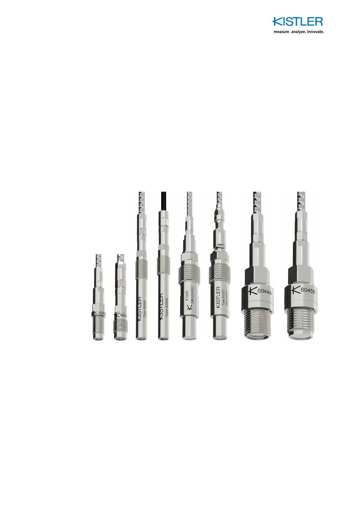
Types 6052 6054 6056 6058 6124 6125 6044 6045
Fig. 1: Uncooled cylinder pressure sensors
2.1 Technical data and documentation
Data sheets are available on www.kistler.com.

Uncooled piezoelectric pressure sensors
6052_002-839-12.20
Page 6
2.2 Principle of operation
The sensor membrane converts the measured pressure
into a force which is applied to the piezoelectric measu-
ring element. In the piezoelectric crystal package this
force generates an electrostatic charge proportional to the
load. An electrode collects this charge and supplies it to
the sensor connector, then via the piezoelectric cable; the
chargeamplierconvertsthischargeintoanelectricvol-
tage for measurement and processing.
The piezoelectric principle is suitable for measurements
of fast, dynamic and quasi-static pressure changes and
thus plays a key role in engine pressure measurements.
Fig. 2: Structure of a front sealing sensor Type 6052

Installation of the piezoelectric sensor
Page 7
6052_002-839-12.20
3. Installation of the piezoelectric sensor
3.1 General information
The accuracy of a measurement and quality of the data
are highly dependent on careful installation of the piezo-
electric pressure sensor.
Thesensorboremustbemachinedtothespeciedtole-
rances.
Thespeciedtighteningtorqueofthepiezoelectricsensor
must be observed.
The sensor installation plays a critical part in contributing
to the overall accuracy and performance of the measu-
rement chain itself. So a good understanding of the ins-
tallation types and their strengths and weaknesses is es-
sential information for the measurement and development
engineer.
Sensors can be classied in several ways. In this do-
cument, relating to uncooled sensors, we shall look at
sealing and installation securing technologies as the main
differentiators. This means whether the sensor is front
sealed or shoulder sealed. In combination with threaded
or plug-in securing methods.
When planning the installation, it is possible with certain
types, to consider the amount of recession of the sensor
membrane itself relative to the inner cylinder head surface.
Thiscanhaveconsiderablebenetswithrespecttosensor
temperature management - but must be traded off with the
potential that the additional volume in front of the mem-
brane can act as a resonator at certain conditions - thus
adding undesirable high frequencies to the measured data
atspecicspeedsorloadoperatingpointsattheengine.
Fig. 3: Volume in front of sensor membrane

Uncooled piezoelectric pressure sensors
6052_002-839-12.20
Page 8
As a general rule 8mm, threaded (Type 6044/6045) and 1/4
inch plug-in sensor (Type 6124/6125) from Kistler can be
completelyushmountedifdesired.However,aslightre-
cess of up to 2 mm can help considerably with sensor du-
rability, without creating a resonance in a frequency range
which is problematic for engine measurement applications.
Plug-in sensors (Type 6124/6125) are particularly sensi-
tive to machining bore tolerances. This is due to the fact
that the smooth, larger bore is used to correctly position
the sensor concentrically, before the clamping device is
applied. Any mis-alignment will create potential of incor-
rect sealing, excessive localised heat build-up and prema-
ture failure of the sensor itself.
Fig. 4: Sensor Type 6124/6125 bore machining requi-
rements
Front sealed sensors will always require some structural
material at the front of the sensor in order to provide and
support the sealing surface itself. This fact inevitably me-
ans that a front sealed sensor cannot be mounted ush
with the cylinder head surface - there must always be vo-
lume in front of the membrane. The size of this volume
depends upon the material surrounding the sensor instal-
lation - as higher strength material can provide the requi-
red support with less material and thus a smaller volume
in front of the membrane.
Fig. 5: Front seal sensor, dead volume in front of
membrane

Installation of the piezoelectric sensor
Page 9
6052_002-839-12.20
As a general rule, for aluminum, up to 4 mm of material is
required to support the sealing face, whereas steel or cast
iron needs approximately 2.5 mm. The effect of this vo-
lume needs to be considered and understood well - with
respect to the measurement application and data quality -
as an example - 3 mm of material means a „pipe“ of 3 mm
diameter and length is created in front of the membrane.
Typically this dimension gives a resonant frequency of ap-
proximately 30 kHz.
3.2 Direct installation
Direct installation requires the least installation space.
A direct installation is only possible if it is not necessary
to cross any water or oil galleries in the cylinder head cas-
ting.
In the case of repeated mounting and dismounting of
the sensor, there is the risk of damaging the sealing me-
chanism and thread of the mounting bore. Typically, the
cylinder head material is softer than that of the sensor.
Before mounting the sensor in the bore, also to facilitate
dismounting it at the end of the test, it is recommended to
coat thread and sealing part of the piezoelectric sensor
with high temperature resistant grease. Do not apply any
grease on the membrane.
3.3 Installation with sleeve
In the case where the cylinder can only be accessed via
an oil or cooling water gallery, a mounting sleeve is ne-
cessary to provide adequate sealing for the installation. At
the front, the sleeve is screwed and sealed with a sealing
ring, at the rear, sealing is achieved using O-rings and/or
Loctite compound (Loctite 648 for shaft-hub, Loctite 290
for thread).
Benetsofusingamountingsleeve:
Precise sensor bore inside the sleeve
Machining of the bore for the mounting sleeve is sim-
plied
The mounting sleeve has the required strength to en-
sure that the sealing part can resist wear. This allows
the sensor to be mounted and dismounted repeatedly
without restrictions
When removing the sensor, the mounting sleeve pre-
ventscoolinguidfromleakingintocombustioncham-
ber

Uncooled piezoelectric pressure sensors
6052_002-839-12.20
Page 10
Disadvantages of using a mounting sleeve:
Can inuence the cylinder head cooling performance
(depending on size and position of the sleeve with res-
pect to the water cooling channels)
3.4 Installation examples
Fig. 6: Left direct mounting of shoulder sealing sensor,
Middle: sleeve mounting of shoulder sealing
sensor, Right: direct mounting of front sealing
sensor
3.5 Machining the mounting bore
When preparing the sensor bore, ensure that the thread
is concentric in relation to its individual steps. The sealing
part must be completely at. Refer to the specications
and tolerances stated on the datasheet of the sensor.
All machining steps with the drill, milling cutter, reamer
and screw tap must be performed with the work held se-
curely in the same position.
It is important to consider that the sealing surface has two
functions - in addition to the pressure seal, this surface
provides a heat transfer path for the sensor itself. For
front sealed sensors this is particularly critical as the seal
is in front of the measuring element - and thus directs heat
away from the measuring element itself. This is part of the
sensor temperature management strategy in the design of

Installation of the piezoelectric sensor
Page 11
6052_002-839-12.20
the sensor. So any compromise at the sealing surface can
cause an undesirable increase in operating temperature
that can affect data quality - and reduce sensor life.
As mentioned above, plug-in sensors (Type 6124/6125)
are particularly sensitive to machining bore tolerances. It
is essential to use the correct machining tools and me-
thods for creating the sensor bore and installation. This
will provide a good quality installation with correct, con-
centric positioning of the sensor and a high quality sealing
surface for optimised sensor operation.
Fig. 7: MountingborespecicationofsensorType
6124/6125, for mounting nipple
Fig. 8: Step drill Type 1337A for mounting nipple
M10x1
Fig. 9: Screw tap Type 1353 for mounting nipple M10x1

Uncooled piezoelectric pressure sensors
6052_002-839-12.20
Page 12
3.6 Check points before installation
Piezoelectric cable – If the piezoelectric cable con-
nected to the sensor is loose it must be retightened
and made secure.
Carefully check the piezoelectric cable for damage
over its full length, and if necessary replace it comple-
tely if any mechanical damage is evident. The insulati-
on resistance of sensor and piezoelectric cable should
be checked by connecting the insulation tester at the
end of the piezoelectric cable. The minimum require-
mentatroomtemperatureis10E13Ω.
Sensor seal ring – The sensor seal ring must always
be applied to the shoulder sealing sensor as shown in
Figure 4. If the sealing ring is damaged, it should be re-
placed. Front sealing sensors are mounted without any
sealingring-hencethesurfacenishrequirementsare
critical.
.
Fig. 10: Seal ring of a shoulder sealing sensor Type
6045
Mounting bore – Check the condition of the mounting
bore and sealing face; it must be machined to the spe-
cied dimensions and tolerances as described in the
datasheet, and also clean and dry prior to installation.
Fig. 11: Sealing surface within the installation bore of
M5 sensor
Installation of the piezoelectric sensor
Page 13
6052_002-839-12.20
The sealing face and mounting bore should be considered
a service item during the lifetime of the sensor installation.
The sealing face in particular requires maintenance and
inspection. For this purpose a borescope should be used
to evaluate the sealing surface during service. This allows
inspection of the seal and determination of any leakage,
or imperfections in the installation itself.
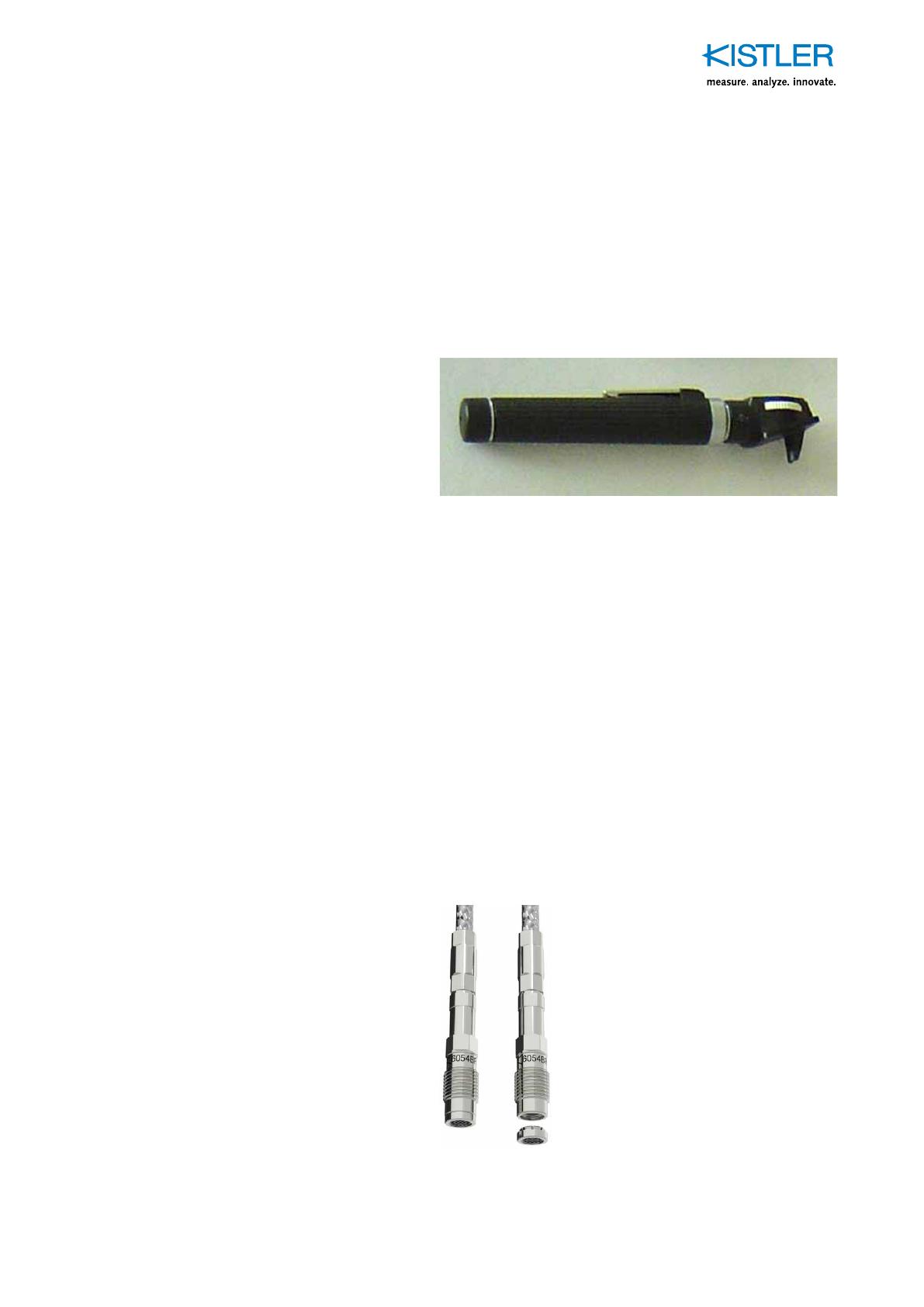
Fig. 12: A handheld optical boresope suitable for inspec-
ting the sensor installation and sealing surface
3.7 Flameguard for M5 sensors
Flameguard installation – place the ameguard on
a plane surface, then press the sensor on the ame-
guard. Work with both parts aligned in the same axis,
otherwisetheameguardclipsmaygetdamaged.
Removal of ameguard–theameguardcanbere-
movedwiththengernailpressedinbetweenthegap
ofdiaphragmandameguard.Possibleisalsotheuse
ofatapwrenchtoholdandpulltheameguard.
Do not use any hard tool to separate both parts, other-
wise the sensor diaphragm can be damaged.
Fig. 13: SensorType6054withameguard
Type 6539A1Q01

Uncooled piezoelectric pressure sensors
6052_002-839-12.20
Page 14
4. Installing the sensor into the bore
Feed the piezoelectric cable through the mounting
wrench,and then t the mounting wrench on the hex of
the sensor. Before installing the sensor in the bore, the th-
read and sealing part should be lubricated with high-tem-
perature resistant grease (for example MOLYKOTE HSC
plus or Metaux 70-81). This will facilitate dismounting
the sensor from the bore post-testing. During use, pay at-
tention to protect the sensor’s piezoelectric cable. Do not
squash, twist or pull the piezoelectric cable.
Screw the sensor hand-tight and then use the torque
wrenchfortighteningtotherequiredvalueasspeciedin
the datasheet of the sensor.
Fig. 14: Assembly with sensor and mounting wrench for
installation

Piezoelectric sensor cable routing
Page 15
6052_002-839-12.20
5. Piezoelectric sensor cable routing
The piezoelectric cable of the sensor must be routed to
avoid other high- frequency, or power cables, as much
as possible, e.g. ignition or fuel injection system cabling,
dynamometer or motor power cables. If this cannot be
avoided, the piezoelectric cables should be kept perpen-
dicular to the high-frequency signal lines to reduce signal
interference.
There must be no mechanical tension on the piezoelec-
tric cable. It is absolutely essential to avoid deformation
caused by sharp bends. During use, pay attention to pro-
tect the piezoelectric cable: do not squash, twist or pull
it. Ensure the cleanliness of the piezoelectric cable con-
nector. Do not allow water, oil, dust, or other dirt in the
vicinity of the cable interfaces. If the piezoelectric con-
nector becomes contaminated during use, use an elect-
ronic cleaning spray to clean it. Use the cap to cover and
protect the piezoelectric connector when the piezoelectric
sensor is not in use.

Uncooled piezoelectric pressure sensors
6052_002-839-12.20
Page 16
6. Setting up the measuring chain
6.1 Connecting the piezoelectric cable to charge amplier
Fig. 15: Basic arrangement of a measuring chain
Piezoelectric sensor cable, adapter, and piezoelectric ex-
tension cable should be connected before connecting its
endtotheinputsocketofthechargeamplier.
Makesurethechargeamplierisnotinmeasuringmode
when connecting the piezoelectric sensor cable to the
charge amplier input. This avoids potential damage to
sensitive electronic input circuitry.
The length of piezoelectric cables between sensor and
charge amplier should not exceed 10m. Interference
from extraneous voltages and ground loop issues at the
test cell can be avoided, or reduced, by using a short pie-
zoelectriccableandpositioningthechargeamplierclose
to the piezoelectric sensor.
6.2 Selecting the sensor sensitivity
The sensor is calibrated from production in several pres-
sures and temperature ranges in order to fully characte-
rise the sensor performance with respect to temperature
variation. In addition, this allows the user to select an op-
timum sensitivity according to any expected temperature
range of their measurements.
However, it is often the case that a single value must be
selected as the unit under test maybe operating over a
wide range of conditions - and that a single representative

Setting up the measuring chain
Page 17
6052_002-839-12.20
sensitivity must be used to cover all operation points. In
this case, it is recommended to use a representative tem-
perature value where the sensor typically operates under
most conditions, to select the sensitivity value.
For uncooled sensors of 8 mm and plug-in types this is
recommended as 250 °C. For M5 type sensors, this is re-
commended as 200 °C.

Uncooled piezoelectric pressure sensors
6052_002-839-12.20
Page 18
7. Dismounting and maintenance
7.1 Dismounting
Allow the cylinder head to cool down before removing the
sensor from the mounting bore. Dismount in reverse order
than installation:
Disconnect the piezoelectric sensor cable from the
chargeamplier/fromtheextensioncable.
Feed the piezoelectric sensor cable through the moun-
tingwrench,carefullyslideittothesensor,andthent
the mounting wrench on the hex of the sensor.
Unscrew the sensor from the bore.
7.2 Maintenance
Piezoelectric pressure sensors are precision instruments;
theywilldelivermeasurementsinthespeciedaccuracy
range only if they are handled with care. Special attention
is required for the front part of the sensor – the diaphragm
and sealing area must always be protected against me-
chanical damage.
.
Do not tap impact or shock the front surface of the sensor
with metal or any other objects – this will help to avoid
damage to the membrane.
Visual inspection – Sensor and piezoelectric cable
should be carefully inspected for anomalies (dama-
ge, soot deposits, overheating due to combustion gas
leakage).
Cleaning – After the sensor is disassembled from the
engine, combustion deposits may be cleaned with a
soft brush and Isopropyl alcohol (CAS Number 67-63-0).
The front part of the sensor (membrane) cannot be
cleaned using mechanical means such as brushing,
sand blasting, grinding, etc. as this will irreparably da-
mage the diaphragm and therefore the sensor.
Visual inspection – After cleaning, see above.
Insulation check – The insulation resistance of the
sensor with piezoelectric cable should be checked by
connecting the insulation tester Type 5493 at the end
/


