
1
KB160/KB161 Series
Mini-ITX Industrial Motherboard
User’s Manual
A-304-M-2008

2
Copyright
This publication contains information that is protected by copyright. No part of it may be re-
produced in any form or by any means or used to make any transformation/adaptation without
the prior written permission from the copyright holders.
This publication is provided for informational purposes only. The manufacturer makes no
representations or warranties with respect to the contents or use of this manual and specifi-
cally disclaims any express or implied warranties of merchantability or fitness for any particular
purpose. The user will assume the entire risk of the use or the results of the use of this docu-
ment. Further, the manufacturer reserves the right to revise this publication and make changes
to its contents at any time, without obligation to notify any person or entity of such revisions
or changes.
Changes after the publication’s first release will be based on the product’s revision. The website
will always provide the most updated information.
© 2014. All Rights Reserved.
Trademarks
Product names or trademarks appearing in this manual are for identification purpose only and
are the properties of the respective owners.
FCC and DOC Statement on Class B
This equipment has been tested and found to comply with the limits for a Class B digital
device, pursuant to Part 15 of the FCC rules. These limits are designed to provide reason-
able protection against harmful interference when the equipment is operated in a residential
installation. This equipment generates, uses and can radiate radio frequency energy and, if not
installed and used in accordance with the instruction manual, may cause harmful interference
to radio communications. However, there is no guarantee that interference will not occur in a
particular installation. If this equipment does cause harmful interference to radio or television
reception, which can be determined by turning the equipment off and on, the user is encour-
aged to try to correct the interference by one or more of the following measures:
• Reorient or relocate the receiving antenna.
• Increase the separation between the equipment and the receiver.
• Connect the equipment into an outlet on a circuit different from that to which the receiver
is connected.
• Consult the dealer or an experienced radio TV technician for help.
Notice:
1. The changes or modifications not expressly approved by the party responsible for compli-
ance could void the user’s authority to operate the equipment.
2. Shielded interface cables must be used in order to comply with the emission limits.

3
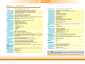
Copyright .............................................................................................................2
Trademarks ........................................................................................................2
FCC and DOC Statement on Class B ..................................................... 2
About this Manual ..........................................................................................4
Warranty ............................................................................................................4
Static Electricity Precautions ......................................................................4
Safety Measures ..............................................................................................4
About the Package .........................................................................................5
Chapter 1 - Introduction .............................................................................6
Specifications ................................................................................................6
Features .......................................................................................................... 7
Chapter 2 - Hardware Installation ................................................9
Board Layout ................................................................................................. 9
System Memory ............................................................................................ 9
Installing the DIMM Module ........................................................................ 10
Jumper Settings ......................................................................................... 11
Clear CMOS Data ........................................................................................ 11
Auto Power-on Select .................................................................................. 12
USB Power Select ....................................................................................... 12
Dimming Mode Select ................................................................................. 13
PS/2 Keyboard/Mouse Select ....................................................................... 13
Panel Power Select ..................................................................................... 14
Backlight Power Select ................................................................................ 14
LCD/Inverter Power Select .......................................................................... 15
SATA DOM Power Select ............................................................................. 15
Digital I/O Power Select .............................................................................. 16
Digital I/O Output State .............................................................................. 16
LVDS Channel and bpp Select ..................................................................... 17
Rear Panel I/O Ports ................................................................................. 18
12V DC-in (default) - KB161 Series .............................................................. 18
Graphics Interfaces ..................................................................................... 19
RJ45 LAN Ports ........................................................................................... 19
USB Ports ................................................................................................... 20
I/O Connectors ........................................................................................... 21
Digital I/O Connector .................................................................................. 21
Digital I/O Power Connector ........................................................................ 21
COM (Serial) Ports ...................................................................................... 21
SATA (Serial ATA) Connectors ...................................................................... 22
SATA (Serial ATA) Power Connectors - KB161 Series ..................................... 22
Cooling Fan Connectors............................................................................... 23
Front Panel Connector ................................................................................ 23
LVDS LCD Panel Connector ......................................................................... 24
LCD/Inverter Power Connector .................................................................... 24
ATX Power Connector - KB160 Series .......................................................... 25
Chassis Intrusion Connector ........................................................................ 25
Expansion Slots .......................................................................................... 26
Installing an EXC Board into the EXC Interface for I/O Expansion ......................... 27
EXC Power Connector ................................................................................. 28
LAN LED Connector .................................................................................... 28
Standby Power LED .................................................................................... 29
Battery ....................................................................................................... 29
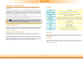
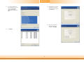
Chapter 3 - BIOS Setup ............................................................... 30
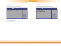
Overview ..................................................................................................... 30
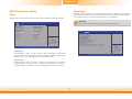
AMI BIOS Setup Utility ............................................................................. 31
Main .......................................................................................................... 31
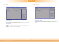
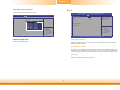
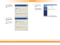
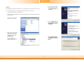
Advanced ................................................................................................... 31
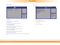
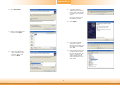
Chipset ...................................................................................................... 41
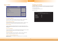
Boot........................................................................................................... 46
Security ...................................................................................................... 47
Save & Exit ................................................................................................ 48
Updating the BIOS .................................................................................... 48
Chapter 4 - Supported Software ........................................................... 49
Chapter 5 - Digital I/O Programming Guide .................................... 57
Appendix A - Troubleshooting ................................................................ 59
Appendix B - Watchdog Sample Code ................................................ 65
Appendix C - System Error Message ................................................... 66
Appendix D - Troubleshooting ................................................................ 67
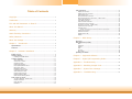
Table of Contents

4
About this Manual
This manual can be downloaded from the website, or acquired as an electronic file included in
the optional CD/DVD. The manual is subject to change and update without notice, and may
be based on editions that do not resemble your actual products. Please visit our website or
contact our sales representatives for the latest editions.
Warranty
1. Warranty does not cover damages or failures that arised from misuse of the product,
inability to use the product, unauthorized replacement or alteration of components and
product specifications.
2. The warranty is void if the product has been subjected to physical abuse, improper instal-
lation, modification, accidents or unauthorized repair of the product.
3. Unless otherwise instructed in this user’s manual, the user may not, under any circum-
stances, attempt to perform service, adjustments or repairs on the product, whether in or
out of warranty. It must be returned to the purchase point, factory or authorized service
agency for all such work.
4. We will not be liable for any indirect, special, incidental or consequencial damages to the
product that has been modified or altered.
Static Electricity Precautions
It is quite easy to inadvertently damage your PC, system board, components or devices even
before installing them in your system unit. Static electrical discharge can damage computer
components without causing any signs of physical damage. You must take extra care in han-
dling them to ensure against electrostatic build-up.
1. To prevent electrostatic build-up, leave the system board in its anti-static bag until you are
ready to install it.
2. Wear an antistatic wrist strap.
3. Do all preparation work on a static-free surface.
4. Hold the device only by its edges. Be careful not to touch any of the components, contacts
or connections.
5. Avoid touching the pins or contacts on all modules and connectors. Hold modules or con-
nectors by their ends.
Safety Measures
To avoid damage to the system:
• Use the correct AC input voltage range.
To reduce the risk of electric shock:
• Unplug the power cord before removing the system chassis cover for installation or servic-
ing. After installation or servicing, cover the system chassis before plugging the power
cord.
Important:
Electrostatic discharge (ESD) can damage your processor, disk drive and other com-
ponents. Perform the upgrade instruction procedures described at an ESD worksta-
tion only. If such a station is not available, you can provide some ESD protection by
wearing an antistatic wrist strap and attaching it to a metal part of the system chas-
sis. If a wrist strap is unavailable, establish and maintain contact with the system
chassis throughout any procedures requiring ESD protection.

5
About the Package
The package contains the following items. If any of these items are missing or damaged,
please contact your dealer or sales representative for assistance.
• One KB160/KB161 motherboard
• One Serial ATA data cable - KB160 Series
• One Serial ATA data with power cable - KB161 Series
• One QR (Quick Reference)
The board and accessories in the package may not come similar to the information listed
above. This may differ in accordance to the sales region or models in which it was sold. For
more information about the standard package in your region, please contact your dealer or
sales representative.
Optional Items
• USB port cable
• Serial ATA data cable
• Serial ATA data with power cable - KB161 Series
• Power adapter (100W, 12V) - KB161 Series
The board and accessories in the package may not come similar to the information listed
above. This may differ in accordance to the sales region or models in which it was sold. For
more information about the standard package in your region, please contact your dealer or
sales representative.
Before Using the System Board
Before using the system board, prepare basic system components.
If you are installing the system board in a new system, you will need at least the following
internal components.
• Memory module
• Storage devices such as hard disk drive, CD-ROM, etc.
You will also need external system peripherals you intend to use which will normally include at
least a keyboard, a mouse and a video display monitor.

6
I/O Connectors
• 1 connector for 2 external USB 2.0/1.1 ports
• 1 vertical USB 2.0/1.1 port* (optional)
• 4 connectors for 4 external serial ports (2.0mm pitch)
- 1 RS485
- 3 RS232
• 1 LVDS LCD panel connector
• 1 LCD/inverter power connector
• 1 8-bit Digital I/O connector
• 1 Digital I/O power connector
• 1 LAN LED connector
• 1 LPC connector
• 2 Serial ATA connectors
• 2 Serial ATA power connectors - KB161 Series
• 1 24-pin ATX power connector - KB160 Series
• 1 front panel connector
• 1 chassis intrusion connector
• 2 fan connectors
WatchDog Timer
• Watchdog timeout programmable via software from 1 to 255 seconds
BIOS
• AMI BIOS
- 32Mbit SPI BIOS
Energy Effi cient
Design
• Supports ACPI
• System Power Management
• Wake-On-Events include:
- Wake-On-PS/2 KB/Mouse* (optional)
- Wake-On-USB KB/Mouse
- Wake-On-LAN
- RTC timer to power-on the system
• AC power failure recovery
Damage Free
Intelligence
• Monitors CPU/system temperature and overheat alarm
• Monitors VCORE/12V/5V/DDR voltages and failure alarm
• Monitors CPU/system fan speed and failure alarm
• Read back capability that displays temperature, voltage and fan speed
Temperature
• Operating: 0
o
C to 60
o
C
• Storage: -20
o
C to 85
o
C
Humidity
• 5% to 95%
Power
Consumption
• TBD
OS Support
• Windows 7 Ultimate x86 & SP1 (32-bit)
• Windows 7 Ultimate x64 & SP1 (64-bit)
• Windows 8 Enterprise x86 (32-bit)
• Windows 8 Enterprise x64 (64-bit)
Dimensions
• Mini-ITX form factor
• 170mm (6.7") x 170mm (6.7")
Chapter 1 - Introduction
Specifications
Processor
• AMD
®
Embedded G-Series SoC FT3 BGA
- 420C: AMD
®
GX420CA, Quad Core, 2M Cache, 2.0GHz, 25W
- 415G: AMD
®
GX415GA, Quad Core, 2M Cache, 1.5GHz, 15W
- 217G: AMD
®
GX217GA, Dual Core, 1M Cache, 1.65GHz, 15W
- 210H: AMD
®
GX210HA, Dual Core, 1M Cache, 1.0GHz, 9W
• 28nm process technology
System Memory
• Two 204-pin DDR3/DDR3L SODIMM sockets
• Supports DDR3/DDR3L 1066/1333/1600MHz
• Supports up to 8GB system memory
• DRAM device technologies: 1Gb, 2Gb and 4Gb DDR3L DRAM technologies are
supported for x8 and x16 devices, unbuffered, non-ECC
Expansion
Interfaces
• 1 PCIe x4 slot
• 1 DFI Proprietary Extension Bus for PCIe/PCI expansion
• 1 Mini PCIe slot
- Supports USB and PCIe signals
- Supports mSATA (optional)
- Supports full size Mini PCIe card
• 1 DFI EXC interface for I/O expansion
- 1 PCIe x1
- 1 High Defi nition Audio
- 2 Serial ports
- 1 PS/2 keyboard/mouse
- 1 USB 2.0
- 1 SMBus
- 1 LPC
Graphics
• AMD
®
HD 8000 Series Graphics
• Display ports: VGA, LVDS and DP
• VGA: resolution up to 2560x1600 @60Hz, 24-bit
• LVDS: NXP PTN3460, 24-bit, dual channel, resolution up to 1920x1200 @60Hz
• DP: supports DP++, resolution up to 4096x2160 @30Hz
• Supports hardware acceleration for DirectX 11.1, H.264, MPEG-2, MPEG-4 AVC,
VC-1 and WMV
LAN
• 2 Intel
®
I210 PCI Express Gigabit Ethernet controllers
• Integrated 10/100/1000 transceiver
• Fully compliant with IEEE 802.3, IEEE 802.3u, IEEE 802.3ab
Serial ATA
• 2 SATA 3.0 ports with data transfer rate up to 6Gb/s
- SATA port 1 provides adequate space for SATA DOM
- One multiplexed with mSATA (Mini PCIe)* (optional)
• Integrated Advanced Host Controller Interface (AHCI) controller
Trusted
Platform
Module - TPM*
(optional)
• Provides a Trusted PC for secure transactions
• Provides software license protection, enforcement and password protection
Rear Panel I/O
Ports
• 1 12V DC-in jack (default) or 4-pin power connector (optional) - KB161 Series
• 1 DB-15 VGA port
• 1 DP port
• 2 RJ45 LAN ports
• 2 USB 2.0/1.1 ports
• 2 USB 3.0 ports
Chapter 1
Chapter 1 Introduction www.dfi .com
Note:
*Optional and is not supported in standard model. Please contact your sales represen-
tative for more information.

7
Chapter 1
Chapter 1 Introduction www.dfi .comChapter 1 Introduction
Features
• Watchdog Timer
The Watchdog Timer function allows your application to regularly “clear” the system at the set
time interval. If the system hangs or fails to function, it will reset at the set time interval so
that your system will continue to operate.
• DDR3L
DDR3L is a higher performance DDR3 DRAM interface providing less voltage and higher speed
successor. DDR3L DRAM modules support 1066/1333/1600MHz for DDR modules. DDR3L deliv-
ers increased system bandwidth and improved performance to provide its higher bandwidth
and its increase in performance at a lower power.
• Graphics
The integrated AMD
®
HD 8000 Series graphics engine delivers an excellent blend of graphics
performance and features to meet business needs. It provides excellent video and 3D graphics
with outstanding graphics responsiveness. These enhancements deliver the performance and
compatibility needed for today’s and tomorrow’s business applications. Supports
VGA, LVDS and
DP
interfaces for 3 display outputs.
• PCI Express
PCI Express is a high bandwidth I/O infrastructure that possesses the ability to scale speeds
by forming multiple lanes. The x4 PCI Express lane supports transfer rate of 4 Gigabyte per
second (2 directions).
• Serial ATA
Serial ATA is a storage interface that is compliant with SATA 1.0a specification. With speed of
up to 6Gb/s (SATA 3.0), it improves hard drive performance faster than the standard parallel
ATA whose data transfer rate is 100MB/s. The bandwidth of the SATA 3.0 will be limited by
carrier board design.
• Gigabit LAN
Two Intel
®
I210 PCI Express Gigabit Ethernet controllers support up to 1Gbps data transmis-
sion.
• Wake-On-PS/2
This function allows you to use the PS/2 keyboard or PS/2 mouse to power-on the system.
Important:
The 5V_standby power source of your power supply must support ≥720mA.
• Wake-On-USB
This function allows you to use a USB keyboard or USB mouse to wake up a system from the
S3 (STR - Suspend To RAM) state.
• RTC Timer
The RTC installed on the system board allows your system to automatically power-on on the
set date and time.
• ACPI STR
The system board is designed to meet the ACPI (Advanced Configuration and Power Interface)
specification. ACPI has energy saving features that enables PCs to implement Power Manage-
ment and Plug-and-Play with operating systems that support OS Direct Power Management.
ACPI when enabled in the Power Management Setup will allow you to use the Suspend to RAM
function
.
With the Suspend to RAM function enabled, you can power-off the system at once by pressing
the power button or selecting “Standby” when you shut down Windows® without having to
go through the sometimes tiresome process of closing files, applications and operating system.
This is because the system is capable of storing all programs and data files during the entire
operating session into RAM (Random Access Memory) when it powers-off. The operating ses-
sion will resume exactly where you left off the next time you power-on the system.
Important:
If you are using the Wake-On-USB Keyboard/Mouse function for 2 USB ports, the
5V_standby power source of your power supply must support ≥1.5A. For 3 or more
USB ports, the 5V_standby power source of your power supply must support ≥2A.
• Wake-On-LAN
This feature allows the network to remotely wake up a Soft Power Down (Soft-Off) PC. It is
supported via the onboard LAN port or via a PCIe LAN card that uses the PCIe PME (Power
Management Event) signal. However, if your system is in the Suspend mode, you can power-
on the system only through an IRQ or DMA interrupt.
Important:
The 5V_standby power source of your power supply must support ≥720mA.
Important:
The 5V_standby power source of your power supply must support ≥720mA.

8
• Power Failure Recovery
When power returns after an AC power failure, you may choose to either power-on the system
manually or let the system power-on automatically.
• USB
The system board supports the new USB 3.0. It is capable of running at a maximum transmis-
sion speed of up to 5 Gbit/s (625 MB/s) and is faster than USB 2.0 (480 Mbit/s, or 60 MB/s)
and USB 1.1 (12Mb/s). USB 3.0 reduces the time required for data transmission, reduces
power consumption, and is backward compatible with USB 2.0. It is a marked improvement
in device transfer speeds between your computer and a wide range of simultaneously
accessible external Plug and Play peripherals.
Chapter 1
Chapter 1 Introduction www.dfi .com

www.dfi .com
9
Chapter 2 Hardware Installation
Chapter 2
Chapter 2 - Hardware Installation
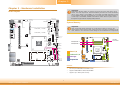
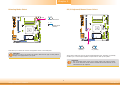
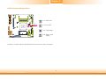
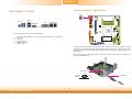
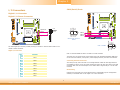
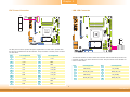
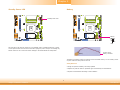
Board Layout
System Memory
Features
Important:
Electrostatic discharge (ESD) can damage your board, processor, disk drives, add-in
boards, and other components. Perform installation procedures at an ESD workstation
only. If such a station is not available, you can provide some ESD protection by wear-
ing an antistatic wrist strap and attaching it to a metal part of the system chassis. If
a wrist strap is unavailable, establish and maintain contact with the system chassis
throughout any procedures requiring ESD protection.
Important:
When the Standby Power LED lights red, it indicates that there is power on the
system board. Power-off the PC then unplug the power cord prior to installing any de-
vices. Failure to do so will cause severe damage to the motherboard and components.
Rear I/O
Onboard I/O
Storage
Expansion
DC-in
+12V 4-pin
power (optional)
DisplayPort
SPI Flash
BIOS
1
2
1
ON
1
LAN 1
LAN 2
1
Chassis
Intrusion
1
1
SATA 0
1
SATA 1
Mini PCIe
1
210
9
1
210
9
1
210
9
1
210
9
1
1
2
Battery
1
LCD/Inverter
Power
Digital I/O
1
AMD
G-Series SoC
Digital I/O
Power
PS/2 Keyboard/Mouse
Power Select (JP5)
Clear CMOS
Data (JP1)
1
USB 2-3 Power
Select (JP12)
1
Dimming Mode
Select (JP10)
1
USB3.0 0-1
Power Select
(JP11)
1
1
1
Buzzer
21
39
40
1
12
11
12
USB 0-1
USB 0
USB 1
VGA
1
1
1
DIO 0-3
Output State
(JP15)
DIO Power
Select (JP14)
Backlight Power
Select (JP7)
Auto Power-on
Select (JP2)
EXC
EXC
Power
1
USB2.0 0-1
Power Select
(JP13)
USB 3.0
USB 2.0
LVDS Channel
and bpp Select
(SW1)
DIO 4-7
Output State
(JP16)
SATA 3.0
USB 2.0
910
12
USB 2-3
PTN3460
LVDS LCD
Panel
DDR3/DDR3L_1 SODIMM
DDR3/DDR3L_2 SODIMM
COM 1
COM 3
COM 2
COM 4
Front
Panel
1
2
5
6
Panel Power
Select (JP8)
System Fan
Standby
Power LED
12 24
113
19 20
1
4
ATX
Power
LCD/Inverter
Power Select
(JP9)
1
4
CPU Fan
12
ISL62771
SATA
Power 0
SATA
Power 1
LPC
1
12
2
11
LAN1 State
LAN2 State
LAN2 State
1
LAN1 State
2
78
SATA DOM
Power
Select
(JP6)
Note:
SATA1 supports SATA DOM.
PCIe x4
DFI Proprietary
Extension Bus
DDR3/DDR3L-2
DDR3/DDR3L-1
Standby
Power LED
• Two 204-pin DDR3/DDR3L SODIMM sockets
• Supports DDR3/DDR3L 1066/1333/1600MHz
• Supports up to 8GB system memory

www.dfi .com
10
Chapter 2 Hardware Installation
Chapter 2
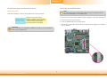
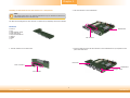
Installing the DIMM Module
1. Make sure the PC and all other peripheral devices connected to it has been powered down.
2. Disconnect all power cords and cables.
3. Locate the SODIMM socket on the system board.
4. Note the key on the socket. The key ensures the module can be plugged into the socket in
only one direction.
Note:
The system board used in the following illustrations may not resemble the actual
board. These illustrations are for reference only.
The system board supports the following memory interface.
Single Channel (SC)
Data will be accessed in chunks of 64 bits (8B) from the memory channels.
Single Channel
DIMMs are on the same channel.
DIMMs in a channel can be identical or
completely different. However, we highly
recommend using identical DIMMs.
Not all slots need to be populated.
Important:
If you are installing one DDR3/DDR3L SODIMM only, make sure that the SODIMM 2
socket must be populated first.

www.dfi .com
11
Chapter 2 Hardware Installation
Chapter 2
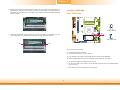
6. Push down the module until the clips at each end of the socket lock into position. You will
hear a distinctive “click”, indicating the module is correctly locked into position.
Clip
5. Grasping the module by its edges, align the module into the socket at an approximately 30
degrees angle. Apply firm even pressure to each end of the module until it slips down into
the socket. The contact fingers on the edge of the module will almost completely disappear
inside the socket.
Clip
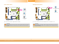
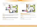
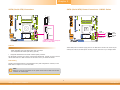
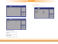
Jumper Settings
Clear CMOS Data
If you encounter the following,
a) CMOS data becomes corrupted.
b) You forgot the supervisor or user password.
you can reconfigure the system with the default values stored in the ROM BIOS.
To load the default values stored in the ROM BIOS, please follow the steps below.
1. Power-off the system and unplug the power cord.
2. Set JP1 pins 2 and 3 to On. Wait for a few seconds and set JP1 back to its default setting,
pins 1 and 2 On.
3. Now plug the power cord and power-on the system.
2-3 On:
Clear CMOS Data
1-2 On:
Normal (default)
JP1
3
1
2
3
1
2

www.dfi .com
12
Chapter 2 Hardware Installation
Chapter 2
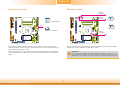
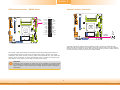
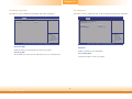
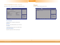
Auto Power-on Select
JP2 is used to select the method of powering on the system. If you want the system to
power-on whenever AC power comes in, set JP2 pins 2 and 3 to On. If you want to use the
power button, set pins 1 and 2 to On.
When using the JP2 “Power On” feature to power the system back on after a power failure
occurs, the system may not power on if the power lost is resumed within 5 seconds (power
flicker).
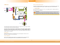
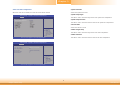
JP11, JP12 and JP13 are used to select the power of the USB ports. Selecting +5V_standby
will allow you to use a USB device to wake up the system.
USB Power Select
Important:
If you are using the Wake-On-USB Keyboard/Mouse function for 2 USB ports, the
+5V_standby power source of your power supply must support ≥1.5A. For 3 or more
USB ports, the +5V_standby power source of your power supply must support ≥2A.
1-2 On:
Power-on via power button
(default)
2-3 On:
Power-on via AC power
JP2
132
132
132
132
2-3 On:
+5V_standby
1-2 On: +5V
(default)
USB 2.0
2-3 (JP12)
USB 2.0
0-1 (JP13)
USB 3.0
0-1 (JP11)

www.dfi .com
13
Chapter 2 Hardware Installation
Chapter 2
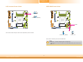
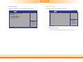
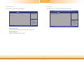
PS/2 Keyboard/Mouse Power Select
JP5 is used to select the power of the PS/2 keyboard/mouse port. Selecting +5V_standby
will allow you to use the PS/2 keyboard or PS/2 mouse to wake up the system.
Important:
1. The +5V_standby power source of your power supply must support ≥720mA.
2. JP5 will be used when an EXC board is installed into the EXC interface on the
motherboard for I/O expansion.
JP5
2-3 On:
+5V_standby
1-2 On: +5V
(default)
132
132
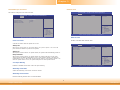
Dimming Mode Select
JP10 allows you to select the mode for the lightness control of the LVDS panel.
2-3 On: Voltage Mode
(default)
1-2 On: PWM Mode
312
312
Important:
You need to refer to your panel’s user guide to determine the type of mode (PWM or
Voltage) most appropriate for your panel.
JP10

www.dfi .com
14
Chapter 2 Hardware Installation
Chapter 2
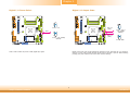
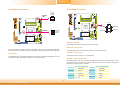
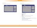
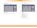
Backlight Power SelectPanel Power Select
1-2 On: +12V
3-4 On:+5V
5-6 On: +3.3V
(default)
2-3 On: +5V
1-2 On: +3.3V (default)
JP8 is used to select the power supplied with the LCD panel.
Important:
Before powering-on the system, make sure that the power settings of JP8 match the
LCD panel’s specification. Selecting the incorrect voltage will seriously damage the
LCD panel.
JP7 is used to select the power level of backlight control: +3.3V (default) or +5V.
Important:
Before powering-on the system, make sure that the power settings of JP7 match the
power specification of backlight control. Selecting the incorrect voltage will seriously
damage the backlight.
6
4
2
5
3
1
JP8
6
4
2
5
3
1
6
4
2
5
3
1
JP7
3
1
2
3
1
2

www.dfi .com
15
Chapter 2 Hardware Installation
Chapter 2
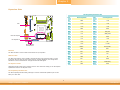
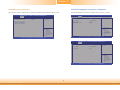
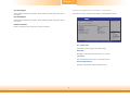
LCD/Inverter Power Select
2-3 On: +5V (default)
1-2 On: +12V
132
132
JP9 is used to select the power level of the LCD/Inverter power connector.
SATA DOM Power Select
Note:
1. SATA port 1 provides adequate space for SATA DOM.
2. When SATA port 1 does not operate as the SATA DOM device, JP6 must be set to
pins 1-2.
JP6 is used to select the power level of SATA DOM.
1-2 On: GND (default) 2-3 On: +5V
JP6
SATA 1
1
3
2
1
3
2
JP9

www.dfi .com
16
Chapter 2 Hardware Installation
Chapter 2
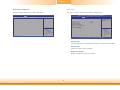
Digital I/O Power Select
2-3 On: +5V_standby
(default)
1-2 On: +5V
JP14 is used to select the power of DIO (Digital I/O) signal.
Digital I/O Output State
Based on the power level of DIO (Digital I/O) selected on JP14, JP15 (DIO pin 0-3) and JP16
(DIO pin 4-7) are used to select the state of DIO output: pull high or pull low. When selecting
pull high, the power selection will be the same as JP14’s setting.
2-3 On: GND
1-2 On: +5V or
+5V_standby
(default)
1
3
2
1
3
2
1
3
2
1
3
2
JP14
DIO 4-7
(JP16)
DIO 0-3
(JP15)

www.dfi .com
17
Chapter 2 Hardware Installation
Chapter 2
OFF
1 On: Single LVDS
1 Off: Dual LVDS
2 On: VESA (24bpp)
OFF
2 Off: JEIDA or VESA
(18bpp)
The Switch 1 is used to select the LVDS channel and the color of bits per pixel on the system.
LVDS Channel and bpp Select
SW1

www.dfi .com
18
Chapter 2 Hardware Installation
Chapter 2
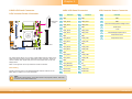
Rear Panel I/O Ports
The rear panel I/O ports consist of the following:
• 1 12V DC-in jack (default) or 4-pin power connector (optional) - KB161 Series
• 1 VGA port
• 1 DP port
• 2 RJ45 LAN ports
• 2 USB 2.0/1.1 ports
• 2 USB 3.0 ports
USB 3.0
12V DC-in (default) - KB161 Series
DC-in
This jack provides maximum of 100W power and is considered a low power solution. Connect
a DC power cord to this jack. Use a power adapter with 12V DC output voltage. Using a volt-
age higher than the recommended one may fail to boot the system or cause damage to the
system board.
The 12V DC-in jack on the system board co-lays with a 4-pin power connector (optional) as
the figure displayed below.
DC-in jack
4-pin power
USB 2.0
DC-in
1
3
24
Ground
Ground
+12V
+12V
VGA
LAN 1 LAN 2
DisplayPort

www.dfi .com
19
Chapter 2 Hardware Installation
Chapter 2
VGA
Graphics Interfaces
The display ports consist of the following:
• 1 VGA port
• 1 DisplayPort
VGA Port
The VGA port is used for connecting a VGA monitor. Connect the monitor’s 15-pin D-shell cable
connector to the VGA port. After you plug the monitor’s cable connector into the VGA port,
gently tighten the cable screws to hold the connector in place.
DisplayPort
The DisplayPort is a digital display interface used to connect a display device such as a com-
puter monitor. It is used to transmit audio and video simultaneously. The interface, which is
developed by VESA, delivers higher performance features than any other digital interface.
Driver Installation
Install the graphics driver. Refer to chapter 4 for more information.
RJ45 LAN Ports
LAN 1
Features
• 2 Intel
®
I210 PCI Express Gigabit Ethernet controllers
The LAN ports allow the system board to connect to a local area network by means of a
network hub.
BIOS Setting
Configure the onboard LAN in the Advanced menu of the BIOS. Refer to chapter 3 for more
information.
Driver Installation
Install the LAN drivers. Refer to chapter 4 for more information.
LAN 2
LAN 1
LAN 2
DisplayPort

www.dfi .com
20
Chapter 2 Hardware Installation
Chapter 2
USB Ports
These USB devices allow data exchange between your computer and a wide range of simulta-
neously accessible external Plug and Play peripherals.
The system board is equipped with two onboard USB 3.0 ports (USB 0-1) and two onboard
USB 2.0 ports (USB 0-1). The 10-pin connector allows you to connect 2 additional USB 2.0
ports (USB 2-3). The additional USB port may be mounted on a card-edge bracket. Install the
card-edge bracket to an available slot at the rear of the system chassis and then insert the
USB port cables to a connector.
BIOS Setting
Configure the onboard USB in the Advanced menu (“USB Configuration” submenu) of the
BIOS. Refer to chapter 3 for more information.
Driver Installation
You may need to install the proper drivers in your operating system to use the USB device.
Refer to your operating system’s manual or documentation for more information.
USB 1
USB 0
USB 2.0
10
VCC
-Data
+Data
GND
Key
VCC
-Data
+Data
GND
N. C.
9
12
USB 2.0
USB 3.0
USB 2-3
Important:
If you are using the Wake-On-USB Keyboard/Mouse function for 2 USB ports, the
+5V_standby power source of your power supply must support ≥1.5A. For 3 or more
USB ports, the +5V_standby power source of your power supply must support ≥2A.
Wake-On-USB Keyboard/Mouse
The Wake-On-USB Keyboard/Mouse function allows you to use a USB keyboard or USB mouse
to wake up a system from the S3 (STR - Suspend To RAM) state. To use this function:
• Jumper Setting
JP11, JP12 and JP13 must be set to “2-3 On: +5V_standby”. Refer to “USB Power Select” in
this chapter for more information.
USB 0
USB 1
Page is loading ...
Page is loading ...
Page is loading ...
Page is loading ...
Page is loading ...
Page is loading ...
Page is loading ...
Page is loading ...
Page is loading ...
Page is loading ...
Page is loading ...
Page is loading ...
Page is loading ...
Page is loading ...
Page is loading ...
Page is loading ...
Page is loading ...
Page is loading ...
Page is loading ...
Page is loading ...
Page is loading ...
Page is loading ...
Page is loading ...
Page is loading ...
Page is loading ...
Page is loading ...
Page is loading ...
Page is loading ...
Page is loading ...
Page is loading ...
Page is loading ...
Page is loading ...
Page is loading ...
Page is loading ...
Page is loading ...
Page is loading ...
Page is loading ...
Page is loading ...
Page is loading ...
Page is loading ...
Page is loading ...
Page is loading ...
Page is loading ...
Page is loading ...
Page is loading ...
Page is loading ...
Page is loading ...
Page is loading ...
-
 1
1
-
 2
2
-
 3
3
-
 4
4
-
 5
5
-
 6
6
-
 7
7
-
 8
8
-
 9
9
-
 10
10
-
 11
11
-
 12
12
-
 13
13
-
 14
14
-
 15
15
-
 16
16
-
 17
17
-
 18
18
-
 19
19
-
 20
20
-
 21
21
-
 22
22
-
 23
23
-
 24
24
-
 25
25
-
 26
26
-
 27
27
-
 28
28
-
 29
29
-
 30
30
-
 31
31
-
 32
32
-
 33
33
-
 34
34
-
 35
35
-
 36
36
-
 37
37
-
 38
38
-
 39
39
-
 40
40
-
 41
41
-
 42
42
-
 43
43
-
 44
44
-
 45
45
-
 46
46
-
 47
47
-
 48
48
-
 49
49
-
 50
50
-
 51
51
-
 52
52
-
 53
53
-
 54
54
-
 55
55
-
 56
56
-
 57
57
-
 58
58
-
 59
59
-
 60
60
-
 61
61
-
 62
62
-
 63
63
-
 64
64
-
 65
65
-
 66
66
-
 67
67
-
 68
68


Ask a question and I''ll find the answer in the document
Finding information in a document is now easier with AI
Related papers
Other documents
-
 Cables Direct RB-432 Datasheet
-
Diamond Systems Aries User manual
-
SYBA SY-ADA24029 User manual
-
 IBASE Technology Signature Book SI-22 Series User manual
-
Vosstronics TIP-M401ST-BK Datasheet
-
Eurotech CPU-162-22 Owner's manual
-
AXIOMTEK ICO100-839 User manual
-
Toshiba USB001Z User manual
-
ECS Liva X User manual
-

