Page is loading ...

Passionate about Music
w w w . B e t t e r M u s i c B u i l d e r . c o m
Thank you for purchasing this unit. To
make full and effective use of this unit,
please read this Owner's Manual
carefully before operating it. Please
retain this manual for future reference.
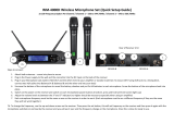
Professional UHF Wireless Microphone System
VM-92U G5
Operating Instructions
Passionate about Music
Better Music Builder .com
®
110421
UHF
Frequency Selectable
2-in-1 Base Module
***
1 Receive Module with 2 Wireless Microphones System
UHF WIRELESS SYSTEM VM-92U G5
602.00
10mW
MHz
UHF WIRELESS SYSTEM VM-92U G5
627.00
10mW
MHz
PO WER
iR
VM-92 U G5
UP
SE T
DOWN
MIC 2
UP
SET
DOWN
MIC 1
2- IN-1 BASE RECE IVER MOD ULEDUA L CH ANNE L REC EIV ER
UHF
AF CH IRFRQ SCAN
RF
B
602.000
MHZ
BAT
SQGRP AF CH IRFRQ SCAN
RF
B
627.000
MHZ
BAT
SQGRP

CONTENTS
INTRODUCTION................................................................................ 1
SYSTEM FEATURES............................................................................. 1
PACKAGE ACCESSORIES................................................................... 2
2-in-1 BASE MODULE........................................................................ 3
• Controls and Functions................................................................. 3~5
• Hardware Setup............................................................................. 6~8
HANDHELD MICROPHONE............................................................... 9
• Controls and Functions................................................................ 9~10
• High Tech Auto-Mute System Features.......................................... 11
OPERATION............................................................................... 12~19
• How to Select Frequencies for the Receiver................................. 12
• How to Match Receiver’s Frequency with Microphone............. 13
• How to Select Channel for the Receiver....................................... 14
• How to Adjust Squelch.................................................................... 14
• How to Insert/change Batteries of Microphone.......................... 15
• How to Select Frequency of Microphone..................................... 16
• How to Turn On/Off Microphone................................................. 16
• How to Turn High Tech Auto-Mute On/Off................................. 17
• How to Interchange Microphone Head....................................... 17
• How to Select Microphone Signal Strength (5mW/10mW)...... 18
TECHNICAL SPECIFICATION............................................................ 19
BODY-PACK MICROPHONE (Optional)...................................... 20~21
TROUBLESHOOTING................................................................. 22~23
APPENDIX................................................................................. 24~26
WARRANTY..................................................................................... 27
CONTACT INFORMATION............................................................... 28
Contact Us
hand-held
Base Module
Features
Package
Spec
Appendix
Warranty
Troubleshooting
Body-Pack
Intro
Operation

1
INTRODUCTION
Better Music Builder VM-92U G5 is a fifth generation wireless microphone that
uses the latest UHF wireless technology. Its heavy duty design includes two
handheld microphones with one 2-in-1 Base Module, built-in LCD panel on both
microphones and base unit, aluminum alloy handles, and Wireless Infrared Auto
Sync System.
The VM-92U G5 Dual Wireless Microphones are equipped with a six-axis
gyroscope sensor to be the most intelligent and energy efficient microphones.
Utilizing the sensor, the new High Tech Auto-Mute feature integrated onto the
microphones has the ability to automatically mute itself momentarily when
dropped. This eliminates any unwanted noise in the event the user accidentally
drops the microphone to the ground, providing a much more user friendly
experience. The microphones also has the ability to activate “sleep mode” when
left unattended, therefore greatly increasing the overall battery life.
Each handheld microphone has 100 selectable channels in the 602.000 MHz
to 652.000 MHz frequency range. It comes with a convenient portable
mounting rack, making this system perfect for professional DJ’s and at KTV clubs,
restaurants, coffee shops and churches, etc.
SYSTEM FEATURES
1. Six-axis gyroscope sensor integrated onto each microphone.
2. Energy efficient microphones.
3. High Tech Auto-Mute function activates when falling motion is detected.
4. Sleep mode activates when microphone is left unattended.
5. Equipped with the latest wireless technology and UHF dual-channel in a
2-in-1 Base.
6. Clear LCD screen displays Radio Frequency, Volume, Channel, and
Frequency.
7. Wireless Auto Sync System technology makes setting up a breeze.
8. Clear Voice technology delivers crystal clearer sound just like a wired
microphone.
9. 100 selectable channels for each microphone!
10. Adjustable antennas for better signal receiving.
11. AA batteries for easy usage.
12. Receiver Left / Right squelch knobs.
Features
Intro

PACKAGE ACCESSORIES
The package comes with one 2-in-1 Base Module [Receiver], two handheld
microphones, two receiver antennas, one DC adaptor, one unbalanced audio
cable, and four AA batteries.
Package
2
AUDIO CABLE (FOR MIXED OUTPUT): 1 UNIT
For better quality connections, a XLR
to XLR cable is highly recommended.
Recomme nd
AA
ALKALINE
BATTER Y
AA
ALKALINE
BATTER Y
AA
ALKALINE
BATTER Y
AA
ALKALINE
BATTER Y
AA (1.5V) BATTERY: 4 UNITS
DC POWER ADAPTOR: 1 UNIT
DC-POWER USAGE: This wireless
microphone system is designed specifically
for the North American market, that uses
120V for DC power. For usage in Asia or
Europe, please change it to 220V by an
adaptor with DC 14V output 500mA.
NOTE
2-IN-1 BASE MODULE [RECEIVER]: 1 UNIT
HANDHELD MICROPHONE: 2 UNITS
RECEIVER
ANTENNA:
2 UNITS
10.2 inches
25.8 cm
UHF WIRELESS SYSTEM VM-92U G5
10mW
10mW
MHz
UHF WIRELESS SYSTEM VM-92U G5
10mW
10mW
MHz
POWER
iR
VM-92U G5
UP
SE T
DOWN
MI C 2
UP
SET
DOWN
MI C 1
2- I N -1 BA S E R E C EIVER MO D ULEDU A L C H A NNE L R E C EIVER
UHF
AF CH IRFRQ
SQGRP
SCANRF
MHZ
BAT
B
AF CH IRFRQ
SQGRP
SCANRF
MHZ
BAT
B

POWER
iR
VM-92U G5
UP
SE T
DOWN
MI C 2
UP
SET
DOWN
MI C 1
2- I N -1 BA S E R E C EIVER MO D ULEDU A L C H A NNE L R E C EIVER
UHF
AF CH IRFRQ
SQGRP
SCANRF
MHZ
BAT
B
AF CH IRFRQ
SQGRP
SCANRF
MHZ
BAT
B
Base Module
3
2-in-1 BASE MODULE [RECEIVER]
CONTROLS AND FUNCTIONS
FRONT PANEL:
1. MIC 1 SELECTOR BUTTONS (UP/SET/DOWN): Allows control of LCD
screen and its functions.
2. MIC 1 LCD SCREEN: Displays MIC 1 system status.
3. POWER BUTTON: Turns the system on/off.
4. IR PORT: Infrared port for the Wireless Infrared Auto Sync System. Pointing
the handheld microphone’s infrared port at the receiver’s infrared port to
allow communication.
5. MIC 2 LCD SCREEN: Displays MIC 2 system status.
6. MIC 2 SELECTOR BUTTONS (UP/SET/DOWN): Allows control of LCD
screen and its functions.
1 62 53 4

AF CH IRFRQ
SQGRP
SCANRF
MHZ
BAT
B
LCD PANEL:
After turning on the “POWER” button, LCD screen will display the following:
7. ANTENNA A/B: Displays the antenna in use.
8. RADIO FREQUENCY: Strength indicator of radio signal.
9. AUDIO FREQUENCY: Strength indicator of incoming audio signal.
10. SQ: *Coming soon to next generation models
11. CHANNEL & SELECT: Displays current channel & Selector for channel.
12. FREQUENCY SELECT: Selects frequency.
13. SCAN: Scans for microphone frequency.
14. INFRARED SCAN: Scans for microphone Infrared frequency.
15. SQ: *Coming soon to next generation models
16. BATTERY STATUS: Displays microphone battery status.
17. FREQUENCY: Displays current frequency.
4
16 1714 1513121110987

ANTENNA -B ANTENNA -AMIC 2 SQUEL CH
MA X MIN MA X MIN
MIC 1 SQUEL CH
DC 14V
DC-POWER
MIC 2 BALANCED MIC 1 BALANCED
TRUE DIVERSITY
MIX
MIC 1 & 2
UNBAL AN CED
AU D I O OUTPU T
364160510000
Model No.: VM-92U G5
CALIFORNIA, UNITED STATES OF AMERIC A
w w w. Be tt e r Mu si cB u il de r . c om
ENGINEERED AND DESIGN IN U.S.A.
Better Music Builder
®
®
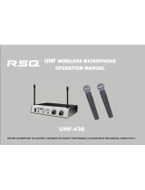
REAR PANEL:
16. ANTENNA-B: Connect the antenna to the BNC socket.
17. MIC 2 SQUELCH CONTROL: Sensitivity adjustment. Higher level equals
longer coverage.
18. MIXED OUTPUT: Unbalanced 1/4" audio output for MIC 1 & MIC 2.
19. MIC 2 BALANCED OUTPUT: Balanced XLR audio output.
20. MIC 1 BALANCED OUTPUT: Balanced XLR audio output.
21. POWER SUPPLY: Removable adapter with DC14~22V 500mA.
22. MIC 1 SQUELCH CONTROL: Sensitivity adjustment. Higher level equals
longer coverage.
23. ANTENNA-A: Connect the antenna to the BNC socket.
16 17 18 19 20 21 22 23
5

6
ANTENNA -B ANTENNA -AMIC 2 SQUEL CH
MA X MIN MA X MIN
MIC 1 SQUEL CH
DC 14V
DC-POWER
MIC 2 BALANCED MIC 1 BALANCED
TRUE DIVERSITY
MIX
MIC 1 & 2
UNBAL AN CED
AU D I O OUTPU T
364160510000
Model No.: VM-92U G5
CALIFORNIA, UNITED STATES OF AMERIC A
w w w. Be tt e r Mu si cB u il de r . c om
ENGINEERED AND DESIGN IN U.S.A.
Better Music Builder
®
®
HARDWARE SETUP
HOW TO CONNECT AUDIO OUTPUT:
There are three rear outputs as shown in the below diagram:
1. Mixed Output
Mixed Output is unbalanced audio output for MIC 1 & MIC 2 using 1/4”
connection. When using this output, MIC 1 and MIC 2 have to share a
signal. To produce different effects on each microphone, MIC 1 and MIC 2
need their own signals which can be done by using XLR connections.
2. Mic 1 Balanced Output
Mic 1 Balanced Output is balanced audio output for MIC 1 using XLR
connection. When using this output, you can change MIC 1 effects without
affecting MIC 2 effects.
3. Mic 2 Balanced Output
Mic 2 Balanced Output is balanced audio output for MIC 2 using XLR
connection. When using this output, you can change MIC 2 effects without
affecting MIC 1 effects.
We highly recommend using balanced XLR connections if the distance between the
microphone receiver and the mixer is more than 10 feet. The grounding of the balanced XLR
connection delivers better quality signal by reducing noise.
Recommend
1
MIXED OUTPUT
(MIC 1 & 2 UNBALANCED)
3
MIC 2 BALANCED OUTPUT (BALANCED XLR)
MIC 1 BALANCED OUTPUT
(BALANCED XLR)
2
Set Up

7
ANTENNA -B ANTENNA -AMIC 2 SQUEL CH
MA X MIN MA X MIN
MIC 1 SQUEL CH
DC 14V
DC-POWER
MIC 2 BALANCED MIC 1 BALANCED
TRUE DIVERSITY
MIX
MIC 1 & 2
UNBAL AN CED
AU D I O OUTPU T
364160510000
Model No.: VM-92U G5
CALIFORNIA, UNITED STATES OF AMERIC A
w w w. Be tt e r Mu si cB u il de r . c om
ENGINEERED AND DESIGN IN U.S.A.
Better Music Builder
®
®
XLR
Balanced Input
XLR
Balanced Input
XLR
Balanced Input
XLR
Balanced Input
1/4"
Unbalanced Input
1/4"
Unbalanced Input
1/4"
Unbalanced Input
1/4"
Unbalanced Input
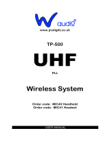
UHF WIRELESS SYSTEM DIAGRAM:
BALANCED CONNECTION
AUDIO MIXER AMPLIFIER OR A KARAOKE UNIT INPUT TERMINAL
REAR VIEW
MIC 2 HANDHELD MICROPHONEMIC 1 HANDHELD MICROPHONE
ANTENNA -B ANTENNA -AMIC 2 SQUEL CH
MA X MIN MA X MIN
MIC 1 SQUEL CH
DC 14V
DC-POWER
MIC 2 BALANCED MIC 1 BALANCED
TRUE DIVERSITY
MIX
MIC 1 & 2
UNBAL AN CED
AU D I O OUTPU T
364160510000
Model No.: VM-92U G5
CALIFORNIA, UNITED STATES OF AMERIC A
w w w. Be tt e r Mu si cB u il de r . c om
ENGINEERED AND DESIGN IN U.S.A.
Better Music Builder
®
®
HOW TO CONNECT DC-POWER:
For North America Market, use 120V, DC 14~22V 500mA adaptor. For market
outside North America, use 220V~ 240V DC adaptor with a maximum battery
capacity of 500mA.
NOTE
Please make sure to use the right DC adaptor. Otherwise, it may damage the 2-in-1 Base
Module and/or the charger because their maximum battery capacity is different. The product
warranty will be voided if there is damage caused by using the wrong DC adaptor.
REAR VIEW

8
OPTIONAL 19” RACK MOUNT KIT:
To put the system onto one of the mount kit, please follow the diagram below.
Our special design feature allows it to be mounted on a DJ rack.
Single Receiver Rack Mount Kit
Dual Receiver Rack Mount Kit
10 inches
19 inches
16.4 inches
Rack mount kit is not included in package.
ANTENNA IS
ADJUSTABLE
10 inches
19 inches
8.2 inches 5.4 inches5.4 inches
POW ER
iR
VM-92U G5
UP
SET
DOWN
MIC 2
UP
SET
DOWN
MIC 1
2-I N-1 B ASE R ECEI VER MODU LEDUA L CHA NNEL REC EIVE R
UHF
AF CH IRFRQ S CAN
RF
B
602.000
MHZ
BAT
SQGRP AF CH IRFRQ S CAN
RF
B
627.000
MHZ
BAT
SQGRP
Rack mount kit is not included in package.
ANTENNA IS
ADJUSTABLE
POW ER
iR
VM-92U G5
UP
SET
DOWN
MIC 2
UP
SET
DOWN
MIC 1
2-I N-1 B ASE R ECEI VER MODU LEDUA L CHA NNEL REC EIVE R
UHF
AF CH IRFRQ S CAN
RF
B
602.000
MHZ
BAT
SQGRP AF CH IRFRQ S CAN
RF
B
627.000
MHZ
BAT
SQGRP
POW ER
iR
VM-92U G5
UP
SET
DOWN
MIC 2
UP
SET
DOWN
MIC 1
2-I N-1 B ASE R ECEI VER MODU LEDUA L CHA NNEL REC EIVE R
UHF
AF CH IRFRQ S CAN
RF
B
602.000
MHZ
BAT
SQGRP AF CH IRFRQ S CAN
RF
B
627.000
MHZ
BAT
SQGRP

UHF WIRELESS SYSTEM VM-92U G5
10mW
10mW
MHz
10mW
10mW
MHz
SET
9
Hand-held
HANDHELD MICROPHONE
CONTROLS AND FUNCTIONS
1. INTERCHANGEABLE MICROPHONE HEAD
2. IR PORT: Infrared port for the Wireless Infrared Auto Sync Technology.
Point the microphone’s infrared port at the receiver’s infrared port to allow
communication.
3. LCD DIGITAL DISPLAY: Displays frequency, battery status and power usage.
4. POWER BUTTON
5. FREQUENCY, HIGH TECH AUTO-MUTE & MIC SIGNAL STRENGTH
SELECTION BUTTON: Press UP/DOWN button to select frequency, high tech
auto-mute function (ON/OFF) and microphone signal strength (5mW/10mW).
6. SET BUTTON: SET button will navigate through the microphone interface.
7. BATTERY SLOTS: Insert 2x1.5V AA battery or 2x1.2V rechargeable battery.
1 3 4
6 5
7
2
AA
ALKALINE
BATTERY
AA
ALKALINE
BATTERY
5

5mW 10mW
MHz
5mW 10mW
MHz
10
LCD PANEL:
After turning on the “POWER”, the LCD screen will light up as below:
1. MICROPHONE SIGNAL STRENGTH: 5mW or 10mW.
The microphone signal strength “5mW/10mW” selection allows the
handheld microphone signal output to be standard at 5mW or strengthened
at 10mW. This feature can improve the audio quality and signal distance
that the handheld microphone can operate in. The standard signal distance
covers 80 feet (25 meters) at 5mW, while at 10mW the signal strength
improves but limits distance coverage to 40 feet (12.5 meters).
2. FREQUENCY: Current value depends on your setting.
3. BATTERY STATUS: Indicates battery life.
BATTERY STATUS:
Indicates full battery on the microphone.
Illustrates the battery status so you can see the
battery strength. A full battery display means
the microphone will last 4~6 hours.
If the microphone cannot turn on, please check the battery. It may be very low. Typical
new full battery life is 4~6 hours with our system, otherwise, the batteries might be defective or
near expiration date. Batteries are not covered under our product warranty.
NOTE
Low Battery
Full Battery
LCD screen will blink
constantly when battery is
extremely low and about
to die.
Indicates low battery on the microphone.
When the microphone LCD screen is blinking
or fading, it’s time to replace the batteries.
5mW
MHz
5mW 10mW
MHz
1
2
3

For more information on “How to Turn Auto-Mute ON/OFF” go to page 17.
NOTE
11
HIGH TECH AUTO-MUTE SYSTEM FEATURES
This function’s primary focus is to eliminate unwanted noise while being energy
efficient. To do so, the microphones are equipped with a six-axis gyroscope
sensor.
FEATURES:
1. Energy Saving
The six-axis gyroscope senses speed in three directions as well as any
angular changes in velocity. This information is transmitted through the sensor
and minimizes power consumption by entering a “sleep mode” when it
senses no movement within a preset time, allowing for more usage time
without changing batteries as often as conventional microphones.
2. Anti-Howl & Noise
To eliminate unwanted noise when the microphone is dropped, the six-axis
gyroscope sensor is used to detect a fast change in motion. The sensor
detects whether the motion is intended or not by the elapsed time it is falling.
When the time (in milliseconds) exceeds an estimated drop, the microphone
signal then cuts off momentarily; so at the point of impact the microphone is
no longer sending any signal to the receiver.
3. Instant “Wake up” Response
The microphone can switch from “sleep mode” to operating mode in
milliseconds with its intelligent sensory technology.
4. Auto-Mute When Not Held
The microphone detects and auto-mutes when it is dropping. This function
can avoid most unwanted noise and greatly decrease the chances of any
damage to the audio equipment. It is important to note the auto mute
function will engage once the sensor detects a falling motion (the minimum
falling distance for the sensor to activate is 12 inches/30 cm). The
microphone will operate normally again once it’s picked up.
Ground
UHF WIRELESS SYSTEM VM-92U G5
10mW
10mW
MHz
12 inches/30 cm

12
OPERATI ON
HOW TO SELECT FREQUENCIES FOR THE RECEIVER
The 2-in-1 Base Module comes with two handheld microphones and the
microphones are preset with 100 frequency channels. The frequency can be
selected either automatically or manually.
1. AUTOMATIC FREQUENCY SELECT
STEP 1: Press “SET” on the receiver and the “CH” will blink.
STEP 2: Press “UP/DOWN” until “SCAN” is blinking and press “SET”. The
receiver will search for the strongest frequency. Wait for “SCAN” to stop blinking.
2. MANUAL FREQUENCY SELECT
STEP 1: Press “SET” on the receiver and the “CH” will blink.
STEP 2: Press “UP/DOWN” until “FRQ” is blinking and press “SET”. While the
frequnecy is blinking, press “UP/DOWN” to select the desired frequency. Wait
for frequency to stop blinking.
Operation
AF
CH IRFRQ SCAN
RF
MHZ
BAT
B
SQGRP
UP
SET
DOWN
MIC 1
UP
SET
DOWN
MIC 1
UP
SET
DOWN
MIC 1
SQGRP
AF
CH IRFRQ SCAN
RF
MHZ
BAT
B
UP
SET
DOWN
MIC 1
UP
SET
DOWN
MIC 1
AF
CH IRFRQ SCAN
RF
MHZ
BAT
B
SQGRP
UP
SET
DOWN
MIC 1
AF
CH IRFRQ SCAN
RF
MHZ
BAT
B
SQGRP

POWER
iR
VM-92U G5
AF
CH IRFRQSCAN
RF
B
MHZ
BAT
AF
CH IRFRQSCAN
RF
MHZ
BAT
A
UP
SET
DOWN
MIC 2
UP
SET
DOWN
MIC 1
2-IN-1 BA SE R ECEIV ER M ODUL EDUAL CHANNEL R ECEI VER
UHF
iR
UP
SET
DOWN
MI C 1
SQGRP
AF
CH IRFRQ SCAN
RF
MHZ
BAT
B
UP
SET
DOWN
MIC 1
AF
CH IRFRQ SCAN
RF
MHZ
BAT
B
SQGRP
UHF WIRELESS SYSTEM VM-92U G5
10mW
10mW
MHz
13
Please make sure that the other handheld microphone is turned off when adjusting the
frequency on one microphone.
Each unit is fully tested and qualified by the manufacturer. However, due to the nature of wireless
connection, interference may occur because of local environments and/or radio signals emitted
by other wireless devices within the household.
NOTE
HOW TO MATCH RECEIVER’S FREQUENCY WITH MICROPHONE
STEP 1: Press “SET” on the receiver and the “CH” will blink.
STEP 2: Press “UP/DOWN” until “IR” is blinking and press “SET”.
STEP 3: While the “IR” light is on, turn ON the microphone, point the
microphone infrared port (IR) directly at the receiver’s IR PORT to initiate the
syncing process.
10mW
10mW
MHz
MICROPHONE AND RECEIVER
FREQUENCY MATCHED
Matching Frequencies
Distance: 3-inch
UP
SET
DOWN
MIC 1
SQGRP
AF
CH IRFRQ SCAN
RF
MHZ
BAT
B
UP
SET
DOWN
MIC 1

14
ANTENNA-B ANTENNA-AM IC 2 SQUEL CH
MAX MIN MAX MIN
MIC 1 SQUELCH
DC 14V
DC-POWER
MIC 2 BALANCED MIC 1 BALANCED
TRUE DIVERS ITY
MIX
MIC 1 & 2
UNBALANCED
AUDIO OUTPU T
364160510000
Model No. : VM-92U G5
CALIFORNIA, UNITED STATES OF AMERICA
www. Be tt e rM usi cB ui ld er .c om
ENGINEERED AND DESIGN IN U.S.A.
Better Music Bui lder
®
®
PLASTIC SCREWDRIVER
MA X MIN
MIC 1 SQUELCH
HOW TO SELECT CHANNEL FOR THE RECEIVER
STEP 1: Press “SET” on the receiver and the “CH” will blink. Press “SET” again
and the channel currently being used will blink.
STEP 2: Press “UP/DOWN” to select the desired channel. Wait for channel to
stop blinking.
HOW TO ADJUST SQUELCH
The SQUELCH knob on the back of the receiver adjusts the sensitivity between
the microphone and the receiver. Use a plastic screwdriver to make the squelch
adjustment. A higher level of squelch allows the usage of microphone further
away from the receiver. However, the drawback of using a higher level of
squelch is the increased chance of interference.
UP
SET
DOWN
MIC 1
AF
CH IRFRQ SCAN
RF
MHZ
BAT
B
SQGRP
UP
SET
DOWN
MIC 1
AF
CH IRFRQ SCAN
RF
MHZ
BAT
B
SQGRP
UP
SET
DOWN
MIC 1

15
HOW TO INSERT/CHANGE BATTERIES OF MICROPHONE
STEP 1: Twist open battery cover.
STEP 2: Use one hand to hold onto the top of the Microphone, and the other
hand to slide 2x1.5V AA batteries into battery slot.
Make sure to follow the polarity of the battery according to the battery
slots.
STEP 3: Twist back battery cover.
Good
AA
ALKALINE
BATTERY
AA
ALKALINE
BATTERY
No Good
AA
ALKALINE
BATTERY
AA
ALKALINE
BATTERY
AA
ALKALINE
BATTERY
UHF WIRELESS SYSTEM VM-92U G5
UHF WIRELESS SYSTEM VM-92U G5

16
UHF WIRELESS SYSTEM VM-92U G5
10mW
10mW
MHz
HOW TO TURN ON/OFF MICROPHONE
TURN ON: Press the power button to turn ON the
microphone. Microphone’s LCD panel will display
microphone power usage, frequency and battery status.
TURN OFF: Press and hold the power button for 3
seconds to turn OFF the microphone.
If the microphone cannot turn on, please check the battery.
It may be very low. Typical new full battery life is 4~6 hours with
our system, otherwise, the batteries might be defective or near
expiration date.
NOTE
HOW TO SELECT FREQUENCY OF MICROPHONE
STEP 1: Power on and remover the battery cover of your handheld microphone.
STEP 2: Using the navigation buttons, use a plastic screwdriver to press “SET”
and the frequency currently being used will blink. Press “▲” UP or “▼” DOWN
buttons to set your preference frequency. Once selected, wait for frequency to
stop blinking.
10mW
10mW
MHz
SET
UHF WIRELESS SYSTEM VM-92U G5
10mW
10mW
MHz
SET
10mW
MHz
SET
PLASTIC SCREWDRIVER

17
HOW TO INTERCHANGE MICROPHONE HEAD
UHF WIRELESS SYSTEM VM-92U G5
10mW
10mW
MHz
2
INTERCHANGEABLE
MICROPHONE HEAD
Replacement parts (such as the
microphone head as shown on the
left) can be purchased from any of
our authorized dealers.
NOTE
1
HOW TO TURN AUTO-MUTE ON/OFF
STEP 1: Power on and remover the battery cover of your handheld microphone.
STEP 2: Using the navigation buttons, use a plastic screwdriver to press “SET”
repeatedly until “9-ON/9-OFF” appears. While blinking, press “▲” UP or “▼”
DOWN buttons to set your preference to “9-ON/9-OFF”. Once selected, wait
for “9-ON/9-OFF” to stop blinking.
10mW
10mW
MHz
SET
UHF WIRELESS SYSTEM VM-92U G5
10mW
10mW
MHz
SET
10mW
MHz
SET
PLASTIC SCREWDRIVER

18
HOW TO SELECT MICROPHONE SIGNAL STRENGTH
(5mW/10mW)
STEP 1: Power on and remover the battery cover of your handheld microphone.
STEP 2: Using the navigation buttons, use a plastic screwdriver to press “SET”
repeatedly until “5mW/10mW” appears. While blinking, press “▲” UP or “▼”
DOWN buttons to set to “5mW/10mW”. Once selected, wait for
“5mW/“10mW” to stop blinking.
The microphone signal strength “5mW/10mW” selection allows the handheld
microphone signal output to be standard at 5mW or strengthened at 10mW.
This feature can improve the audio quality and signal distance that the handheld
microphone can operate in. The standard signal distance covers 80 feet (25
meters) at 5mW, while at 10mW the signal strength improves but limits distance
coverage to 40 feet (12.5 meters).
10mW
10mW
MHz
SET
UHF WIRELESS SYSTEM VM-92U G5
10mW
10mW
MHz
SET
10mW
MHz
SET
PLASTIC SCREWDRIVER
/