Page is loading ...

Installation and Operation
Manual
Model 7300 Modular
Surgery Table
OMI
7300
CA802000
Description
Page 7
Components
Overview
Page 8
Controls &
Indicators
Page 9
Calling For
Service
Page 26
Operation
Page 12
Specifications &
Accessories
Page 26
Operator
Maintenance
Page 25
Installation
Page 4
Important
Information
Page 2
Limited
Warranty
Page 31
Schaerer Medical USA, Inc.

OMI
7100
MODEL
NUMBER
SERIAL
NUMBER
OMI
7100-001
115 VAC
2 AMP 60 HZ
TDWXXXXX
MODEL
INPUT
RATING
SERIAL NO.
CA7681
Owner’s Product Identification
(information that you will need to provide for servicing - key information is highlighted)
Date of Purchase Serial Number
Name of Owner / Facility / Department
Model Number
Name of Authorized SM-USA Dealer Telephone # of Authorized SM-USA Dealer
Address of Authorized SM-USA Dealer

CONTENTS
IMPORTANT INFORMATION.................................................................................................2
Scope and Purpose of This Manual ...............................................................................2
Intended Use of Product.................................................................................................2
Safety Instructions..........................................................................................................2
Explanation of Safety Symbols and Notes......................................................................2
Transportation and Storage Conditions ..........................................................................3
INSTALLATION ......................................................................................................................4
Unpacking.......................................................................................................................4
DESCRIPTION........................................................................................................................7
Introduction.....................................................................................................................7
Features..........................................................................................................................7
COMPONENTS OVERVIEW..................................................................................................8
CONTROLS & INDICATORS .................................................................................................9
OPERATION .........................................................................................................................12
Patient Positions & Weight Capacities..........................................................................12
Head Section, Installation & Operation.........................................................................13
Installing Table Top Sections ........................................................................................13
Possible Pinch Points....................................................................................................14
Pendant Hand Control ..................................................................................................16
Foot Control..................................................................................................................18
Emergency Override Panel...........................................................................................20
Hand Control Display Messages ..................................................................................22
OPERATOR MAINTENANCE ..............................................................................................25
Preventive Maintenance Schedule ...............................................................................25
Cleaning .......................................................................................................................25
CALLING FOR SERVICE.....................................................................................................26
SPECIFICATIONS & ACCESSORIES .................................................................................26
Options and Accessories..............................................................................................27
LIMITED WARRANTY..........................................................................................................31

2
RETURN TO TABLE
OF CONTENTS
IMPORTANT INFORMATION
Scope and Purpose of This Manual
This manual covers complete instructions for the installation, operation, and nor-
mal care of the Model 7300 Surgery Table. It is intended that this manual be
used by any medical personnel responsible for operating the surgery table dur-
ing a medical procedure or performing operator level maintenance.
Intended Use of Product
The intended use of the Model 7300 Surgery Table is to perform general surgi-
cal procedures.
Safety Instructions
The primary concern of SM-USA is that this equipment is operated and main-
tained with the safety of the patient and staff in mind. To assure safer and more
reliable operation:
• Read and understand this manual before attempting to install or operate the
table.
• Assure that appropriate personnel are informed on the contents of this man-
ual; this is the responsibility of the purchaser.
• Assure that this manual is located near the table, or if possible, permanently
affixed to the table.
Explanation of Safety Symbols and Notes
DANGER
Indicates an imminently hazardous situation which, if not
avoided, will result in death or serious injury. The DANGER
symbol is limited to the most extreme situations.
WARNING
Indicates a potentially hazardous situation which, if not avoid-
ed, could result in death or serious injury.
CAUTION
Indicates a potentially hazardous situation which, if not avoided,
may result in minor or moderate injury. It may also be used to alert
against unsafe practices.
Important
Information

3
RETURN TO TABLE
OF CONTENTS
Important
Information
Transportation and Storage Conditions
• Ambient Temperature Range:..... -20°C to +40°C (-4°F to 104°F)
• Relative Humidity........................ 10% to 90% (non-condensing)
• Atmospheric Pressure ................ 500hPa to 1060hPa (0.49atm to 1.05atm)
EQUIPMENT ALERT
Indicates an imminently or potentially hazardous situation which, if
not avoided, will or may result in serious, moderate, or minor
equipment damage.
NOTE
Amplifies an operating procedure, practice, or condition.

4
RETURN TO TABLE
OF CONTENTS
INSTALLATION
Unpacking
1. Carefully cut the banding, remove the washer head nails, and lift off the
cardboard shipping box.
2. Remove the plastic bag from around the table and inspect the table for any
shipping damage.
3. Remove the box with accessories, etc. located on the table base and inspect
for shipping damage.
EQUIPMENT ALERT
To avoid damaging the table do not use a knife or other sharp ob-
ject to open the table’s packaging.
NOTE
You must report any shipping damage to the transit company
within 15 days
of receiving the table from the transit company and ask them for an inspec-
tion.
7
1
6
1
5
5
2
4
3
FIGURE 1
CA799300
Installation

5
RETURN TO TABLE
OF CONTENTS
4. Unbolt and remove the two metal straps (1) from around the table base.
5. Remove the shipping plug (2) from the table’s hydraulic fluid reservoir and
install the vent plug (3) in it’s place; then install the hole plug (4).
6. Locate the hand control that
has been packaged with the
table and plug the cord of the
hand control into the port
labeled HAND CONTROL
located on the bottom, patient’s
right side of the table top.
7. Press the
ENABLE
/
LOCK
button. The display should read,
“
N
ORMAL
P
OSITION
...L
OCKING
FLOOR
”.
The floor locks
and outriggers will function, locking the table to the skid.
8. Remove the two wood slats (5, Figure 1) from beneath
the table base.
9. Unbolt and remove the wood block (6) at the foot end base of the table.
EQUIPMENT ALERT
Do
not
operate the table until the shipping plug has been removed
from the hydraulic reservoir and the vent plug has been installed in
its place.
NOTE
If the hand control does not re-
spond when turned on, it may
mean the table’s battery system
needs to be charged. Using the
table’s power cord, connect the
cord to the table and then plug
the cord into a 115 VAC, 60 Hz,
hospital grade power recepta-
cle. Allow the batteries to
charge for 1/2 hour; then re-
move the power cord and con-
tinue with unpacking
procedures.
7100
LEVEL
UNLOCK
ENABLE
LOCK
DISABLE
7100
MIDOMIARK
HAND CONTROL
FOOT CONTROL
CA799400
ENABLE
LOCK
Installation

6
RETURN TO TABLE
OF CONTENTS
10.Unbolt and remove the wood block (7) located at the foot end base beneath
the wood skid.
11.Using an assistant, take hold of
each side of the table; then press
the
E
NABLE
/L
OCK
and
U
NLOCK
but-
tons and
hold for 3 seconds
. The
floor locks will disengage.
12.Carefully roll the table to the foot end of the skid. The skid tilts, allowing the
table to be rolled off.
13.Plug the table into a 115 VAC, 60 Hz, hospital grade, grounded outlet from 8
to 12 hours to fully recharge the batteries before actual use.
WARNING
The table w/ Pelvic Base (73001) weighs approximately 660
lbs. (299.4 kg). Get an assistant to help remove the table from
the shipping skid. Also, use proper lifting techniques when lifting table.
Failure to do so could result in serious back injury.
EQUIPMENT ALERT
Assure the brake cylinders have retracted all the way before at-
tempting to roll the table from the skid. Failure to comply may
cause damage to the brake cylinders.
EQUIPMENT ALERT
Use only 115 volt, alternating current (VAC), 60 cycle (Hz) to oper-
ate or recharge the batteries in the table. Failure to comply could
result in damage to the table.
EQUIPMENT ALERT
To prevent damage to the table, allow the table to reach room tem-
perature before operating. This is especially important when the
table has been exposed to below freezing temperature during transit.
ENABLE
LOCK
UNLOCK
Installation

7
RETURN TO TABLE
OF CONTENTS
DESCRIPTION
Introduction
The 7300 Modular Surgical Table is primarily used for general surgery but can
be easily adapted with various accessories to accomodate many different pro-
cedures such as cardio vascular, neurosurgical, urology, obstetrics, gynecolog-
ic, and orthopaedic.
Features
The Model 7300 General Surgical Table has . . .
• excellent image amplification with superior C-arm access.
• excellent access for anesthetist for short patients in lithotomy or other posi-
tions.
• a variety of accessories for almost any surgical procedure.
• various accessories constructed of light-weight carbon fiber yet retaining the
strength and durability for optimum life plus providing excellent radio-translu-
cency.
• stainless steel and carbon fiber construction for strength and cleanability.
• five powered functions that include powered floor locking, height adjustment,
lateral tilt, trendelenburg, and seat positioning.
• a “Return to Level” feature that, when enabled, automatically stops each
function at the level or “neutral setting.
• ability to flex and reflex table position with a single button.
• three sources for table positioning commands, pendant hand control,
optional foot control, or the emergency override control.
• back up hydraulic motor/pump in case the primary motor/pump becomes
disabled.
• ability to power the table directly from a 115 VAC power source for limited
periods should the batteries become fully discharged.
• ideal position for lithotomy without compromising other forms of surgery.
• state-of-the-art factory and field, trained, technical service organizations
plus easy- to-follow technical literature,
in paper or CD format
, to assure your
equipment is maintained at peak operating performance.
Description

8
RETURN TO TABLE
OF CONTENTS
COMPONENTS OVERVIEW
The illustration below shows the location of the table’s major components and
the chart below provides their descriptive name.
DESCRIPTION OF COMPONENTS (Basic Table)
1. Hand Control 5. Line Power Pilot Lamp
2. Foot Control (Optional) 6. Plug Receptacle
3. Emergency Override Panel 7. Power Cord
4. Floor Lock Cylinders 8. Latch Handle(s)
CA800300
OMI
7300
OMI
7300
1
2
3
4
5
6
7
8
LEVEL
UNLO
CK
ENABLE
LOCK
DISABLE
7100
OMI
Component
Overview

9
RETURN TO TABLE
OF CONTENTS
CONTROLS & INDICATORS
The illustration below shows the
hand control,
foot control,
and
emergency
override control
. The chart that follows describes the function of each button
or switch...Refer to “OPERATION” Section on each control before using them.
NOTE
The Reverse Position, patient’s
head at opposite end from column, can only be ac-
tivated when using the hand control. Reverse Position is not
available when using the
Emergency Override or Foot Control.
CA799800
LEVEL
UNLOCK
ENABLE
LOCK
DISABLE
7100
OMI
ENABLE
LATERAL
TILT RIGHT
SEAT
DOWN
REFLEX
UNLOCK
LEVEL
(RETURN TO)
TABLE
DOWN
DISABLE
HAND
CONTROL
DISPLAY
REVERSE
TRENDELENBURG
REVERSE
POSITION
TABLE
UP
LATERAL
TILT LEFT
SEAT
UP
FLEX
NORMAL
POSITION
TRENDELENBURG
TRENDELENBURG
REVERSE
TRENDELENBURG
TABLE
UP
TABLE
DOWN
LATERAL
TILT
RIGHT
LATERAL
TILT
LEFT
1
2
3
4
5
6
7
8
9
10
12
13
14
15
16
17
11
SYSTEM
OVERRIDE
DISABLE
LEVEL
UNLOCK
LATERAL
TILT LEFT
SEAT
UP
REVERSE
TRENDELENBURG
LATERAL
TILT RIGHT
SEAT
DOWN
UNLOCK
TABLE
DOWN
TABLE
UP
DISABLE
LOCK
TRENDELENBURG
SYSTEM
OVERRIDE
18
6
4
5
11
10
3
8
7
9
16
17
6
8
10
7
9
11
Controls &
Indicators

10
RETURN TO TABLE
OF CONTENTS
Ref. Control Function
1
DISPLAY
Electronically displays operational messages,
status messages and error codes
2 Main On / Off power switch
Automatically locks table to floor
Displays position of table, NORMAL or
REVERSE on hand control display.
Displays condition of batteries, LOW,
MEDIUM or FULL
Stays activated for 10 seconds after pressed.
3 DISABLE button immobilizes all position con-
trol buttons. OMI recommends that the
operator, after positioning table, manually
depress DISABLE switch to prevent acciden-
tal activation of a function during a procedure.
4 Configures table in Normal (head over col-
umn) position.
5 Configures table in Reverse (head at opposite
end from column) position.
Reverse position is not available on foot
or
emergency override
controls.
6 Trendelenburg position. Works in conjunction
with Normal and Reverse Position buttons on
hand control. Lowers end of the table where
patient’s head is positioned. Reverse position
is not available on foot
or emergency override
controls.
7 Reverse Trendelenburg position. Works in
conjunction with Normal and Reverse Position
buttons. Raises end of table where patient’s
head is positioned. Reverse position is not
available on foot
or emergency override con-
trols.
8 Raises table surface.
ENABLE
LOCK
DISABLE
NORMAL
POSITION
REVERSE
POSITION
TREND
REV TREND
HEIGHT UP
Controls &
Indicators

11
RETURN TO TABLE
OF CONTENTS
9 Lowers table surface.
10 Tilts table surface to patient’s left side.
Works in conjunction with Normal and
Reverse Position buttons. Tilts side of table
depending on selected patient position, Nor-
mal or Reverse. Reverse position is not avail-
able on foot
or emergency override controls.
11 Tilts table surface to patient’s right side.
Works in conjunction with Normal and
Reverse Position buttons. Tilts side of table
depending on selected patient position, Nor-
mal or Reverse. Reverse position is not avail-
able on foot
or emergency override controls.
12 Raises seat section.
13 Lowers seat section.
14 This function can only be activated when
NORMAL POSITION button is ON.
Pressing FLEX causes both head and foot
ends of table to lower
15 This function can only be activated when
NORMAL POSITION button is ON.
Pressing REFLEX causes both head and foot
ends of table to raise.
16 Pressing and holding LEVEL button will bring
the table back to a completely horizontal posi-
tion.
Ref. Control Function
HEIGHT DOWN
TILT L
TILT R
SEAT UP
SEAT DOWN
FLEX
REFLEX
LEVEL
Controls &
Indicators

12
RETURN TO TABLE
OF CONTENTS
OPERATION
Patient Positions and Weight Capacities
The Model 7300 Modular Surgery Table has two basic positions, Normal and
Reverse Position. You must press the appropriate, NORMAL or REVERSE PO-
SITION to program the table for the desired position.
Normal Position
• Patient’s head is located over column
end. Maximum distributed weight
capacity in this position is 500 lbs.
(227 kgs.).
Reverse Position
• Patient’s head is located at opposite
end from column. Maximum distrib-
uted weight capacity in this position is
400 lbs. (181 kgs.)
17 UNLOCK button is used to disengage floor
locks in order to move table. You must simul-
taneously press and hold the ENABLE /
LOCK and UNLOCK buttons for
3 seconds
.
18 Main power switch for Emergency Override
system. This switch must be depressed and
held at that position in order to operate func-
tion keys on Emergency Override panel.
DANGER
Do not use this table in an explosive or oxygen-rich atmo-
sphere. To do so could result in an explosion or fire.
WARNING
Do not exceed the maximum patient weight limitations. Fail-
ure to do so could result in patient or personal injury and
equipment damage.
Ref. Control Function
UNLOCK
SYSTEM
OVERRIDE
CA800900
OMI 7300
OMI 7300
Controls &
Indicators
Operation

13
RETURN TO TABLE
OF CONTENTS
•
Head Section
has a maximum weight capacity of 40 lbs. (18 kgs.).
•
Leg Transfer Board
(73002) is intended only for the support of a patient’s
legs and has a maximum distributed weight capacity of 150 lbs. (68 kgs.).
•
55” Image Amplification (I.A.) Board
(73004) has a maximum distributed
weight capacity of 400 lbs. (181 kgs.).
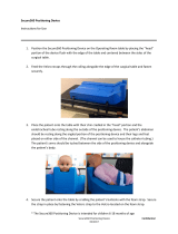
Head Section
The Head Section (1) is inserted into two
sockets located at column end of table
(Refer to “Installing Table Top Sections”).
The Head Section can be placed in infi-
nite positions by depressing handle (2) at
end of Head Section and manually raising
or lowering Head Section. Releasing
handle (2) locks Head Section (1) in de-
sired position. Two gas spring cylinders
on each side of Head Section assist in
raising and lowering it.
Installing Table Top Sec-
tions
The latch handles, located on both sides of table top at column end, can be
placed in three positions:
Unlatched Position (1)
This position allows insertion or removal of a ta-
ble section. Pull outward on latch handle, rotate
handle until it stops, and insert or remove the ta-
ble section.
Auto Capture or Latched Position (2)
Rotate the latch handle until it latches the table
section in position. Pull outward on the table
section to assure it is latched in position.
Locked Position (3)
Rotate the latch handle to lock it tightly in place.
CA800500
1
2
CA800400
Operation

14
RETURN TO TABLE
OF CONTENTS
Possible Pinch Points
Below are listed possible pinch point locations that the operator(s) must be
aware of when setting up and using the table. The possible pinch point loca-
tions are identified by exclamation points
( ! )
on the the table.
1. I.A. Board (73004),
Leg Transfer Board
(73002), or Split Leg
(71111) and base.
2. I.A. Board (73004),
Leg Transfer Board
(73002), or Split Leg
(71111) and floor.
3. Right Side Column.
WARNING
Pinch point locations are identified by an exclamation point
symbol at the specific area of the table. Certain movements
of the table top can result in collision with the floor or base. Use cau-
tion when positioning the table top to prevent injury to patient and oper-
ating room staff or table damage.
OMI 7300
CA801300
OMI 7300
CA801400
CA801500
Operation

15
RETURN TO TABLE
OF CONTENTS
4. Left Side Column
5. Above Pelvic Base (73001)
and Back Section.
6. Below Pelvic Base (73001)
and Back Section.
NOTE
Should other ac-
cessories be in-
stalled instead of
the Pelvic Base
(73001) the possi-
ble pinch point lo-
cations would be
in the same area.
CA801600
OMI 7300
CA801700
OMI 7300
CA801800
Operation

16
RETURN TO TABLE
OF CONTENTS
Pendant Hand Control
Function Buttons
• The pendant hand control consist of 16
buttons. For an explanation of the
operation or function of each button
refer to the Controls & Indicators sec-
tion.
Installation
• Plug the cord of the Hand Control into
the port labeled HAND CONTROL
located on the bottom, patient’s right
side of the table top
Priority
• The Hand Control has priority over the
Foot Control. Should a function be
activated by the Foot Control a person
can override the Foot Control com-
mand through use of the Hand Control.
Display
• Information on the status of the com-
puter, batteries, table movements, and
operating instructions are shown on
the hand control display.
The display
stays activated for 10 seconds after a
function has been pressed
.
EQUIPMENT ALERT
The Models 7100 and
7300 Hand Controls can-
not be inter-changed between the ta-
bles as they are not compatible to the
programmed electronic functions.
WARNING
Should the table malfunction, immediately remove
your hand from the control button. For emergency
operation of the table refer to Emergency Override Panel.
LEVEL
UNLOCK
ENABLE
LOCK
DISABLE
7100
OMI
CA800600
7100
LEVEL
UNLOCK
ENABLE
LOCK
DISABLE
7100
OMI
HAND CONTROL
FOOT CONTROL
CA799400
Operation

17
RETURN TO TABLE
OF CONTENTS
Power On Switch
• The ENABLE/LOCK button is the main On/Off
power switch. When depressed it will first lock
the table to the floor, then display the table posi-
tion, Normal or Reverse. You have approximately
10 seconds to activate a function or positioning
button before the hand control automatically turns
off.
Disable
• The
DISABLE
button, when depressed, turns off
the positioning buttons on the hand control and
will stop the movement of a function when the
foot control is being used. To re-activate the but-
tons on the hand control you must first depress
the
ENABLE/LOCK
button and then the desired function button
Table Position
• You must choose how you want
the table position to be config-
ured by pressing either
Normal
,
(head over column) or
Reverse
,
(head opposite end of column)
Position
. The position activated
will affect certain functions:
1. Flex or Reflex cannot
be activated when in Reverse Position.
2. Trendelenburg, Reverse Trendelenburg, Tilt Left and Tilt Right are automati-
cally configured to operate in conjunction with the Normal and Reverse Posi-
tions. Refer to the Controls & Indicators section.
3. Reverse position is not
available on the Foot or Emergency Override Con-
trols even though the hand control has been configured to operate in the
Reverse Position.
WARNING
It is strongly recommended that the
DISABLE
button be de-
pressed to switch the hand controller OFF
after table posi-
tioning has been completed. This will prevent accidental activation of a
function during procedures.
ENABLE
LOCK
DISABLE
NORMAL
POSITION
REVERSE
POSITION
Operation

18
RETURN TO TABLE
OF CONTENTS
Foot Control
Function Pedals
NOTE
The HAND CONTROL must be
plugged into the table in order for the
foot control to function.
• The foot control has 6 control
pedals; Trendelenburg,
Reverse Trendelenburg, Height
Up, Height Down, Lateral Tilt
Left, and Lateral Tilt Right.
Installation
• Plug the cord of the Foot Con-
trol into the port labeled FOOT
CONTROL located on the bot-
tom, patient’s right side of the
table top
Priority
• The Hand Control has priority
over the Foot Control. Should a
function be activated by the
Foot Control a person can over-
ride the Foot Control command through use of the Hand Control.
Display
• The display on the hand control will display messages when using the Foot
Control.
WARNING
Should the table
malfunction, imme-
diately remove your foot from
the footswitch. For emergency
operation of the table refer to
Emergency Override Panel.
CA800700
OMI
7100
HAND CONTROL
FOOT CONTROL
TRENDEL-
ENBURG
REVERSE
TRENDEL-
ENBURG
TABLE
UP
TABLE
DOWN
LATERAL
TILT
RIGHT
LATERAL
TILT
LEFT
Operation
/