DEVI 140F1137 Operating instructions

Type
Operating instructions

This manual is also suitable for

Installation Guide
DEVIlink™ CC
Central Controller
www.DEVI.com
DEVIlink™ CC
Installation Guide2
Table of Contents
1 Introduction � � � � � � � � � � � � � � � � � � � � � � � � � � � � � � � � � � � � 4
2 Guidelines for installation � � � � � � � � � � � � � � � � � � � � � � � 5
3 Installation plan� � � � � � � � � � � � � � � � � � � � � � � � � � � � � � � � � 6
3.1 Correct installation plan . . . . . . . . . . . . . . . . . . . . . . . . .6
3.2 Incorrect installation plan. . . . . . . . . . . . . . . . . . . . . . . .7
3.3 Repeater units . . . . . . . . . . . . . . . . . . . . . . . . . . . . . . . . . . .8
4 Installation� � � � � � � � � � � � � � � � � � � � � � � � � � � � � � � � � � � � � � 9
4.1 Preparing to add devices. . . . . . . . . . . . . . . . . . . . . . . 11
4.2 Initial settings . . . . . . . . . . . . . . . . . . . . . . . . . . . . . . . . . 12
4.3 Start up the installation menu . . . . . . . . . . . . . . . . . 12
4.4 Creating rooms . . . . . . . . . . . . . . . . . . . . . . . . . . . . . . . . 13
4.5 Adding mains powered devices . . . . . . . . . . . . . . . . 14
4.6 Adding service devices - mains powered . . . . . . . 14
4.7 Adding room devices - mains powered. . . . . . . . . 15
4.8 Adding room devices - battery powered . . . . . . . 17
4.9 Performing network test . . . . . . . . . . . . . . . . . . . . . . . 17
4.10 Finalising the installation . . . . . . . . . . . . . . . . . . . . . . 19
DEVIlink™ CC
3Installation Guide
5 Modifying an existing installation� � � � � � � � � � � � � � � 19
5.1 Adding devices to an existing room . . . . . . . . . . . . 19
5.2 Changing parameters for heat regulations . . . . . 21
5.3 Removing a room or a service device. . . . . . . . . . . 23
5.4 Factory reset of DEVIlink™ CC . . . . . . . . . . . . . . . . . . 24
6 Wi-Fi and App connection� � � � � � � � � � � � � � � � � � � � � � � 24
6.1 Connect to Wi-Fi. . . . . . . . . . . . . . . . . . . . . . . . . . . . . . . 24
6.2 Connect to App. . . . . . . . . . . . . . . . . . . . . . . . . . . . . . . . 25
6.3 Edit connected devices . . . . . . . . . . . . . . . . . . . . . . . . 26
7 Upgrading software version � � � � � � � � � � � � � � � � � � � � 27
8 Warnings� � � � � � � � � � � � � � � � � � � � � � � � � � � � � � � � � � � � � � � 29
8.1 Alert Icons . . . . . . . . . . . . . . . . . . . . . . . . . . . . . . . . . . . . . 30
9 Technical specifications and approvals � � � � � � � � � � 31
10 Radio Equipment Directive � � � � � � � � � � � � � � � � � � � � � 33
11 Warranty� � � � � � � � � � � � � � � � � � � � � � � � � � � � � � � � � � � � � � � 33
12 Disposal instructions � � � � � � � � � � � � � � � � � � � � � � � � � � �34
DEVIlink™ CC
Installation Guide4
1 Introduction
The DEVIlink™ is a programmable,
wireless control system for heating
systems in residential buildings (up
to approximately 300 m
2
).
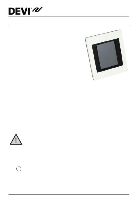
The DEVIlink™ CC is the central
control unit. It has a colour touch
screen from where the entire
installation can be controlled.
This installation guide contains all information about the
DEVIlink™ CC and how to get started.
It guides you through recommendations and considera-
tions that must be taken into account when handling a
wireless system - and it describes the configuration of the
system, to ensure a correct and reliable system set-up.
!
Individual instructions, supplied with the service and
room devices, contain information about connecting
the respective devices to the network. The instruction
will also state whether the device is considered a service device or
a room device.
The
?
key can be used at any point during installation.
Always look for the latest software version at www.DEVI.com
before installation. See "7 Upgrading software version".
DEVIlink™ CC
5Installation Guide
2 Guidelines for installation
The signal strength is sufficient for most applications,
however, wireless signals are weakened on the way from
the DEVIlink™ CC to the room devices and every building
has different obstacles.
Ensure the best performance by keeping the following in
mind for planning and installation:
Max. 30 m between devices in free space.
Receiving devices should be placed on opposite or
next wall as the transmitter, if possible.
All metal objects in the building construction can
weaken wireless signals.
Reinforced concrete walls and floors weaken the
signal strength significantly, but almost any types
of construction materials reduce the signal to some
degree.
Corners that are a result of the building design, can
weaken the wireless signals, due to either long dis-
tances or inadequate reflecting opportunities.
Note! These are guidelines only as many factors have influ-
ence on wireless communication.
DEVIlink™ CC
Installation Guide6
3 Installation plan
DEVI recommends that an installation plan is made
before beginning the actual installation.
1. Create an installation plan of all the room devices
(mains powered and battery powered).
2. Add the DEVIlink™ CC in a central location to the
installation plan.
3. Add necessary repeater units (if any) to the installation
plan. DEVI recommends that you include at least one
repeater unit within 5 meters from the CC.
3�1 Correct installation plan
No metal objects between the DEVIlink™ CC and other
wireless DEVI units.
The DEVIlink™ CC is installed as central as possible on the
floor plan (max. 30 m between devices in free space).
Wireless signal through walls on shortest possible
diagonal distance.
!
RS Sensor
(room device)
DEVIlink™ HC
(service device)
DEVIlink™ CC
living connect
(room device)
living connect
(room device)
DEVIlink™ CC
7Installation Guide
No metal objects between the DEVIlink™ CC and other
wireless DEVI units.
The DEVIlink™ CC is installed as central as possible on the
floor plan (max. 30 m between devices in free space).
Wireless signal through walls on shortest possible
diagonal distance.
RS Sensor
(room device)
DEVIlink™ HC
(service device)
DEVIlink™ CC
living connect
(room device)
living connect
(room device)
3�2 Incorrect installation plan
Metal objects between the DEVIlink™ CC and other
wireless DEVI units.
Decentral installation of the DEVIlink™ CC.
Crossing walls diagonally.
!
!
!
RS Sensor
(room device)
DEVIlink™ HC
(service device)
DEVIlink™ CC
living connect
(room device)
living connect
(room device)
DEVIlink™ CC
Installation Guide8
3�3 Repeater units
A repeater unit strengthens the wireless signal when a
satisfying connection can not be established between
the DEVIlink™ CC and other wireless DEVI mains powered
devices.
Repeater units can be ordered on stock code no. 140F1138.
Placing repeater units
Plan view, single floor building
CC - central controller
FT - floor thermostat (room device)
HC - hydronic controller (service device)
RS - room sensor (room device)
RU - repeater unit (service device)
living connect - radiator thermostat (room device)
RS FT
FT
CC
RU
HC
living connect
living connect
FT
RS
RS
RS
DEVIlink™ CC
9Installation Guide
Cross section view - building with more than one floor
4 Installation
DEVIlink™ CC can be installed with either a PSU (in-wall
power supply) or a NSU (net power supply).
CC
RS
RS
RU
FT
FT
!
Do not
install in
bathrooms
Avoid direct sun
light onto the
DEVIlink™ CC
Install in
height of
140 - 170 cm
DEVIlink™ CC
Installation Guide10
Mounting the DEVIlink™ CC with In-Wall PSU
Hold the PSU over the wall box and
mark up the 4 screw holes. Make
sure the top is level.
Drill holes and insert fitting plugs.
Connect the PSU according to the
connection diagram on the back
side.
Mount the PSU with the 4 screws.
Do not connect the DEVIlink™ CC yet!
Mounting the DEVIlink™ CC with NSU
Place the mounting plate on the wall and mark up the
4 screw holes. Make sure the top is level.
Drill holes and insert fitting
plugs.
Fasten the mounting plate
with the 4 screws.
Do not connect the
DEVIlink™ CC yet!
Connect the NSU to a power outlet.
PSU
UP
UP
NSU
DEVIlink™ CC
11Installation Guide
4�1 Preparing to add devices
When adding devices to the DEVIlink™ system, the distance
between the DEVIlink™ CC and the device must not exceed
1.5 m. To accomplish this the DEVIlink™ Battery Supply Unit
(BSU) is offered as an installation tool.
1. Slide off the lid and insert
the batteries.
2. Slide the lid back on and
attach the DEVIlink™ BSU
battery pack onto the back
of the DEVIlink™ CC.
When ready to do the commissioning, turn the switch
located on the DEVIlink™ BSU to the ON position.
The DEVIlink™ CC will now start up. This takes approxi-
mately 30 seconds.
A battery pack (BSU) can be ordered on stock code no.
014G0262.
01
+
-
x 10
1.5 V AA
DEVIlink™ CC
Installation Guide12
4�2 Initial settings
?
Select Language
Scroll down to select
1
?
Select Country
Scroll down to select
2
?
Select date and time
Set date and time
3
4�3 Start up the installation menu
DEVIlink™ CC
13Installation Guide
Remove the front cover of the DEVIlink™ CC by gently
pulling it off, pull near the edges of the cover.
Press the [SETUP] pin for 3 seconds to enter the
service area.
4�4 Creating rooms
DEVI recommends to create all the rooms before adding
devices
.
?
Service Options
Rooms and Devices
1
?
Rooms and Devices
Add New Room
2
?
Edit Room Name
Enter/edit Room Name
3
Tip! A list of common room names is available here
ABC
.
DEVIlink™ CC
Installation Guide14
4�5 Adding mains powered devices
Pair devices to DEVIlink™ CC.
Start with the device closest to the DEVIlink™ CC, and
move outwards.
4�6 Adding service devices - mains powered
!
Always add dedicated repeater units first!
Power-up all service devices and room devices (mains
powered as well as battery powered).
The DEVIlink™ CC supports many different types of service
devices which can function as simple ON/OFF devices for
other electrically equipment as well as repeater units and
controllers for hydronic systems and other sub-systems.
Press the [SETUP] pin for 3 seconds to enter the service area.
1st
2nd
3rd
DEVIlink™ CC
15Installation Guide
?
Service Options
Rooms and Devices
1
?
Rooms and Devices
Add Service Device
2
?
Add Service Device
Begin Registration
3
?
Edit Device Name
Enter / edit Device Name
4
4�7 Adding room devices - mains powered
A room device regulates temperature in the room where it
is installed. All room devices must be configured, according
to the previous installation plan, to ensure the signal path.
Start with the device closest
to the
DEVIlink™
CC and move
outwards.
DEVIlink™ CC
Installation Guide16
?
Configure Room
Room Device
1
?
Room Device
Scroll down to select
2
?
Add Room Device
Begin Registration
3
?
Room Device
The configuration is valid
4
Press
Note! ON / OFF relays are only visible in the end-user menu.
Note! DEVIlink™ CC automatically selects the regulation
principle according to the types of devices in the room. To
change regulation principle, see "5.2 Changing parameters for
heat regulations"
DEVIlink™ CC
17Installation Guide
4�8 Adding room devices - battery powered
Add the battery powered room devices room by room.
4�9 Performing network test
After finishing the installation perform a network test to
ensure that communication between all added devices and
the DEVIlink™ CC is stable.
Note! Do not perform the network test before the
DEVIlink™ CC is mounted in its final position and connected.
Ensure that all living connects (if any) are out of mounting
mode, see specific instructions following the living connect.
1. Turn off the battery pack.
2. Slide the DEVIlink™ CC onto
the previously installed
mounting plate.
3. The DEVIlink™ CC will now
power-up.
4. Remove the front cover and press the [SETUP] pin for
3 seconds to enter the service area.
If there is uncertainty about the network performance, it is
recommended to perform a network test before the instal-
lation is completed entirely.
DEVIlink™ CC
Installation Guide18
?
Service Options
Status and Diagnostics
1
?
Status and Diagnostics
Network
2
?
Wireless Network Status
Start Network Test
3
At the end of the network test the DEVIlink™ CC waits for all
battery operated devices to wake up and report. Follow the
instructions given on screen.
If the network test is running correctly, there will be no
need for further interaction.
If the network test is performing slow, the DEVIlink™ CC
guides you through troubleshooting and provides useful
tips for speeding up the process.
DEVIlink™ CC
19Installation Guide
4�10 Finalising the installation
Press the [SETUP] pin to close the installa tion.
?
10:15
1
5 Modifying an existing installation
5�1 Adding devices to an existing room
Remove the front cover and press the [SETUP] pin for 3
seconds to enter the service area.
?
Service Options
Rooms and Devices
1
?
Rooms and Devices
Manage Existing Room
2
DEVIlink™ CC
Installation Guide20
?
Manage Existing Room
Configure Existing Room
3
?
Select Room
Choose room
4
?
Configure Room
Room devices
5
?
Room Devices
Add a device
6
?
Add Room Device
Begin Registration
7
Continue until all new devices are added to the desired room.
!
Perform a network test after modifying the installation.
  • Page 1 1
  • Page 2 2
  • Page 3 3
  • Page 4 4
  • Page 5 5
  • Page 6 6
  • Page 7 7
  • Page 8 8
  • Page 9 9
  • Page 10 10
  • Page 11 11
  • Page 12 12
  • Page 13 13
  • Page 14 14
  • Page 15 15
  • Page 16 16
  • Page 17 17
  • Page 18 18
  • Page 19 19
  • Page 20 20
  • Page 21 21
  • Page 22 22
  • Page 23 23
  • Page 24 24
  • Page 25 25
  • Page 26 26
  • Page 27 27
  • Page 28 28
  • Page 29 29
  • Page 30 30
  • Page 31 31
  • Page 32 32
  • Page 33 33
  • Page 34 34
  • Page 35 35
  • Page 36 36

DEVI 140F1137 Operating instructions

Type
Operating instructions
This manual is also suitable for

Ask a question and I''ll find the answer in the document

Finding information in a document is now easier with AI