Page is loading ...

OWNER’S MANUAL
How to install, operate and maintain your
EcoWater Systems
Air Aspirated Iron Filter
Models
ETF2300AIV10
ETF2300AIV12
ETF2300EIV10
ETF2300EIV12
7355286 (Rev. F 8/31/18)
EcoWater Systems LLC
P.O. Box 64420, St. Paul, MN 55164-0420
www.ecowater.com
Designed, Engineered &
Assembled in the U.S.A.
ETF2300AIV10 and ETF2300AIV12 are tested and
certified by the Water Quality Association against
NSF/ANSI Standard 372 for low lead content.
ETF2300EIV10 and ETF2300EIV12 are tested and
certified without media by the Water Quality
Association against CSA B483.1, NSF/ANSI 61,
and NSF/ANSI Standard 372 for low lead content.

2
This system is not intended to be used for treating water
that is microbiologically unsafe or of unknown quality
without adequate disinfection before or after the system.
FCC NOTICE
NOTE: This equipment has been tested and found to
comply with the limits for a Class B digital device, pur-
suant to Part 15 of the FCC Rules. These limits are
designed to provide reasonable protection against
harmful interference in a residential installation. This
equipment generates, uses, and can radiate radio fre-
quency energy and, if not installed and used in accor-
dance with the instructions may cause harmful interfer-
ence to radio communications. However, there is no
guarantee that interference will not occur in a particular
installation. If this equipment does cause harmful inter-
ference to radio or television reception, which can be
determined by turning the equipment off and on, the
user is encouraged to try to correct the interference by
one or more of the following measures:
= Reorient or relocate the receiving antenna.
= Increase the separation between the equipment and
receiver.
= Connect the equipment into an outlet on a circuit dif-
ferent from that to which the receiver is connected.
= Consult the dealer or an experienced radio/TV tech-
nician for help.
Changes or modifications not expressly approved by
EcoWater Systems could void the user’s authority to
operate the equipment.
This device complies with Industry Canada Standard
RSS-210. Operation is subject to the following two con-
ditions: (1) this device may not cause interference, and
(2) this device must accept any interference, including
interference that may cause undesired operation of the
device.
Ce dispositif est conforme avec la norme CNR-210
d’Industrie Canada. Le fonctionnement du dispositif
est sujet aux deux conditions suivantes: (1) le dispositif
ne doit pas causer de brouillage, et (2) le dispositif doit
accepter tous brouillages, incluant tous brouillages qui
peut nuire au bon fonctionnement du dispositif.
European Directive 2002/96/EC requires all
electrical and electronic equipment to be dis-
posed of according to Waste Electrical and
Electronic Equipment (WEEE) requirements.
This directive or similar laws are in place
nationally and can vary from region to region.
Please refer to your state and local laws for
proper disposal of the equipment.
SAFETY GUIDES
Follow the installation instructions carefully. Failure to
install the water filtration system properly voids the
warranty.
Before you begin installation, read this entire manual.
Then, obtain all the materials and tools you will need to
make the installation.
Check local plumbing and electrical codes. The
installation must conform to them.
Use only lead-free solder and flux for all sweat-solder
connections, as required by state and federal codes.
Use care when handling the water filtration system. Do
not turn upside down, drop, or set on sharp protrusions.
Do not locate the water filtration system where freezing
temperatures occur. Do not attempt to treat water over
120°F. Freezing, or hot water damage voids the
warranty.
The water filtration system requires a minimum water
pressure of 30 psi at the inlet. Maximum allowable
inlet water pressure is 125 psi. If daytime pressure is
over 80 psi, nighttime pressure may exceed the maxi-
mum. Use a pressure reducing valve if necessary
(Adding a pressure reducing valve may reduce the flow).
The water filtration system works on 24V DC electrical
power, supplied by a direct plug-in power supply
(included). Be sure to use the included power supply,
and plug it into a nominal 120V, 60 Hz household outlet
that is in a dry location only, grounded and properly
protected by an overcurrent device such as circuit
breaker or fuse.
TABLE OF CONTENTS Page
S
pecifications & Dimensions . . . . . . . . . . . . . . . . . . . 3
Before Starting Installation . . . . . . . . . . . . . . . . . . . . 4
Media Loading (EIV Models) . . . . . . . . . . . . . . . . . . . 5
Typical Installation Illustrations . . . . . . . . . . . . . . . . . 6
Installation . . . . . . . . . . . . . . . . . . . . . . . . . . . . . . . 7-8
Description of Operation . . . . . . . . . . . . . . . . . . . . . . 9
Sanitizing Procedure . . . . . . . . . . . . . . . . . . . . . . . . . 9
Setup Procedure . . . . . . . . . . . . . . . . . . . . . . . . 10-13
Filter Operation . . . . . . . . . . . . . . . . . . . . . . . . . . 14-25
Service Information . . . . . . . . . . . . . . . . . . . . . . 26-31
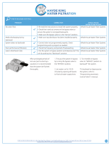
Troubleshooting Guide . . . . . . . . . . . . . . . . . . . . . . 28
Wiring Schematic . . . . . . . . . . . . . . . . . . . . . . . . . . . 31
Repair Parts . . . . . . . . . . . . . . . . . . . . . . . . . . . . 33-35
Warranty . . . . . . . . . . . . . . . . . . . . . . . . . . . . . . . . . 36
ECOWATER
S Y S T E M S
Table of Contents & Safety Guides

3
SPECIFICATIONS
Model ETF2300AIV10 ETF2300AIV12 ETF2300EIV10 ETF2300EIV12
Model Code HAIV0 HAIV2 HEIV0 HEIV2
Amount of Zeolite Media 1.0 cu. ft. 2.0 cu. ft. ––
Amount of Quartz Gravel 17 lbs. 29 lbs. 17 lbs. 29 lbs.
Flow Rate 7-10 gpm 9-15 gpm 7-10 gpm 9-15 gpm
Minimum Backwash Flow Rate 7 gpm* 10 gpm* 7 gpm*** 10 gpm***
Maximum Supply Water Pressure 80 psi
Water Temperature Limits (min./max.) 40 - 120 °F (4 - 49 °C)
Contaminant Removal Limitations
Up to 10 ppm iron (except bacterial
and organically bound iron**)
Consult media specifications for
contaminant limitations
*Well pump must be able to provide the
minimum flow for 30+ minutes.
**Consult manufacturer for applications
with bacterial or organically bound iron.
***Install a backwash flow control that is
appropriately sized for the media used.
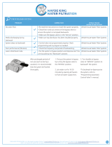
A
FRONT VIEW
SIDE VIEW
TOP VIEW
14-1/4"
13-5/8"
IN
3-3/4"
OUT
IN - OUT
B
ECOWATER
S Y S T E M S
Specifications & Dimensions
14-1/4”
SIDE VIEW FRONT VIEW
TOP VIEW
13-5/8”
3-3/4”
IN
OUT
IN - OUT
A
B
DIMENSIONS
Model
Nominal
Mineral Tank
Size
Dimension
A
Dimension
B
ETF2300AIV10
ETF2300EIV10
10” Dia. x 47” 57” 50”
ETF2300AIV12
ETF2300EIV12
12” Dia. x 54” 62-1/4” 55-1/4”
FIG. 1

4
ECOWATER
S Y S T E M S
Before Starting Installation
PLAN HOW YOU WILL INSTALL THE FILTER
You must first decide how to run in and out pipes to
the filter. Look at the house main water pipe at the
point where you will connect the filter. Is the pipe sol-
dered copper, glued plastic, or threaded brass/galva-
nized? What is the pipe size?
Now look at the typical installation illustration on page
6. Use it as a guide when planning your particular
installation. Be sure to direct incoming, unfiltered
water to the filter valve inlet fitting. The valve ports
are marked IN and OUT.
UNPACKING
EcoWater Systems Air Aspirated Iron Filters are
shipped from the factory in one master carton. The
carton also includes a bag of small parts needed to
assemble and install the unit, plus this manual.
N
OTE: Filtering mineral is not included with mod-
els ETF2300EIV10 & EIV2300EIV12.
Thoroughly check the filter for possible shipping dam-
age and parts loss. Also inspect and note any dam-
age to the shipping carton. Notify the transportation
company if damage is present. EcoWater Systems is
not responsible for in-transit damages.
Remove and discard (RECYCLE) all packing materi-
als. We suggest you keep the small parts in the
bag(s) until you are ready to use them.
WHERE TO INSTALL THE FILTER
= Place the filter as close as possible to the pressure
tank (well system) or water meter (city water).
= Place the filter as close as possible to a floor
drain, or other acceptable drain point (laundry tub,
sump, standpipe, etc.). CAUTION: Drain water
exits the hose at a fast flow rate, and at water sys-
tem pressure. Be sure the hose is fastened in
some manner to prevent ”whipping” and splashing
to prevent water damage to surrounding area.
= Connect the filter to the main water supply pipe
UPSTREAM OF the water heater. DO NOT RUN
HOT WATER THROUGH THE FILTER. The tem-
perature of water passing through the filter must
be less than 120°F.
= Keep outside faucets on unfiltered water to con-
serve filtering capacity.
= Do not install the filter in a place where it could
freeze. Damage caused by freezing is not cov-
ered by the warranty.
= Put the filter in a place water damage is least likely
to occur if a leak develops. The manufacturer will
not repair or pay for water damage.
= A 120V, 60 Hz electrical outlet, to plug the included
power supply into, is needed near the filter. Be
sure the electrical outlet and power supply are in
an inside location, to protect from wet weather.
= If installing in an outside location, you must take the
s
teps necessary to assure the filter, installation
plumbing, wiring, etc., are as well protected from the
elements, contamination, vandalism, etc., as when
installed indoors.
= A drain is needed for recharge discharge water. A
floor drain is preferred, close to the filter. A laundry
tub, standpipe, etc., are other options. Be sure to
provide a 1-1/2" minimum air gap, to prevent possi-
ble sewer water backup.
TOOLS, PIPE & FITTINGS,
OTHER MATERIALS YOU WILL NEED
= Plastic inlet and outlet fittings included with the filter
allow water flow equivalent to 1 inch nominal pipe.
To maintain full valve flow, 1” pipes to and from the
filter fittings are recommended. Do not reduce the
pipes to less than 3/4” size.
= Use copper, brass or PEX plastic pipe and fittings.
= ALWAYS install the included bypass valve, or 3 shut-
off valves. Bypass valves let you turn off water to
the filter for repairs if needed, but still have water
available to the house pipes.
= Drain hose 5/8” inside diameter minimum, with a
garden hose connection on one end, is needed for
the valve drain. See step 5 on page 8.
= If a rigid valve drain is needed, to comply with plumb-
ing codes, you can buy the parts needed (see page
6) to connect a 5/8” minimum copper tubing drain.
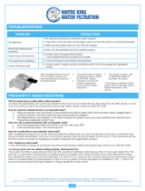
OR
City Water Supply
Well Water Supply
Well
Pump
Pressure
Tank
Untreated Water to
Outside Faucets
Water
Heater
Water
Softener
Taste
& Odor
Filter
Iron
Filter
Sediment
Filter
Neutral -
izer
Filter
Cold Water
to House
Hot Water
to House
FIG. 2
NOTE: Not all devices shown would be needed on a typical water supply.
Illustration shows proper relative sequence for installation.

5
ECOWATER
S Y S T E M S
Media Loading (Models ETF2300EIV10 & ETF2300EIV12)
MEDIA LOADING
M
odels ETF2300EIV10 & ETF2300EIV12, as manu-
factured, have no media other than quartz gravel at
the bottom of the tank (See table on Page 3 for
amounts). Before plumbing these units, load media:
1. Move the filter into installation location and set it on
a flat, level surface. If a twin installation, keep
tanks separated for ease of service.
2. Take off the unit’s top cover and unplug the wiring
connections between the valve and the control
board (PWA).
3. Remove retainer clips and clamp sections from the
tank neck and carefully lift the valve off the tank.
4. Check the height of the riser pipe as shown in
Figure 3. If riser pipe is more than 1/2” above the
top distributor, make sure that bottom distributor is
below gravel at the bottom of the tank. It may be
necessary to lay the filter on its side to move gravel
to one side, hold the bottom distributor at the bot-
tom center of the tank and stand the unit back up.
Level gravel after checking.
5. After confirming the riser pipe height, remove the
top distributor from the tank neck, leaving the bot-
tom distributor (including riser pipe) in place, cen-
tered in the tank.
6. Cover the top end of the riser pipe with a clean
rag, to keep media out (See Fig. 4).
7. Using a larger neck funnel, add the necessary
amount of media.
8. Flush the tank opening with water to clean media
particles from the top of the tank. Uncover the bot-
tom distributor stand tube.
9. Fill the tank with water, up to the top of the tank.
IMPORTANT: Be sure to fill with water. This will elim-
inate air space, wet the media and pre-
vent excessive air-head pressure when
filter is pressurized.
10. Install the o-ring seals and top distributor exactly
as shown in Figure 5. Place the small o-ring at
the top of the riser pipe, where shown in Figure 3.
If the o-rings need lubrication, use a high quality
silicone grease.
11. Lower the valve assembly onto the tank, centering
over the riser tube. Push downward, against the
o-ring, and install the clamp sections, securing
with the retainer clips.
12. Reconnect the wiring between the valve and the
control board (PWA).
13. Verify that the drain flow plug (See Key No. 59 on
Page 35) is appropriately sized for the media
used. If necessary, install a different flow plug.
FIG. 5
Top
Distributor
Bottom
Distributor
Riser Pipe
O-Ring, 2-7/8” x 3-1/4”
Make sure o-ring
sealing surfaces
are clean
O-Ring, 13/16” x 1-1/16”
O-Ring, 2-3/4” x 3”
Top Edge of
Top Distributor
Riser Pipe
0” to 1/2”
Note: Resin tank height can vary somewhat within manu-
facturing tolerance. So that the bottom distributor riser pipe
has proper clearance with inside valve porting, check for
the correct length, as shown above. Cut the riser pipe if
needed to adjust the length. Be sure to remove burrs and
sharp edges.
FIG. 3
FIG. 4
Funnel
Plug or cover top of
riser pipe
Tank
Make sure
bottom distributor
is centered

ECOWATER
S Y S T E M S
Typical Installation Illustrations
6
FIG. 8
Drain
Fitting
Valve
Drain
Hose
5/8” I.D.
(minimum)
copper tube
Push in for
Bypass
Clip
Drain Fitting
CONNECTING A RIGID VALVE DRAIN TUBE
To adapt a copper tube to the filter, buy a compression fitting (garden hose thread to
5/8” I.D. minimum tube and necessary tubing from your local hardware store.
Adaptor, garden hose
thread to compression
Pull out for
filtered water
“Service”
FIG. 7FIG. 6
INSTALLATION USING 3-VALVE BYPASS
M
A
IN
WAT
E
R
PIPE
M
A
IN
WAT
E
R
P
IP
E
INSTALLATION USING ECOWATER BYPASS VALVE
CROSS-OVER
Use if water supply flows from the left.
Include single or 3-valve bypass.
Filtered
Water OUT
Unfiltered
Water IN
F
ILTERED
WATER
T
O FILTER
I
NLET
UNFILTERED
WATER
F
ROM FILTER
O
UTLET
BYPASS
Valve
O
UTLET
Valve
INLET
Valve
O-Ring Seal (2)*
Valve
INLET
For filtered water SERVICE:
-Open the inlet and outlet
valves
For unfiltered BYPASS:
-Close the inlet and outlet
valves
-Open the bypass valve
Unfiltered Water
to Outside Faucets
* Included with filter - Pipe and
fittings supplied by installer.
1” Copper Tube (2)*
#7214383
Bypass
Valve
Clip (2)*
O-Ring Seal (2)*
1” Sweat Adaptor (2)
not included
Valve
INLET
1” Sweat
Adaptor (2)
not included
1” Copper Tube (2)*
120V,
60 Hz
Outlet
Clip (2)*
Valve Drain Hose
(do not elevate
more than 8 ft.)
to drain - provide a 1-1/2” minimum
air gap. Secure the valve drain hose
in place to keep over drain.

7
1. TURN OFF WATER SUPPLY
a
. Close the main water supply valve near the well
pump or water meter.
b. Shut off the electric or fuel supply to the water
heater.
c. Open high and low faucets to drain all water from
the house pipes.
2. INSTALL BYPASS VALVE AND/OR
PLASTIC ADAPTOR / COPPER TUBE:
a. If installing a single bypass valve, push the bypass
valve, with lubricated o-ring seals in place, into the
valve inlet and outlet ports (See Figures 6 & 9).
- OR -
b. If installing a 3-valve bypass system, slide plastic
installation adaptor and copper tube, with lubricat-
ed o-ring seals in place, into the valve inlet and
outlet ports, respectively (See Figures 7 & 9).
c. Make sure that the check valve is in place in the
valve inlet, with the flow arrow pointed inward, as
shown in Figure 9.
d. Make sure that the turbine and support are in place
in the valve outlet, as shown in Figure 10.
e. Snap the two large plastic clips in place on the inlet
and outlet ports, from the top, down (See Figure
11). Be sure they snap into place. Pull on the
bypass valve, copper tube or plastic adaptor, to
make sure they are held securely in place.
3. COMPLETE PLUMBING TO AND FROM
THE FILTER
Using the “Typical Installation Illustrations” on page 6
as a guide, observe all of the following cautions while
you connect inlet and outlet plumbing:
= Be sure incoming, unfiltered water is directed to
the valve INLET port.
= Be sure to install bypass valve(s).
= If making a soldered copper installation, do all
sweat soldering before connecting pipes to the fil-
ter fittings. Torch heat will damage plastic parts.
= Use pipe joint compound on all external pipe
threads.
= When turning threaded pipe fittings onto plastic fit-
tings, use care not to cross-thread.
= Support inlet and outlet plumbing in some manner
(use pipe hangers) to keep the weight off of the
valve fittings.
Turbine
Support
Valve
Outlet
FIG. 10
FIG. 11
O-ring
Clip
Cross section of
valve inlet or outlet
Bypass valve,
copper tube or
plastic adaptor
Snap clips into place between
larger diameter rings
FIG. 12
Turn the bypass
valve downward if
connecting to floor
level plumbing
INLET
OUTLET
FIG. 9
INLET
OUTLET
Clip (2)
Bypass Valve
Clip (2)
T
urbine
1” Copper Tube
(install in filter valve
or bypass valve)
ECOWATER
S Y S T E M S
Installation
Check Valve
(note direction
of flow arrow)
Turbine
Support

8
ECOWATER
S Y S T E M S
Installation
b. Place bypass valve(s) into “bypass” position. On a
single valve, slide the stem inward to BYPASS
(See Fig. 8 on page 6). On a 3 valve system,
close the inlet and outlet valves, and open the
bypass valve (See Fig. 7 on page 6).
c. Fully open the house main water pipe shutoff valve.
Observe a steady flow from both opened faucets.
d. Close both faucets.
e. Check your plumbing work for leaks and, if any are
found, fix right away. Be sure to observe previous
caution notes.
f. Turn on the gas or electric supply to the water
heater. Light the pilot, if applicable.
7. CONNECT TO ELECTRICAL POWER:
The filter controller works on 24V DC electrical power.
The included power supply converts 120V AC house-
hold power to 24V DC. Plug the power supply into a
120V, 60 Hz electrical outlet. Be sure the outlet is
always “live” so it can not be switched off by mistake.
8. PROGRAM THE CONTROLLER
See pages 10-12 for instructions to program the elec-
tronic controller.
9. START UP PROCEDURE
a. Confirm that the filter’s main valve is in the “service”
position (“S” on the cam).
b. Place bypass valve(s) into “service”, EXACTLY as
follows:
= Single Bypass Valve: SLOWLY, pull the valve
stem outward to ”service” position, pausing sev-
eral times to allow the filter to pressurize slowly.
= 3 Valve Bypass: Fully close the bypass valve
and open the outlet valve. SLOWLY, open the
inlet valve, pausing several times to allow the
filter to pressurize slowly.
c. Check all connections for leaks.
d. Start a recharge: From the rolling status screens,
press the SELECT (¡) button to display the Main
menu. Make sure Recharge is highlighted, then
press SELECT (¡). Press DOWN (6) to scroll to
Recharge now, then press SELECT (¡) twice.
You should hear the valve motor run as the filter
begins recharging. Verify that the valve advances
to “backwash” (BW) position.
e. Allow the unit to remain in “backwash” (BW) while
air is purged and water exits the drain line. Ensure
that the drain line is secure and will withstand the
mix of air and water exiting.
f. Allow the unit to complete the 15 minute “backwash”
cycle and automatically advance to the “aspirate” (A)
position. Allow it to remain there as it aspirates air
into the mineral tank. After 75 minutes, the filter will
then automatically return to “service”. Start up is
complete.
4. COLD WATER PIPE GROUNDING
The house cold water pipe (metal only) is often used
as a ground for the house electrical system. The 3-
valve bypass type of installation, shown in Figure 7,
will maintain ground continuity. If you use the plastic
bypass, continuity is broken. To restore the ground,
do either step 4a or 4b following.
a. Use the EcoWater ground clamp kit (not included)
to make a jumper across the inlet and outlet pipes
(See Figure 13).
b. Install a #4 copper wire across the removed sec-
tion of main water pipe, securely clamping at both
ends – parts not included.
5. INSTALL VALVE DRAIN HOSE
a. Take a length of 5/8” inside diameter garden hose
and attach to the valve drain fitting (See Figure 8
on page 6).
b. Locate the other end of the hose at a suitable drain
point (floor drain, sump, laundry tub, etc.). Check
and comply with local codes. Refer to Figure 8 on
page 6 if codes require a rigid pipe drain run.
IMPORTANT: Use high quality, thick wall hose that
will not easily kink or collapse. The fil-
ter will not backwash properly if water
cannot exit this hose during recharges.
c. Tie or wire the hose in place at the drain point.
Water pressure will cause it to whip during the
backwash portion of the recharge cycle. Also pro-
vide an air gap of at least 1-1/2” between the end
of the hose and the drain point. An air gap pre-
vents possible siphoning of sewer water, into the
filter, if the sewer should back up.
d. If raising the drain hose overhead is required to get
to the drain point, do not raise higher than 8 feet
above the floor. Elevating the hose may cause a
back pressure that could reduce backwash flow
and proper mineral bed cleaning.
6. FLUSH PIPES AND TEST FOR LEAKS
CAUTION: To avoid water or air pressure damage to
filter inner parts, be sure to do the follow-
ing steps exactly as listed:
a. Fully open two filtered water faucets, one cold and
one hot, nearby the filter.
FIG. 13
Ground
Clamp
Inlet / Outlet
Pipes

9
ECOWATER
S Y S T E M S
Description of Operation
Service water enters the filter and passes through air
captured at the top of the mineral tank. Dissolved iron
is oxidized and then removed by the media in the
t
ank. When the system recharges, it first backwash-
es the contaminants to the drain, then empties the
tank of water, replacing it with air drawn through the
aspirator. When the system returns to "service", the
water pressure will compress the air in the mineral
t
ank and leave an 8-14" head of air on the top of the
tank.
Care is taken at the factory to keep your water filter
clean and sanitary. Materials used to make the filter
will not infect or contaminate your water supply, and
will not cause bacteria to form or grow. However,
during shipping, storage, installing and operating,
bacteria could get into the filter or media. For this
reason, sanitizing as follows is suggested* when
installing.
1. Obtain pharmaceutical grade 12% hydrogen perox-
ide solution. One quart (0.95 L) is required for a
10" filter, 2 quarts (1.9 L) for a 12" filter.
2. Remove air inlet screen from check valve on the
valve’s nozzle & venturi assembly (See Figure 14).
3. Connect a length of 3/8 I.D. tubing to the barb on
the aspirator check valve (See Figure 15).
4. Insert the free end of the tubing into the hydrogen
peroxide container.
5. Start a recharge: From the rolling status screens,
press the SELECT (¡) button to display the Main
menu. Make sure Recharge is highlighted, then
press SELECT (¡). Press DOWN (6) to scroll to
Recharge now, then press SELECT (¡) twice.
You should hear the valve motor run as the filter
begins recharging. The filter will backwash for 15-
17 minutes, then advance automatically to the
“aspirate” position. It will draw the hydrogen perox-
ide into the filter and pass it through the zeolite
media, cleaning and sanitizing the media.
6. Allow the filter to draw air for the remainder of the
time in the “aspirate” cycle after the hydrogen per-
oxide has been drawn into the filter.
7. The filter will return to “service” automatically when
the “aspirate” cycle is complete.
8. Remove tubing and reinstall the aspirator inlet
screen onto the barbed fitting on aspirator check
valve.
9. Cleaning/sanitizing process is complete.
*NOTE:
Sanitizing is recommended by the Water Quality
Association for disinfecting. On some water sup-
plies, they suggest periodic sanitizing.
FIG. 14
FIG. 15
Valve nozzle &
venturi assembly
Valve nozzle &
venturi assembly
Place other end of tube in
hydrogen peroxide solution
Check valve
3/8” barb
Remove air
inlet screen
Check valve
3/8” barb
Connect 3/8” I.D.
tubing to barb
ECOWATER
S Y S T E M S
Sanitizing Procedure

10
SETUP PROCEDURE
When the EcoWater Systems filter is plugged in for the
first time, a beep sounds and the display briefly shows
a logo, followed by model information. Next, a series of
“wizard” screens prompts you to enter basic operating
information:
FIG. 17
1. LANGUAGE If the desired language already has a
dot next to it (See Figure 17), go to Step 2.
Otherwise, press the filter’s DOWN (6) or UP (5)
buttons to scroll to the desired language, then press
the SELECT (¡) button to choose it.
2. Press the SELECT (¡) button to advance to the next
“wizard” screen.
Pushbutton (WPS)
Browser
Skip
Wireless setup
FIG. 18
NOTE: Wireless Setup can also be done after the rest
of the Setup Procedure (Steps 16-24) has been
completed. From the Main menu, go down to
the Advanced settings menu and select
Wireless setup.
3. WIRELESS SETUP Choose how you will connect
the filter to your home’s wireless network:
Browser: You can connect using the browser on your
laptop, tablet or phone. Skip to Step 7.
OR
Pushbutton: If your wireless router has a WPS (Wi-
Fi Protected Setup) or Push to Con -
nect button, you can use this method to
connect. Proceed to Step 4.
English
Español
Français
Language
ECOWATER
S Y S T E M S
Setup Procedure
P
ush wireless router
button
Wireless setup
Cancel
FIG. 19
Connected!
Key:
abc123
Wireless setup
Continue
FIG. 20
Pushbutton (WPS) Option
4. Use the SELECT (¡) button to choose Pushbutton
(
WPS). The filter display will change to show “Push
wireless router button”.
5. Press the WPS or Push to Connect button on your
router and wait for a minute or two to see if the dis-
play changes again to “Connected” and gives you a
key code. If not, you may need to cancel and use
the browser option.
6. Once the key code is displayed, write it down. It will
be used when you register your system on the Eco -
Water web site. Proceed to Step 16 on the next page.
NOTE: If the “Connected” message shows “
------
”
(dashes) instead of a key code, it may be that
your router is not connected to the internet.
Verify that the router’s internet connection works
with your laptop or other device.
Browser Option
7. Press the filter’s DOWN (6) button to scroll to
Browser.
8. Press the SELECT (¡) button twice. The filter dis-
play will change to show “See connection instruc-
tions”.
Pushbutton (WPS)
Browser
Skip
Wireless setup
FIG. 21
See connection
instructions
Wireless setup
Cancel
FIG. 22
continued on the next page
FIG. 16
Display
LEFT
Button
RIGHT
Button
UP
Button
DOWN
Button
SELECT
Button

11
9. On your laptop,
tablet or phone,
activate the view of
wireless networks
in range. For
example, on a lap-
top, look for and
click on the wire-
less icon along the
lower right edge of
the screen. On a
phone, you should
go into “Settings”
and look for “Wi-Fi”.
10. You should see a
network named
“H2O-” followed by
12 characters.
Select this network
to connect your
device with it.
11. Once your device indicates that it is connected to
the H2O network, go to your internet browser
(Chrome, Firefox, Internet Explorer, etc.) and type in
this URL:
192.168.0.1
then click Go or press Enter.
FIG. 23
FIG. 24
12. After a screen like the one shown above appears,
select your in-home wireless network and enter the
correct password.
13. The filter display should change to “Connected” and
give you a key code.
ECOWATER
S Y S T E M S
Setup Procedure
Connected!
Key:
abc123
Wireless setup
Continue
FIG. 25
14. Once the key code is displayed (it may take a few
seconds) , write it down. It will be used when you
register your system on the EcoWater web site.
NOTE: If the “Connected” message shows “
------
”
(dashes) instead of a key code, it may be that
y
our router is not connected to the internet.
Verify that the router’s internet connection works
with your laptop or other device.
15. On your laptop, tablet or phone, go back to the view
of networks in range, and make sure that your
device is connected back to your local network.
Finish Setting up the Filter
16. Once you have connected the Wi-Fi system and
written down your key code, press the SELECT (¡)
button to advance to the next “wizard” screen.
continued from the previous page
English
Metric
System units
FIG. 26
17. SYSTEM UNITS If the desired system already has
a dot next to it (See Figure 26), go to Step 18.
Otherwise, press the DOWN (6) or UP (5) buttons
to scroll to the desired system, then press the
SELECT (¡) button to choose it.
18. Press the SELECT (¡) button.
12:34 PM
Current time
FIG. 27
19. CURRENT TIME Press the DOWN (6) or UP (5)
buttons to set the current time (See Figure 27). Hold
the button down to rapidly advance. Be sure that AM
or PM is correct. If the system units were set to met-
ric in Step 17, the clock will be in 24-hour format.
20. Press the SELECT (¡) button.
21. MAX. DAYS BETWEEN RECHARGES Press the
UP (5) or DOWN (6) buttons to set the number of
days between automatic recharges (See Figure 28)
The feature can be set from 1 to 99 days.
continued on the next page
1 days
Max. days between
recharges
FIG. 28

12
Wireless information
DSN: AC000W000009876
K
ey:
abc123
FIG. 30
Model information
W
ireless information
Daily avg. water used
System information
ECOWATER
S Y S T E M S
Setup Procedure
NOTE: You can look up the current key code on your
filter’s controller. From the Main menu, go
down to the System information menu and
select Wireless information.
28. After you’ve entered the key code in the Add
System screen, click the “Connect” button to
advance to the Customer Information screen.
29. Fill in the customer information (address, e-mail,
etc.). When entering a password, either have the
customer enter their own, or enter one for them and
give it to them. If you intend to share the system,
sharing needs to be done from the customer’s
account (See “How to Share a System” on the fol-
lowing page). When finished filling in the customer
information screen, click the “Save and Continue”
button.
NOTE: When filling in address information, be sure to
select the country before attempting to select a
state or province.
30. Fill in the System Settings screen and click the
“Save Settings” button.
31. Fill in the Dealer Communication Preferences
screen and click the “Save and Continue” button.
32. The message “Customer System Setup Complete”
should appear, along with the customer’s account
screen. At this point you can make changes or add
another system for this customer. When everything
is correct, return to the dealer Home page by click-
ing the “Home” tab along the top of the page.
33. On the dealer Home page, the new system you set
up should appear on the systems list.
NOTE: On the dealer Home page, the number of
shared systems is displayed below the bar
along the top of the screen. You can display
only shared systems by clicking “shared with
you”, and display all systems again by clicking
the “Home” tab. See the following page for
instructions on how to share a system.
NOTE: A dealer registering filters must log in as a
dealer, not as a customer.
25. In your internet browser, type in this URL:
http://wifi.ecowater.com
26. If you are a dealer, and have an account, log in to
your account and go to the next step. If you are a
customer, go to Page 13 for instructions to create
an account and register.
27. After you’ve logged in to your dealer account, click
“Add New Customer System” and then enter the
key code that you wrote down earlier. If you wait
Run system
Redo setup
Setup complete!
FIG. 29
23. If, at this point, you want to go back and make
changes, press the DOWN (6) button to scroll to
Redo setup, then press the SELECT (¡) button
twice to repeat the “wizard” screens.
24. If no changes are desired, make sure Run system
has a dot next to it (See Figure 29) and press the
SELECT (¡) button. The unit begins normal opera-
tion, described on Page 14.
HOW TO REGISTER A SYSTEM ON THE
ECO WATER WEB SITE AS A DEALER
continued from the previous page
Use the table above to determine the number of days
between recharges, based on the number of people
in the household and the iron ppm (parts per million)
in the water supply.
NOTE: If the water supply has high turbidity (sand, silt,
sediments, etc.) set to recharge more often than
the table shows.
22. Press the SELECT (¡) button. The screen will
show “Setup complete!” (See Figure 29).
No. of
People
Iron (parts per million)
1 - 2 3 - 5 6 - 10 11 - 20
1 - 2 3 days 2 days 1 day
use AIV12
3 - 4 2 days 2 days 1 day
use AIV12
5 - 7 1 day 1 day
use AIV12 use AIV12
Model
ETF2300-
AIV10
Model
ETF2300-
AIV12
1 - 2 4 days 3 days 2 days 1 day
3 - 4 3 days 2 days 1 day 1 day
5 - 7 2 days 1 day 1 day 1 day
too long between writing down the key code and
registering (an hour or less), the code may change.
This is a security feature. Look up the new key
c
ode, as described in the following note.

13
ECOWATER
S Y S T E M S
Setup Procedure
HOW TO CREATE AN ACCOUNT AND REG-
ISTER YOUR SYSTEM ON THE ECO WATER
WEB SITE AS A CUSTOMER
NOTE: A dealer registering filters must log in as a
dealer, not as a customer.
1. In your internet browser, type in this URL:
http://wifi.ecowater.com
2. If you are a new customer, click on “Create Account”
to advance to the Create Your Account screen.
3. Fill in the account information (e-mail, password, lan-
guage, etc.). Agree to the Terms of Use, and then
click the “Create Account” button to advance to the
Customer Information screen.
4. Fill in the customer information (name, address, etc.).
When finished filling in the customer information
screen, click the “Save and Continue” button.
NOTE: When filling in address information, be sure to
select the country before attempting to select a
state or province.
5. Follow the instructions on the Verify e-mail screen.
You will shortly receive an e-mail confirming that you
have created your account. Open this e-mail and
click on the link it contains. Your browser will be
directed to a Verification Complete screen.
6. Now that you have created your account, you may
log in. In the verification screen, click the “logging in”
link (or go to http://wifi.ecowater.com).
7. Log in with the e-mail and password that you entered
when creating your account.
8. After you’ve created and logged in to your account,
the Add System screen will appear. Enter the key
code that you wrote down earlier. If you wait too
long between writing down the key code and register-
ing (an hour or less), the code may change. This is
a security feature. Look up the new key code, as
described in the following note.
Wireless information
DSN: AC000W000009876
Key:
abc123
FIG. 31
Model information
Wireless information
Daily avg. water used
System information
9. After you’ve entered the key code in the Add System
screen, click the “Connect” button to advance to the
System Settings screen.
10. Fill in the System Settings screen and click the
“
Save Settings” button.
11. Fill in the Communication Preferences screen and
click the “Save and Continue” button.
12. The screen should change to show the Home page
for your system, including the filter “dashboard”.
Click the “Log Out” tab when you are done.
VISITING YOUR CUSTOMER ACCOUNT
Any time after your customer account has been created
and system registered, you can visit your account to
see your filter “dashboard”, change settings, etc. Direct
your browser to http://wifi.ecowater.com and log in
using the e-mail and password that were specified
when setting up the account.
HOW TO SHARE A SYSTEM BETWEEN A
DEALER AND CUSTOMER
NOTE: You can look up the current key code on your
filter’s controller. From the Main menu, go
down to the System information menu and
select Wireless information.
Systems can be “shared” between a dealer and cus-
tomer. If a system is shared, the dealer has full access
to the displays and settings for that system on the
EcoWater Wi-Fi web site. If a system is not shared, the
dealer only has access to the “Dealer Communication
Preferences” screen for that system.
Once a customer account has been created by a deal-
er, a customer can grant a dealer access to their sys-
tem. Access can only be granted to the dealer who
sold that system.
With permission, a dealer (but only the one who sold
the system) could also grant it for the customer. To do
so, a dealer must log in as a customer rather than as a
dealer, using the customer’s e-mail and password
(which were entered when the customer account was
created).
1. Go to http://wifi.ecowater.com and log in (cus-
tomer’s e-mail and password, not dealer’s).
2. Click on the “Support” tab along the top of the cus-
tomer Home page.
3. On the Support screen, click the “Grant Access” but-
ton. It should change to read “Revoke Access”.
4. The system is now shared. Click the “Log Out” tab
when you are done.
NOTE: A system can only be shared from a cus-
tomer’s account, not a dealer’s.

14
NORMAL OPERATION
FILTER STATUS SCREENS
During normal operation, the EcoWater Systems filter’s
d
isplay shows up to four status screens. Page 19
explains how individual screens can be turned on or off.
Each is shown for six seconds, in a rolling sequence
(See Figure 32).
On the “Wireless status” screen, the check marks indi-
cate the following:
P WiFi - The filter is connected to a Wi-Fi router.
P Internet - The filter is connected to a Wi-Fi router
which is connected to the internet.
FIG. 32
0.0 GPM
Water flow
2:34 PM
Water use (gallons)
2:34 PM
Recharge status
2:34 PM
Set for automatic
recharge
Today: 121
Daily average: 175
Wireless status
2:34 PM
WiFi
Internet
-50 dBm
ECOWATER
S Y S T E M S
Filter Operation
Current time
Max. days between rech...
Recharge time
Basic settings
FIG. 33
Current time
Recharge time
Basic settings
Max. days between
recharges
FIG. 34
One second after being highlighted, the viewing box
expands (See Figure 34) to show the entire message.
After three seconds the view resets (Figure 33).
The filter status screens described in the previous sec-
tion will not
be displayed in a rolling sequence when
one of the following items is displayed:
=Recharge status (Displayed during recharges,
showing valve position and time remaining)
=Recharge status: Off - no automatic recharges
instead of rolling screens indicates that automatic
recharges have been turned off (See Page 17).
=Current time setting screen instead of status
screens indicates time has been lost, perhaps after
a long power loss. Set the time (See next page).
=Service reminder (See Page 23)
=Error detected (Contact your dealer for service)
FLASHING DISPLAY
The filter’s display will flash on and off when one or
more of the following conditions occurs:
=Time needs to be set (Time has been lost)
=Service is overdue (Service reminder)
=Error condition
The flashing will stop after any key is pressed.
However, it will start again at Midnight if the underlying
condition (e.g. time not set) has not been addressed.
LONG DISPLAY SCREEN MESSAGES
Most messages in the filter’s display screens are short
enough to be shown as a single line. Longer messages
will be truncated (See Figure 33 for an example) until
you highlight them.
OTHER MESSAGES, ALERTS & REMINDERS
Pressing the filter’s RIGHT (4) button manually
advances to the next screen in the sequence. Pressing
the LEFT (3) button manually returns to the previous
status screen. If no buttons are pressed for 30 sec-
onds, the automatic rolling sequence resumes.
If Recharge off has been selected, as described on
page 17, the rolling sequence will stop at the “Recharge
status” screen.

15
R
echarge
Basic settings
User preferences
Main menu
FIG. 35
MAIN MENU
ECOWATER
S Y S T E M S
Filter Operation
SETTING THE CURRENT TIME
W
hen the filter’s electronic control is first powered up, a
“wizard” screen prompts you to set the current time
(See Page 11). To change the time at a later date,
such as after a long power loss:
1. From any of the rolling status screens, press the
SELECT (¡) button to display the Main menu.
2. Press the DOWN (6) button to scroll through the
menu options until Basic settings is highlighted
(See Figure 36).
3. Press the SELECT (¡) button to display the Basic
settings menu (See Figure 37).
Recharge
Basic settings
User preferences
M
ain menu
FIG. 36
Current time
Max. days between rech...
Recharge time
Basic settings
FIG. 37
4. Make sure Current time is highlighted.
5. Press the SELECT (¡) button to display the Current
time screen (See Figure 38).
6. Press the UP (5) or DOWN (6) buttons to change
the time. Hold the button down to rapidly advance.
Be sure that AM or PM is correct (unless filter is set
for a 24-hour clock).
7. Press the SELECT (¡) button. The display will go
back to the Basic settings menu (Figure 37).
8. Press the LEFT (3) button twice to return to the
rolling status screens.
NOTE: On Wi-Fi connected systems, the current time
will be updated and maintained automatically
via Wi-Fi.
Current time
12:34 PM
FIG. 38
During normal operation (status screens rolling), press
the filter’s SELECT (¡) button to display the Main menu
(See Figure 35). This menu and its subsidiary screens
are used to control these operations:
=Recharge (See Page 17)
=Basic settings
=Current time (See next column)
=Max. days between recharges (See Page 18)
=Recharge time (See Page 19)
=Rolling screens (See Page 19)
=User preferences
=Language (See Page 20)
=Time format (See Page 20)
=Volume units (See Page 20)
=System information
=Model information (See Page 21)
=Wireless information (See Page 21)
=Daily avg. water used (See Page 21)
=Water used today (See Page 21)
=Total water used (See Page 21)
=Current water flow (See Page 21)
=Days powered up (See Page 21)
=Last recharge (See Page 21)
=Total recharges (See Page 21)
=Advanced settings
=Cycle times
=Backwash time (See Page 22)
=Fast rinse time (See Page 22)
=Special features
=Auxiliary control (See Page 24)
=Chemical feed volume** (See Page 24)
=Chemical feed timer** (See Page 24)
=Service reminder (See Page 23)
=Troubleshooting
=Diagnostics (See Page 25)
=Setup changes (See Page 25)
=Wireless setup (See Pages 10-11)
**Only displayed if Auxiliary control is set to Chemical
feed.

16
Another indicator that the lockout feature is on is the
Model Information screen. This screen appears on
power-up, and can also be displayed from the System
Information menu (See Page 21). If the lockout feature
is on, there will be a non-flashing padlock icon in the
upper right corner (See Figure 43).
FIG. 43
FIG. 42
Model information
Model: HAIV0
Version: T2.3
1 days
Max. days between
recharges
To turn off the lockout feature:
1-7. Go to the Setup changes screen (Figure 40) by
following Steps 1-7 at left.
8. Press the RIGHT (4) button. The flashing padlock
icon will disappear, as shown in Figure 39.
9. Press the SELECT (¡) button.
10. Press the LEFT (3) button three times to return to
the rolling status screens.
FIG. 40
FIG. 41
1 days
M
ax. days between
recharges
When the lockout feature is on, the flashing padlock
icon will appear in any screen that would normally be
u
sed to change a parameter in the list to the left. For
example, the Max. days between recharges screen
will look like Figure 42, instead of Figure 41.
Redo setup
Restore defaults
Cancel
Setup changes
FIG. 39
Redo setup
Restore defaults
Cancel
Setup changes
8. Press the RIGHT (4) button. A flashing padlock icon
will appear, as shown in Figure 40.
9. Press the SELECT (¡) button.
10. Press the LEFT (3) button three times to return to
the rolling status screens.
ECOWATER
S Y S T E M S
Filter Operation
LOCKOUT FEATURE
A
“lockout” feature is available to prevent user modifica-
tion of parameters that affect filter performance. The
unit is shipped from the factory with the lockout feature
off. After programming is complete, the lockout feature
can be turned on to prevent changes to the following:
=Max days between recharges
=Backwash time
=Fast rinse time
=Auxiliary control
=Chemical feed volume
=Chemical feed timer
=Service reminder
=Setup changes
To turn on the lockout feature:
1. From any of the rolling status screens, press the
SELECT (¡) button to display the Main menu.
2. Press the DOWN (6) button to scroll through the
menu options until Advanced settings is highlighted.
3. Press the SELECT (¡) button to display the
Advanced settings menu.
4. Press the DOWN (6) button to scroll through the
menu options until Troubleshooting is highlighted.
5. Press the SELECT (¡) button to display the
Troubleshooting menu.
6. Press the DOWN (6) button to scroll through the
menu options until Setup changes is highlighted.
7. Press the SELECT (¡) button to display the Setup
changes menu (See Figure 39).

17
5. Press the SELECT (¡) button. If Recharge now is
selected, the display immediately goes to the
R
echarge status screen (See Figure 46). If Auto -
matic, Schedule, or Recharge off are selected, the
display goes back to the Main menu (Figure 44).
ECOWATER
S Y S T E M S
Filter Operation
2. Make sure Recharge is highlighted (See Figure 44).
3. Press the SELECT (¡) button to display the
Recharge menu (See Figure 45).
R
echarge
Basic settings
User preferences
Main menu
FIG. 44
Recharge status
T
ime left: 1:58
Cycle: Backwash
(Right key press advances
cycle)
FIG. 46
6. Press the LEFT (3) button (twice from the Recharge
status screen) to return to the rolling status screens.
If Recharge off was selected, the normal sequence
of rolling screens will stop at the screen shown in
Figure 47.
RECHARGING THE FILTER
T
his feature may be used to assure an adequate supply
of conditioned water at times of unusually high water
use. For example, if you have guests you could
deplete conditioned water capacity before the next
automatic recharge. Initiating a manual recharge will
restore 100% conditioned water capacity after com-
plete.
1. From any of the rolling status screens, press the
SELECT (¡) button to display the Main menu.
4. If the desired option already has a dot next to it (See
Figure 45), go to Step 5. Otherwise, press the
DOWN (6) or UP (5) buttons to scroll to the desired
option, then press SELECT (¡) to choose it.
=Automatic cancels a manually scheduled recharge
(if it has not already begun) and lets the electronic
control determine when to recharge next.
=Recharge now begins a recharge immediately
after the SELECT (¡) button is pushed again in Step
5.
=Schedule sets a recharge to begin at the preset
recharge time (set according to the instructions on
Page 19).
=Recharge off puts the system into a “vacation
mode” where there will be no automatic recharges.
This can be used during any long absence when you
do not want the system using water. The recharge
status screen will display “No automatic recharges”.
When you return, be sure to cancel Recharge off by
setting recharge to Automatic or Schedule.
Initiating Recharge now does not cancel Recharge
off.
Recharge now
Schedule
Recharge off
Recharge
FIG. 45
Automatic
Recharge now
Schedule
Recharge
Recharge status
2:34 PM
Off - no automatic
recharges
FIG. 47

18
Use the table above to determine the number of days
between recharges, based on the number of people
in the household and the iron ppm (parts per million)
in the water supply.
NOTE: If the water supply has high turbidity (sand, silt,
sediments, etc.) set to recharge more often than
the table shows.
7. Press the SELECT (¡) button. The display will go
back to the Basic settings menu (Figure 49).
8. Press the LEFT (3) button twice to return to the
rolling status screens
ECOWATER
S Y S T E M S
Filter Operation
FIG. 50
1 days
Max. days between
recharges
Current time
Max. days between rech...
Recharge time
Basic settings
FIG. 49
3. Press the SELECT (¡) button to display the Basic
settings menu (See Figure 49).
4. Press the DOWN (6) button to scroll through the
menu options until Max. days between rech... is
highlighted.
5. Press the SELECT (¡) button to display the Max.
days between recharges screen (See Figure 50).
6. Press the UP (5) or DOWN (6) buttons to change
the number of days between automatic recharges.
The feature can be set from 1 to 99 days.
When the filter’s electronic control is first powered up, a
“wizard” screen prompts you to set the number of days
b
etween automatic recharges (See Page 11). To
change it:
1. From any of the rolling status screens, press the
SELECT (¡) button to display the Main menu.
2. Press the DOWN (6) button to scroll through the
menu options until Basic settings is highlighted
(See Figure 48).
Recharge
Basic settings
User preferences
M
ain menu
FIG. 48
SETTING MAXIMUM DAYS BETWEEN RECHARGES
No. of
P
eople
Iron (parts per million)
1 - 2 3 - 5 6 - 10 11 - 20
1 - 2 3 days 2 days 1 day
use AIV12
3
- 4
2
days
2
days
1
day
use AIV12
5 - 7 1 day 1 day
use AIV12 use AIV12
Model
ETF2300-
AIV10
Model
ETF2300-
AIV12
1 - 2 4 days 3 days 2 days 1 day
3 - 4 3 days 2 days 1 day 1 day
5 - 7 2 days 1 day 1 day 1 day

19
ECOWATER
S Y S T E M S
Filter Operation
MODIFYING ROLLING SCREENS
D
uring normal filter operation, up to four status screens
are shown in sequence (See “Filter Status Screens” on
Page 14). When the filter’s electronic control is first
powered up, the default is to show all four. You can
turn on/off individual screens*:
1. From any of the rolling status screens, press the
SELECT (¡) button to display the Main menu.
2. Press the DOWN (6) button to scroll through the
menu options until Basic settings is highlighted
(See Figure 54).
3. Press the SELECT (¡) button to display the Basic
settings menu (See Figure 55).
Recharge
Basic settings
User preferences
Main menu
FIG. 54
Max. days between rech...
Recharge time
Rolling screens
Basic settings
FIG. 55
4. Press the DOWN (6) button to scroll through the
menu options until Rolling screens is highlighted.
5. Press the SELECT (¡) button to display the Rolling
screens menu (See Figure 56).
Water use
Flow rate
Recharge status
Rolling screens
FIG. 56
6. Press the DOWN (6) or UP (5) buttons to scroll
through the list. Items with a black square next to
them will be displayed during normal operation.
7. To un-select a screen, make sure its name is high-
lighted in a box. Then press the SELECT (¡) button.
The black square will disappear. Pressing SELECT
(¡) again makes the black square reappear and re-
selects the highlighted item. At least one screen
must be selected/highlighted.
8. When selections are complete, exit this menu by
pressing the LEFT (3) button. The display will go
back to the Basic settings menu (Figure 55).
9. Press the LEFT (3) button twice to return to the
rolling status screens.
*This does not include service reminders, errors, alerts or
Recharge status screens.
SETTING RECHARGE TIME
When the filter’s electronic control is first powered up,
the default time for starting an automatic recharge is
12:00 a.m. This is a good time in most households
b
ecause water is not being used. To change this time:
1. From any of the rolling status screens, press the
SELECT (¡) button to display the Main menu.
2. Press the DOWN (6) button to scroll through the
menu options until Basic settings is highlighted
(See Figure 51).
Current time
Max. days between rech...
Recharge time
Basic settings
FIG. 52
3. Press the SELECT (¡) button to display the Basic
settings menu (See Figure 52).
Recharge time
12:00 AM
FIG. 53
R
echarge
Basic settings
User preferences
Main menu
FIG. 51
4. Press the DOWN (6) button to scroll through the
menu options until Recharge time is highlighted.
5. Press the SELECT (¡) button to display the
Recharge time screen (See Figure 53).
6. Press the UP (5) or DOWN (6) buttons to change
the recharge time in 1 hour increments. Hold the
button down to rapidly advance. Be sure that AM or
PM is correct (unless filter is set for a 24-hour clock).
7. Press the SELECT (¡) button. The display will go
back to the Basic settings menu (Figure 52).
8. Press the LEFT (3) button twice to return to the
rolling status screens.

20
SETTING TIME FORMAT
U
se this feature to select a 12-hour (AM/PM) or 24-hour
clock.
1. From any of the rolling status screens, press the
SELECT (¡) button to display the Main menu.
2. Press the DOWN (6) button to scroll through the
menu options until User preferences is highlighted.
3. Press the SELECT (¡) button to display the User
preferences menu.
4. Press the DOWN (6) button to scroll through the
menu options until Time format is highlighted.
5. Press the SELECT (¡) button to display the Time
format menu (See Figure 60).
12-hour AM/PM
24-hour
Time format
FIG. 60
6. If the desired time format already has a dot next to it
(See Figure 60), go to Step 7. Otherwise, press the
DOWN (6) or UP (5) buttons to scroll to the other
time format, then press SELECT (¡) to choose it.
7. Press the SELECT (¡) button. The display will go
back to the User preferences menu.
8. Press the LEFT (3) button twice to return to the
rolling status screens.
SETTING VOLUME UNITS
Use this feature to select gallons or liters as volume
units.
1-3. Go to the User preferences menu by following
Steps 1-3 in “Setting Time Format” above.
4. Press the DOWN (6) button to scroll through the
menu options until Volume units is highlighted.
5. Press the SELECT (¡) button to display the Volume
units menu (See Figure 61).
gallons
liters
Volume units
FIG. 61
6. If the desired volume unit already has a dot next to it
(See Figure 61), go to Step 7. Otherwise, press the
DOWN (6) or UP (5) buttons to scroll to the other
volume unit, then press SELECT (¡) to choose it.
7. Press the SELECT (¡) button. The display will go
back to the User preferences menu.
8. Press the LEFT (3) button twice to return to the
rolling status screens.
ECOWATER
S Y S T E M S
Filter Operation
SETTING THE LANGUAGE
W
hen the filter’s electronic control is first powered up, a
“wizard” screen prompts you to set the language (See
Page 10). To change the language:
1
. From any of the rolling status screens, press the
SELECT (¡) button to display the Main menu.
2. Press the DOWN (6) button to scroll through the
menu options until User preferences is highlighted
(See Figure 57).
4. Make sure Language is highlighted.
5. Press the SELECT (¡) button to display the
Language menu (See Figure 59).
Recharge
Basic settings
User preferences
Main menu
FIG. 57
Language
Time format
Volume units
User preferences
FIG. 58
3. Press the SELECT (¡) button to display the User
preferences menu (See Figure 58).
English
Español
Français
Language
FIG. 59
6. If the desired language already has a dot next to it
(See Figure 59), go to Step 7. Otherwise, press the
DOWN (6) or UP (5) buttons to scroll to the desired
language, then press SELECT (¡) to choose it. The
choices are: English, Spanish, French, Italian,
German, Dutch, Polish, Russian, Hungarian, Turkish,
Lithuanian, Greek, Romanian, Czech, Slovak,
Bulgarian, Serbian or Croatian.
7. Press the SELECT (¡) button. The display will go
back to the User preferences menu (Figure 58).
8. Press the LEFT (3) button twice to return to the
rolling status screens.
TO SET THE FILTER TO ENGLISH IF
ANOTHER LANGUAGE IS DISPLAYED:
From the rolling status screens, press SELECT (¡).
Press DOWN (6) three times, then press SELECT
(¡) twice. Press UP (5) to scroll to English at the
top of the list, then press SELECT (¡) twice. Press
LEFT (3) twice to exit all menus.
/