9
Installation Guide
AT-OME-MH21
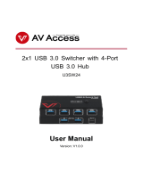
Resetting to Factory-Defaults
To reset the AT-OME-MH21 to factory-default settings, press and hold the RESET button for
approximately 5 seconds. Release the button when the RESET LED indicator begins to ash.
The LED indicator will ash three times to indicate that the reset procedure has completed.
AMS 2.0
Web Server
The AT-OME-MH21 includes a built-in web server, which allows easy management and control of
all features. Follow the instructions below to access the web server.
1. Set the IP mode of the AT-OME-MH21. Refer to IP Conguration (page 8) for more
information.
2. Connect an Ethernet cable from the LAN port on the AT-OME-MH21 to the Local Area
Network (LAN).
3. Connect an HDMI cable from the AT-OME-MH21 to a display, then press the SHOW IP
button on the front panel to display the IP address.
4. Launch a web browser and enter the IP address of the unit.
5. The AT-OME-MH21 Registration page will be displayed.
6. Enter the username, password, and conrm the password on the registration page to
register the device. The password must contain a minimum of 8 characters, including 1
uppercase, 1 lowercase, and 1 numeric character.
7. Click on Register button.
8. The AT-OME-MH21 Login page will be displayed.
9. Enter the username and password login credentials that were entered during the registration
process.
10. Click the Login button
INPUT
21
AT-OME-MH21
DC 5VLANIR OUTRS-232HOST USBUSB HUB
L R
- -
+ +
TXRX TX
OUTPUT
PWR
IP MODE
DISPLAY
AT-OME-MH21
OMEGA
TM
RESET SHOW IPINPUT
21
RESET button
For easy conguration of Atlona devices, AMS 2.0 is available from https://atlona.com/AMS for
free. Once AMS has been setup, following the instructions below.
1. Open a browser on the same network as AMS 2.0 and go to the IP of AMS 2.0. View the
AMS 2.0 installation instructions on how to nd the IP of the software, if necessary.
2. Enter the login information on the AMS 2.0 web page, then click the Login button.
3. View the AT-OME-MH21 manual for routing and conguration information.