Broan CSH4BD Installation guide
- Category
- Heat pumps
- Type
- Installation guide

13 SEERSPLIT SYSTEM HEAT PUMP WITH MICROCHANNEL COILS
T4BD - 042, 048, & 060 (3.5, 4, & 5 TON) SERIES
SINGLE PHASE MODELS
REFRIGERANT CHARGING ............................... 9
Charging the Unit in AC mode ..................................... 9
Charging Charts & Application Notes - (Cooling Only)
10
Figure 6. Charging Chart for 3.5 Ton Units
(TXV Matches)
...........................................10
Figure 7. Charging Chart for 4 Ton Units
(TXV Matches)
........................................... 11
Figure 8. Charging Chart for 5 Ton Units
(TXV Matches)
........................................... 11
Charging Tables & Application Notes - (Cooling Only)
12
Table 5. Charging Table for T4BE-042KA Series
(3.5 Ton Models) – Restrictor Matches
....... 12
Table 6. Charging Table for T4BE-048KA Series
(4 Ton Models) – Restrictor Matches
..........12
Table 7. Charging Table for T4BE-060KA Series
(5 Ton Models) – Restrictor Matches
..........13
Heat Mode Tables & Application Notes (Heating Only)
.14
Table 8. Heat Mode Table for 3.5 Ton Models
..........15
Table 9. Heat Mode Table for 4 Ton Models
.............15
Table 10. Heat Mode Table for 5 Ton Models
...........15
WIRING DIAGRAMS ............................................ 16
Figure 9. Wiring Diagram for 3.5 - 5 Ton Models
Equipped With CoreSense
TM
Diagnostic
Module
........................................................16
Figure 10. Wiring Diagram for 3.5 - 5 Ton Models
NOT Equipped With CoreSense
TM
Diagnostic Module ....................................17
Figure 11. Wiring Diagram for 3.5 - 5 Ton Models
Equipped with Low Pressure Switch
........18
INSTALLATION / PERFORMANCE CHECKLIST 20
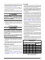
IMPORTANT
It is your responsibility to know this product better than your customer. This includes being able to install the product
according to strict safety guidelines and instructing the customer on how to operate and maintain the equipment for
the life of the product. Safety should always be the deciding factor when installing this product and using common
sense plays an important role as well. Pay attention to all safety warnings and any other special notes highlighted
in the manual. Improper installation of the furnace or failure to follow safety warnings could result in serious injury,
death, or property damage.
These instructions are primarily intended to assist qualified individuals experienced in the proper installation of
this appliance. Some local codes require licensed installation/service personnel for this type of equipment. Please
read all instructions carefully before starting the installation. Return these instructions to the customer’s package
for future reference.
DO NOT DESTROY. PLEASE READ CAREFULLY & KEEP IN A SAFE PLACE FOR FUTURE REFERENCE.
INSTALLATION INSTRUCTIONS
IMPORTANT SAFETY INFORMATION ............... 2
HEAT PUMP INSTALLATION .............................. 3
General Information ..................................................... 3
Before You Install the Heat Pump
................................3
Locating the Heat Pump
..............................................3
Packaging Removal
.....................................................3
Ground Level
...............................................................3
Rooftop
........................................................................3
Connecting Refrigerant Tubing Between the Indoor
& Outdoor Unit
............................................................. 4
Outdoor Orifice Removal & Installation
........................4
ELECTRICAL WIRING ......................................... 5
Pre-Electrical Checklist ................................................5
Line Voltage
.................................................................5
Grounding
.................................................................... 6
Thermostat / Low Voltage Connections
.......................6
CoreSense
TM
Diagnostics Module................................6
Compressor Protection
..............................................7
Resetting Alert Codes
................................................7
START UP & ADJUSTMENTS ............................ 7
Pre-Start Check List .....................................................7
Start-Up Procedures
.................................................... 7
Air Circulation - Indoor Blower
.....................................7
Short Cycle Protection
................................................. 7
System Cooling
............................................................8
System Heating
............................................................8
Defrost Control Board Test Pins
.................................. 8
HEAT PUMP MAINTENANCE ............................. 9

2
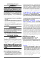
IMPORTANT SAFETY INFORMATION
INSTALLER: Please read all instructions before servicing
this equipment. Pay attention to all safety warnings and
any other special notes highlighted in the manual. Safety
markings are used frequently throughout this manual to
designate a degree or level of seriousness and should not
be ignored. WARNING indicates a potentially hazardous
situation that if not avoided, could result in personal injury
or death. CAUTION indicates a potentially hazardous
situation that if not avoided, may result in minor or moderate
injury or property damage.
WARNING:
ELECTRICAL SHOCK, FIRE OR
EXPLOSION HAZARD
Failure to follow safety warnings exactly could
result in serious injury or property damage.
Improper servicing could result in dangerous
operation, serious injury, death or property
damage.
• Before servicing, disconnect all electrical
power to the indoor blower.
• Whenservicingcontrols,labelallwiresprior
to disconnecting. Reconnect wires correctly.
• Verifyproperoperationafterservicing.
WARNING:
This split system heat pumps is shipped charged
with R410A refrigerant and ready for installation.
If repairs make it necessary for evacuation and
charging, it should only be attempted by qualified
trained personnel thoroughly familiar with this
equipment. Under no circumstances should
the owner attempt to install and/or service this
equipment. Failure to comply with this warning
could result in property damage, personal injury,
or death.
CAUTION:
This unit uses R-410A refrigerant. DO NOT use
any other refrigerant in this unit. Use of another
refrigerant will damage the unit.
WARNING:
Unless noted otherwise in these instructions, only
factory authorized parts or accessory kits may
be used with this product. Improper installation,
service, adjustment, or maintenance may cause
explosion, fire, electrical shock or other hazardous
conditions which may result in personal injury
or property damage.
• Installation of equipment may require brazing
operations. Installer must comply with safety codes
and wear appropriate safety equipment (safety glasses,
work gloves, fire extinguisher, etc.) when performing
brazing operations.
• Followallprecautionsin theliterature,ontags,and
on labels provided with the equipment. Read and
thoroughly understand the instructions provided with
the equipment prior to performing the installation and
operational checkout of the equipment.
• Usecautionwhenhandlingthisapplianceorremoving
components. Personal injury can occur from sharp
metal edges present in all sheet metal constructed
equipment.
WARNING:
The information listed below and the next page
must be followed during the installation, service,
and operation of this furnace. Failure to follow
safety recommendations could result in possible
damage to the equipment, serious personal injury
or death.
• The installer must comply with all local codes and
regulations which govern the installation of this type
of equipment. Local codes and regulations take
precedence over any recommendations contained in
these instructions. Consult local building codes and the
National Electrical Code (ANSI CI) for special installation
requirements.
• Allelectricalwiringmustbecompletedinaccordance
with local, state and national codes and regulations
and with the National Electric Code (ANSI/NFPA 70)
or in Canada the Canadian Electric Code Part 1 CSA
C.22.1.
• Thisequipmentcontainsliquidandgaseousrefrigerant
under high pressure. DO NOT USE ANY PORTION OF
THE CHARGE FOR PURGING OR LEAK TESTING.
Installation or servicing should only be performed by
qualified trained personnel thoroughly familiar with this
type equipment.
• Fullyannealed,refrigerantgradecoppertubingshould
be used when installing the system. Refrigerant suction
line tubing should be fully insulated.
• Thisunitisdesignedforoutdoorinstallationsonlyand
should be positioned as described on page 3.

3
HEAT PUMP INSTALLATION
General Information
Split system heat pumps are designed only for outdoor
rooftop or ground level installations. This unit has been
tested for capacity and efficiency in accordance with
AHRI Standards and will provide many years of safe
and dependable comfort, providing it is properly installed
and maintained. Abuse, improper use, and/or improper
maintenance can shorten the life of the appliance and
create unsafe hazards.
To achieve optimum performance and minimize equipment
failure, it is recommended that periodic maintenance be
performed on this unit. The ability to properly perform
maintenance on this equipment requires certain
mechanical skills and tools.
Refer to the Quick Reference Data sheet for additional
electrical, charging and unit information.
Before You Install the Heat Pump
√ The cooling load of the area to be conditioned must be
calculated and a system of the proper capacity selected.
It is recommended that the area to be conditioned be
completely insulated and vapor sealed.
√ Check the electrical supply and verify the power supply
is adequate for unit operation. The system must be wired
and provided with circuit protection in accordance with
local building codes. If there is any question concerning
the power supply, contact the local power company.
√ The indoor section (air handler, furnace, etc) should be
installed before routing the refrigerant tubing. Refer to
the indoor unit's installation instructions for installation
details.
√ All units are securely packed at the time of shipment and
upon arrival should be carefully inspected for damage
prior to installing the equipment at the job site. Verify
coil fins are straight. If necessary, comb fins to remove
flattened or bent fins. Claims for damage (apparent or
concealed) should be filed immediately with the carrier.
√ Please consult your dealer for maintenance information
and availability of maintenance contracts. Please read
all instructions before installing the unit.
Locating the Heat Pump
• Surveythejobsitetodeterminethebestlocationfor
mounting the outdoor unit.
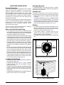
• Overhead obstructions (Figure 1), poorly ventilated
areas, and areas subject to accumulation of debris
should be avoided.
• Sufcientclearanceforunobstructedairowthroughthe
outdoor coil must be maintained in order to achieve rated
performance. See Figure 1 for minimum clearances to
obstructions.
• Considerationshouldbegiventoavailabilityofelectric
power, service access, noise, and shade.
Packaging Removal
To prevent damage to the tubing onnections, carefully
remove the carton and user’s manual from the equipment.
Discard the shipping carton.
Ground Level
Ground level installations must be located according to
local building codes or ordinances and these requirements:
• Clearancesmustbeinaccordancewiththoseshown
in Figure 1.
• A suitable mounting pad must be provided and be
separate from the building foundation. The pad must
be level and strong enough to support the unit’s weight.
The slab height must be a minimum of 2” (5 cm) above
grade and with adequate drainage. See Figure 1.
Rooftop
• The method of mounting should be designed so that it
does not overload roof structures or transmit noise to
the interior of the structure. The roof must be structurally
capable of handling the weight of the unit.
• Full perimeter support is required under the unit.
Support must be made of weather resistant materials
and installed prior to unit installation.
• Thesupportmustbebuilttoraisetheunit6"abovethe
roof.
Figure 1. Clearance Requirements
6"
24" for
Service Access
12" See
Note
12"
See Note
DO NOT
OBSTRUCT
TOP OF UNIT
NOTE: Units require full perimeter clearances. Installer must maintain
18” between two units or 12” between single unit and structure.
Building or Structure
2”
48”

4
Connecting Refrigerant Tubing Between
the Indoor & Outdoor Unit
CAUTION:
When servicing, cover or seal openings to
minimize the exposure of the refrigerant system
to air to prevent accumulation of moisture and
other contaminants.
After outdoor and indoor unit placement has been
determined, route refrigerant tubing between the
equipment in accordance with sound installation practices.
• When connecting refrigerant linesets together, it is
recommended that dry nitrogen be flowing through the
joints during brazing. This will prevent internal oxidation
and scaling from occurring.
• Refrigeranttubingshouldberoutedinamannerthat
minimizes the length of tubing and the number of bends
in the tubing.
• Refrigeranttubingshouldbesupportedinamanner
that the tubing will not vibrate or abrade during system
operation.
• Tubingshouldbekeptcleanofforeigndebrisduring
installation.
• Everyeffortshouldbemadebytheinstallertoensure
that the field installed refrigerant containing components
of the system have been installed in accordance with
these instructions and sound installation practices to
insure reliable system operation and longevity.
• The maximum recommended interconnecting
refrigerant line length is 75 feet, and the vertical elevation
difference between the indoor and outdoor sections
should not exceed 20 feet.
• If precise forming of refrigerant lines is required, a
copper tubing bender is recommended. Avoid sharp
bends and contact of the refrigerant lines with metal
surfaces.
• A lter dryer is provided with the unit and must be
installed in the liquid line of the system. If the installation
replaces a system with a filter dryer already present
in the liquid line, the filter dryer must be replaced with
the one supplied with the unit. The filter dryer must be
installed in strict accordance with the manufacturer’s
installation instructions.
• Optionalequipmentsuchasliquidlinesolenoidvalves,
low ambient, etc., should be installed in strict accordance
with the manufacturer’s installation instructions.
Outdoor Orifice Removal & Installation
The orifice installed in the outdoor unit has been sized
for use with the most popularly matched indoor units.
Depending on the indoor coil that the unit is being matched
with, the outdoor restrictor may need to be changed. Please
refer to the Quick Reference Data sheet that is supplied
with the outdoor unit for more information.
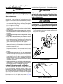
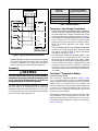
If the outdoor unit has the liquid valve shown in Figure
2 then the restrictor is located inside the swivel nut
connection of the liquid valve and not inside the outdoor
unit’s distributor. Perform steps 1 - 5 if the outdoor restrictor
needs to be changed.
CAUTION:
When servicing, cover or seal openings to
minimize the exposure of the refrigerant system
to air to prevent accumulation of moisture and
other contaminants.
CAUTION:
To prevent damage to the unit or internal
components, it is recommended that two
wrenches be used when loosening or tightening
nuts. Do not over tighten!
1. Using two wrenches loosen the nut and liquid valve.
Turn the assembly nut counter-clockwise until the orifice
body halves are separated.
Liquid
Valve
Restrictor
Swivel Nut
Figure 3. Removal of Orifice
Figure 2. LiquidValve,Restrictor,&
Swivel Nut Adapter

5
LineVoltage
• Awiringdiagramislocatedontheinsidecoverofthe
electrical box of the outdoor unit. The installer should
become familiar with the wiring diagram before making
any electrical connections to the outdoor unit.
• An electrical disconnect must be located within
sight of and readily accessible to the unit. This
switch shall be capable of electrically de-energizing
the outdoor unit.
• Line voltage to the unit should be supplied from a
dedicated branch circuit containing the correct fuse
or circuit breaker for the unit. Incoming field wiring
and minimum size of electrical conductors and circuit
protection must be in compliance with information listed
on the outdoor unit data label. Any other wiring methods
must be acceptable to authority having jurisdiction.
• Theoutdoorunitrequiresbothpowerandcontrolcircuit
electrical connections. Refer to the wiring diagrams
(Figure 9, (page 16), Figure 10, (page 17), &
Figure 11, (page 18)) for identification and location
of outdoor unit field wiring interfaces. Make all electrical
connections in accordance with all applicable codes
and ordinances.
• Overcurrentprotectionmustbeprovidedatthebranch
circuit distribution panel and sized as shown on the unit
rating label and according to applicable local codes.
See the unit rating plate for minimum circuit ampacity
and maximum overcurrent protection limits.
• Providepowersupplyfortheunitinaccordancewiththe
unit wiring diagram, and the unit rating plate. Connect
the line-voltage leads to the terminals on the contactor
inside the control compartment.
• Useonlycopperwireforthelinevoltagepowersupply
to this unit as listed in Table 1. Use proper code agency
listed conduit and a conduit connector for connecting
the supply wires to the unit. Use of rain tight conduit
is recommended.
• 208/230Voltunitsareshippedfromthefactorywired
for 230 volt operation. For 208V operation, remove the
lead from the transformer terminal marked 240V and
connect it to the terminal marked 208V.
2. Insert a light-gauge wire hook between the valve body
and the restrictor orifice while being careful not to scratch
either part. Carefully remove the restrictor orifice from
the valve body. See Figure 3, (page 4).
3. Check the actual size of the new orifice. NOTE: The
size is stamped on its side. Do not use pin gauges to
measure the orifice diameter.
4. Insert the new orifice into the valve body, with the
rounded end facing into the valve. See Figure 2, (page
4).
CAUTION:
To prevent damage to the unit or internal
components, it is recommended that two
wrenches be used when loosening or tightening
nuts. Do not over tighten!
5. Realign the assembly nut on the valve body and hand
tighten both components. Mark a line on both bodies and
then tighten an additional ¼ turn using two wrenches.
The movement of the two lines will show how much the
nut is tightened.
ELECTRICAL WIRING
WARNING:
To avoid risk of electrical shock, personal
injury, or death, disconnect all electrical power
to the unit before performing any maintenance
or service. The unit may have more than one
electrical supply.
Label all wires prior to disconnection when
servicing the unit. Wiring errors can cause
improper and dangerous operation
• Allelectricalconnectionsmustbeincompliancewith
all applicable local codes and ordinances, and with the
current revision of the National Electric Code (ANSI/
NFPA 70).
• ForCanadianinstallationstheelectricalconnections
and grounding shall comply with the current Canadian
Electrical Code (CSA C22.1 and/or local codes).
Pre-Electrical Checklist
√ Verify that the voltage, frequency, and phase of the
supply source match the specifications on the unit
rating plate.
√ Verify that the service provided by the utility is sufficient
to handle the additional load imposed by this equipment.
Refer to the unit wiring label for proper high and low
voltage wiring.
√ Verify factory wiring is in accordance with the units
wiring diagram (Figure 9, (page 16), Figure 10, (page
17), & Figure 11, (page 18)). Inspect for loose
connections.
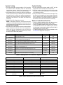
COPPER WIRE SIZE — AWG
(1%VOLTAGEDROP)
SUPPLY WIRE LENGTH-FEET
SUPPLY CIRCUIT
AMPACITY
200 150 100 50
6 8 10 14 15
4 6 8 12 20
4 6 8 10 25
4 4 6 10 30
3 4 6 8 35
3 4 6 8 40
2 3 4 6 45
2 3 4 6 50
2 3 4 6 55
1 2 3 4 60
Wire Size based on N.E.C. for 60° type copper conductors.
Table 1. Copper Wire Size

6
G
RW2
C
E
O
Y
Thermostat
Green
Red
White
G
R
Black
O
Y1 IN
R
C
Air Handler
Heat Pump
(OD Section)
C
W
W2 OUT
W2 IN
Figure 4. Typical Thermostat Connections
Thermostat/LowVoltageConnections
• Thermostatconnectionsshouldbemadeinaccordance
with the instructions supplied with the thermostat and
the indoor equipment. A typical installation with a heat
pump thermostat and air handler is shown in Figure 4.
• Theoutdoorunitisdesignedtooperatefroma24VAC
Class II control circuit. The control circuit wiring must
comply with the current provisions of the NEC (ANSI/
NFPA 70) and with applicable local codes having
jurisdiction.
• Thelowvoltagewiresmustbeproperlyconnectedto
the units low voltage terminal block. Recommended
wire gauge and wire lengths for typical thermostat
connections are listed in Table 2.
• The thermostat should be mounted about 5 feet
above the floor on an inside wall. DO NOT install the
thermostat on an outside wall or any other location
where its operation may be adversely affected by radiant
heat from fireplaces, sunlight, or lighting fixtures, and
convective heat from warm air registers or electrical
appliances. Refer to the thermostat manufacturer’s
instruction sheet for detailed mounting and installation
information.
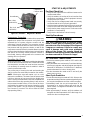
CoreSense
TM
Diagnostics Module
(Select Models Only)
The CoreSense
TM
Diagnostics Module (Figure 5, (page
7)) is a breakthrough innovation for troubleshooting
heat pump and air conditioning system failures. The module
installs easily in the electrical box of the outdoor unit
near the compressor contactor.By using the compressor
as a sensor, CoreSense Diagnostics helps the service
technician more accurately troubleshoot system and
compressor fault conditions.
A flashing LED indicator communicates the ALERT code
and a diagnostic key is also imprinted on the side of the
module to quickly direct the technician to the root cause
of a problem. Alert identification codes are also listed in
Table 3, (page 8).
• Optionalequipmentrequiringconnectiontothepower
or control circuits must be wired in strict accordance
of the NEC (ANSI/NFPA 70), applicable local codes,
and the instructions provided with the equipment.
Grounding
WARNING:
The unit cabinet must have an uninterrupted or
unbroken electrical ground to minimize personal
injury if an electrical fault should occur. Do not
use gas piping as an electrical ground!
This unit must be electrically grounded in accordance
with local codes or, in the absence of local codes, with
the National Electrical Code (ANSI/NFPA 70) or the CSA
C22.1 Electrical Code. Use the grounding lug provided in
the control box for grounding the unit.
Table 2. Thermostat Wire
THERMOSTAT
WIRE GAUGE
MAXIMUM RECOMMENDED
THERMOSTAT WIRE LENGTH (FT)
24 25
22 45
20 70
18 110

7
Figure 5. CoreSense
TM
Diagnostics Module
Compressor
Common Wire
Reset Button
Trip / Lock
(Red LED)
Run / Alert
(Yellow LED)
Compressor Protection
The CoreSense
TM
Diagnostics module utilizes proprietary
algorithms to protect the compressor and system from
repeated trips of system pressure controls and the
compressor internal overload. The protection terminal
of the module should be wired in series with the system
low pressure and high pressure cutouts, as well as the
compressor contactor. When the module detects a series
of trips as described below, it will activate a lockout feature
that opens the normally closed protection contacts in
the module, thereby cutting power to the contactor and
shutting off the compressor.
Resetting Alert Codes
When the CoreSense
TM
Diagnostics module has detected a
series of adverse conditions that have caused it to lockout
the compressor, and after the issue has been resolved,
it is necessary to manually reset the module in order to
clear the present alert code.
The primary way of clearing the code and resetting the
alert is to press the reset button located on the module.
NOTE: Pressing the reset will require a pin or a mini
electronics screwdriver. This button must be pressed and
held for a minimum of one second for the module to be
reset. Pressing the reset button clears the immediate lock
code and the seven day operating history. It will not clear
the permanent module history. In the case of the three-
wire module, the codes can be reset or cleared by cycling
power to the module. This can be done by disengaging
the Common (C) terminal. This will not clear the seven
day operating history.
START UP & ADJUSTMENTS
Pre-Start Check List
√ Verify the unit is level and has sufficient clearances for
unobstructed airflow.
√ Verify the outdoor coil and top of the unit are free from
obstructions and debris, and all equipment access/
control panels are in place.
√ Verify that the line voltage power leads are securely
connected and the unit is properly grounded.
√ Verify that the low voltage wires are securely connected
to the correct leads on the low voltage terminal strip.
√ Verify that the power supply branch circuit overcurrent
protection is sized properly.
√ Verify that the thermostat is wired correctly.
Start-Up Procedures
WARNING:
This unit is equipped with a crankcase heater.
Allow 24 hours prior to continuing the start up
procedures to allow for heating of the refrigerant
compressor crankcase. Failure to comply may
result in damage and could cause premature
failure of the system. This warning should be
followed at initial start up and any time the power
has been removed for 12 hours or longer.
Air Circulation - Indoor Blower
1. Set the thermostat system mode on OFF and the fan
mode to ON.
2. Verify the blower runs continuously. Check the air delivery
at the supply registers and adjust register openings for
balanced air distribution. If insufficient air is detected,
examine ductwork for leaks or obstructions.
3. Set the thermostat fan mode to AUTO and verify the
blower stops running.
Short Cycle Protection
1. Set the thermostat system mode to COOL. Observe the
temperature setting of the thermostat and gradually raise
the set-point temperature until the unit de-energizes.
2. Immediately lower the set point temperature of the
thermostat to its original setting and verify that the
indoor blower is energized and outdoor unit remains
de-energized.
3. After approximately 5 minutes, verify the outdoor unit
energizes and the temperature of the discharge air is
cooler than the room temperature.

8
System Cooling
1. Set the thermostat’s system mode to COOL and the
fan mode to AUTO. Gradually lower the thermostat
temperature setpoint below room temperature and
verify the outdoor unit and indoor blower energize.
2. Verify blower wheel is spinning in direction indicated by
arrow. Feel the air being circulated by the indoor blower
and verify that it is cooler than ambient temperature.
Listen for any unusual noises. If unusual sounds occur,
determine the source of the noise and correct as
necessary.
3. Verify HI and LO refrigerant pressures.
NOTE: If refrigerant pressures are abnormal and the
compressor is rotating backwards, shut off main power to
the unit and switch any two field wires at the disconnect.
DO NOT alter unit wiring.
4. Allow the system to operate for several minutes and then
set the temperature selector above room temperature.
Verify the fan and compressor cycle off with the
thermostat. NOTE: The blower should also stop unless
fan switch is set to the ON position.
Table 3. LED Diagnostics for CoreSense
TM
Diagnostics Module
ALERT CODE ALERT CONDITION LOCKLEVEL LOCK INDICATION
Normal Run
Solid Yellow
Normal operation, no trip N/A N/A
Code1
Yellow Flash 1
Long run time. Compressor is on running for more than 18 hours.
(Code1 is disabled in Heat Pump Mode)
N/A N/A
Code2
Yellow Flash 2
Compressor (pressure) trip. Compressor runs for 12 sec to 15 min followed
by a compressor trip condition lasting for more than 7 min.
4x consecutive
Red: Flash2
Yellow: Off
Code3
Yellow Flash 3
Pressure switch cycling. Compressor runs for 12 sec to 15 min followed
by a compressor trip lasting between 35 sec to 7 min.
4x consecutive
or 10x total
Red: Flash3
Yellow: Off
Code4
Yellow Flash 4
Locked rotor. Compressor trips within a compressor run time of 12 sec
and does not start within 35 sec.
10x consecutive
Red: Flash4
Yellow: Off
Code5
Yellow Flash 5
Compressor (moderate run) trip. Compressor runs for 15 min to 18 hrs
followed by a compressor trip lasting longer than 7 min.
4x consecutive
or 10x total
Red: Flash5
Yellow: Off
Code9
Red Flash 9
The current to the PROT terminal is greater than 2A.
Current >2A
for 40ms
Red: Flash9
Yellow: Off
Trip
Solid Red
Demand is present, but compressor is not running. N/A N/A
STATUS INDICATOR STATUS TYPE DIAGNOSTIC DESCRIPTION
C1
Operating Status Cooling, 1st Stage
H1
Operating Status Heating, 1st Stage
SC
Operating Status Anti Short Cycle Timer
dF
Operating Status Defrost
_.
Operating Status Power on, no call for operation
01
Fault Pressure switch, low
02
Fault Pressure switch, high
03
Fault Temperature Sensor, Ambient
04
Fault Temperature Sensor, Coil
05
Fault Board
dF
(FLASHING)
Input Error
Forced defrost - test short applied longer than
11 minutes
Table 4. Status Indicators for Defrost Control Board
System Heating
1. Set the thermostat's system mode to HEAT and the
temperature mode to below room temperature.
2. Verify the outdoor unit and indoor fan stop running. After
5 minutes, increase the temperature on the thermostat
to it's maximum setting.
3. Verify the outdoor unit and indoor blower energize. Feel
the air being circulated by the indoor blower and verify
that it is warmer than ambient temperature. Listen for
any unusual noises. If unusual sounds occur, determine
the source of the noise and correct as necessary.
Defrost Control Board Test Pins
• Placingajumperbetweenthetestpinsforlessthan1
second will bypass the Anti-Short Cycle Timer.
• Placingajumperbetweenthetestpinsformorethan1
second will force the unit into a defrost cycle. As soon
as the jumper is removed, the defrost cycle will end as
determined by the typical criteria.
• Todetermineoperatingstatusorfaultconditions,refer
to Table 4 for diagnostic description.

9
HEAT PUMP MAINTENANCE
WARNING:
To prevent electrical shock, personal injury, or
death, disconnect all electrical power to the unit
before performing any maintenance or service.
The unit may have more than one electrical supply.
Proper maintenance is important to achieve optimum
performance from the heat pump. The ability to properly
perform maintenance on this equipment requires certain
mechanical skills and tools. If you do not possess these
skills, contact your dealer for maintenance. Consult your
local dealer about the availability of maintenance contracts.
Routine maintenance should include the following:
• Inspectandcleanorreplaceairltersatthebeginning
of each heating and cooling season, or more frequently
if required.
• Inspecttheoutdoorcoilatthebeginningofeachcooling
season. Remove any debris. Clean the outdoor coil
and louvers as necessary using a mild detergent and
water. Rinse thoroughly with water.
• Inspecttheelectricalconnectionsfortightnessatthe
beginning of each heating and cooling season. Service
as necessary.
CAUTION:
The unit should never be operated without a
filter in the return air system. Replace disposable
filters with the same type and size.
• Donotaddadditionaloiltomotorsunequippedwithoil
tubes. The compressor is hermetically sealed at the
factory and does not require lubrication.
REFRIGERANT CHARGING
WARNING:
This split system heat pump is shipped charged
with R410A refrigerant and ready for installation.
If repairs make it necessary for evacuation and
charging, it should only be attempted by qualified
trained personnel thoroughly familiar with this
equipment. Under no circumstances should
the owner attempt to install and/or service this
equipment. Failure to comply with this warning
could result in property damage, personal injury,
or death.
After refrigerant line connections are completed, it is
required that you leak check and evacuate the indoor
section and all line connections (using proper methods)
before finalizing the full system refrigerant charge.
• Toachieveratedcapacityandefciency,thecompressor
must be exposed to refrigerant for at least 24 hours
prior to running and then the compressor must be run
for a minimum of 12 hours.
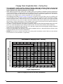
• Cooling mode charging charts are applicable only
to matched assemblies of this equipment and listed
airflows for the indoor coil. Refer to the Quick Reference
Data sheet for additional charging information.
Outdoor units with non-AHRI listed indoor coils are not
recommended and deviations from rated airflows or
non-listed combinations may require modification to the
expansion device and refrigerant charging procedures
for proper and efficient system operation. Refer to Figure
6, (page 10), Figure 7, (page 11), & Figure 8, (page
11) and Table 5, (page 12), Table 6, (page 12),
& Table 7, (page 13) for correct system charging.
• Therefrigerantchargecanbecheckedandadjusted
through the service ports provided external to the
outdoor unit. Use only gage line sets which have a
“Schrader” depression device present to actuate the
valve. A common suction port for heating mode charging
is included and located on the compressor access panel
above the outdoor unit service valves.
• Heat mode tables (Table 8, (page 15), Table 9,
(page 15), & Table 10, (page 15)) are provided
for quick reference when the unit is in heating mode
and for the inspection of the liquid line pressures and
temperatures.
• Ahigh-pressureswitchisfactory-installedandlocated
in the compressor discharge line internal to the
outdoor unit. The switch is designed to de-energize
the system when very high pressures occur during
abnormal conditions. Under normal conditions, the
switch is closed. If the discharge pressure rises above
575 psig, then the switch will open and de-energize
the outdoor unit. The switch will close again once the
liquid pressure decreases to 460 psig. Please note that
the switch interrupts the thermostat inputs to the unit.
When the switch opens and then closes, there will be
a 5 minute short cycling delay before the outdoor unit
will energize.
Charging the Unit in AC mode
(At outdoor temperatures above 55° F for
optimized sub-cooling of 10° F - 12° F.)
1. With the system operating at steady-state, measure the
liquid refrigerant pressure (in psig) at the outdoor unit
service valve.
2. Measure the liquid refrigerant temperature (in
Fahrenheit) at the service valve.
3. Determine the required liquid refrigerant pressure from
Figure 6, (page 10), Figure 7, (page 11), & Figure
8, (page 11).
• IfthepressuremeasuredinStep1isgreaterthan
the required liquid refrigerant pressure determined in
Step 3, then there is too much charge in the system.
Remove refrigerant and repeat Steps 1 through 3
until the system is correctly charged.
• IfthepressuremeasuredinStep1islessthanthe
required liquid refrigerant pressure determined in
Step 3, there is too little charge in the system. Add
refrigerant and repeat Steps 1 through 3 until the
system is correctly charged.

10
Charging Charts & Application Notes - (Cooling Only)
• This equipment’s cooling system contains refrigerant under high pressure. Always use safe and
environmentally sound methods when handling refrigerant handling or servicing the unit. Review the
factory literature and safety warnings prior to servicing.
• Whenrepairingsystemleaks,alwaysuseanitrogen(inert)gastoprotecttherefrigerantsystemandpressure
check the repair before re-charging. Always replace the filter-dryers when performing any repair to the refrigeration
system with one capable of acid removal. After completing the repairs, evacuate the system to 350 - 500 microns
and weigh in the refrigerant to the amount specified on the unit rating label.
• Thechargingchartsbelow(Figure 6, Figure 7, & Figure 8 are valid for a variety of indoor, return air conditions and
are most influenced by the outdoor ambient temperature, outdoor fan operation and the unit operating voltage.
Before using these charts, make sure the unit is in a stable operating mode. As shown in the charts, the ideal
system sub-cooling can vary over the range of operation. Reference the charts to determine the ideal amount of
sub-cooling for a given liquid pressure. Units charged to other values will not perform at the rated unit efficiency
(EER) or rated Coefficient of Performance (COP) in heating mode.
• Toinspectasystemsoperationusingqualityinstruments,matchthemeasuredliquidtemperaturetotheunits
chart. The measured liquid pressure reading should be within 3% of the charts value for most installations.
• Forsystemsthatareoperatingwithmorethana5%deviation,inspecttheunitforthepropervoltageandphase
balance and the refrigeration system for leaks.
• Unitsthatareoperatingatlessthen95%ofthenominalvoltageorwitha2%phaseimbalancemayseeamore
significant deviation than the amount stated above.
• DO NOT use the charts in systems that have a fan cycling under low-ambient control. Refer to the low-ambient
kit instructions for more information. (If applicable)
200
220
240
260
280
300
320
340
360
380
400
420
440
460
480
500
520
540
560
580
600
75 80 85 90 95 100105 110115 120 125 13
01
35
Liquid Temperature (
0
F)
Liquid Pressure (psig)
Remove refrigerant when above the curve
Add refrigerant when below the curve
T4BD-042KA Charging Chart - Cooling
Figure 6. ChargingChartfor3.5TonUnits(TXVMatches)

11
200
220
240
260
280
300
320
340
360
380
400
420
440
460
480
500
520
540
560
580
600
75 80 85 90 95 100105 110115 120 125 13
01
35
Liquid Temperature (
0
F)
Liquid Pressure (psig)
Remove refrigerant when above the curve
Add refrigerant when below the curve
T4BD-048KA Charging Chart - Cooling
Figure 7. ChargingChartfor4TonUnits(TXVMatches)
200
220
240
260
280
300
320
340
360
380
400
420
440
460
480
500
520
540
560
580
600
75 80 85 90 95 100105 110115 120 125 13
01
35
Liquid Temperature (
0
F)
Liquid Pressure (psig)
Remove refrigerant when above the curve
Add refrigerant when below the curve
T4BD-060KA Charging Chart - Cooling
Figure 8. ChargingChartfor5TonUnits(TXVMatches)

12
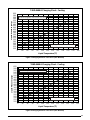
Table 5. Charging Table for T4BE-042KA Series (3.5 Ton Models) – Restrictor Matches
Table 6. Charging Table for T4BE-048KA Series (4 Ton Models) – Restrictor Matches
SUCT.
PRESS.
OUTDOOR TEMPERATURE (°F)
70 75 80 85 90 95 100 105
LIQ.
PRESS.
DIS.
TEMP.
LIQ.
PRESS.
DIS.
TEMP.
LIQ.
PRESS.
DIS.
TEMP.
LIQ.
PRESS.
DIS.
TEMP.
LIQ.
PRESS.
DIS.
TEMP.
LIQ.
PRESS.
DIS.
TEMP.
LIQ.
PRESS.
DIS.
TEMP.
LIQ.
PRESS.
DIS.
TEMP.
132 248 128
134
248 128
269 133
136 248 128
269 133
290 137
138
248 128
269 133
290 137
310 141
140 249 129
269 133
290 137
311 141
331 146
142 270 133
290 137
311 141
332 146
352 150
144 291 137
311 141
332 146
353 150
373 155
146 312 141
332 146
353 150
373 154
394 159
148 312 141 332 145
353 150
374 154
394 159
150 333 145 353 150
374 154
395 158
152 354 150
374 154
395 158
154 375 154 395 158
156 396 158
158
Charging Tables & Application Notes - (Cooling Only)
Shaded boxes indicate flooded conditions.
Rated design values. The suction pressure will be lower than design value if indoor air flow, entering dry
bulb, or entering wet bulb temperatures are lower than design.
1. All pressures are listed in psig and all temperatures in ° F
2. Discharge temperatures greater than charted values indicate an undercharged system.
3. Discharge temperatures less than charted values indicate an overcharged system.
4 In Cooling Mode, suction pressure will be lower than design value if indoor air flow, entering dry bulb, or entering
wet bulb temperatures are lower than design.
5. In Heating Mode, charge should be weighed in. It is strongly recommended to verify charge in Cooling Mode
at ambient above 70°F.
SUCT.
PRESS.
OUTDOOR TEMPERATURE (°F)
70 75 80 85 90 95 100 105
LIQ.
PRESS.
DIS.
TEMP.
LIQ.
PRESS.
DIS.
TEMP.
LIQ.
PRESS.
DIS.
TEMP.
LIQ.
PRESS.
DIS.
TEMP.
LIQ.
PRESS.
DIS.
TEMP.
LIQ.
PRESS.
DIS.
TEMP.
LIQ.
PRESS.
DIS.
TEMP.
LIQ.
PRESS.
DIS.
TEMP.
130 238 132
132
240 133
260 136
134 243 134
263 137
283 140
136
245 134
265 138
285 141
305 144
138 247 135
268 138
288 141
308 145
328 148
140 270 139
291 142
311 145
331 149
350 152
142 293 143
313 146
333 149
353 153
373 156
144 316 147
336 150
356 153
376 156
396 160
146 319 147 339 151
359 154
379 157
399 160
148 342 151 362 154
382 158
402 161
150 365 155
385 158
405 162
152 388 159 408 162
154 411 163
156

13
Table 7. Charging Table for T4BE-060KA Series (5 Ton Models) – Restrictor Matches
SUCT.
PRESS.
OUTDOOR TEMPERATURE (°F)
70 75 80 85 90 95 100 105
LIQ.
PRESS.
DIS.
TEMP.
LIQ.
PRESS.
DIS.
TEMP.
LIQ.
PRESS.
DIS.
TEMP.
LIQ.
PRESS.
DIS.
TEMP.
LIQ.
PRESS.
DIS.
TEMP.
LIQ.
PRESS.
DIS.
TEMP.
LIQ.
PRESS.
DIS.
TEMP.
LIQ.
PRESS.
DIS.
TEMP.
121 244 135
123
245 135
267 141
125 246 135
268 141
290 147
127
247 136
269 142
291 147
313 154
129 248 136
270 142
292 148
314 154
336 160
131 271 142
293 148
315 154
337 160
359 166
133 295 148
317 154
338 160
360 166
382 172
135 318 154
340 160
362 166
383 172
405 178
137 319 154 341 160
363 166
385 172
406 178
139 342 160 364 166
386 172
408 178
141 365 166
387 172
409 178
143 388 172 410 178
145 411 178
147

14
• ReadallnotesandwarningsfortheCooling-modechargingchartspriortousingtheseHeating-mode
charging charts. Always use safe and environmentally sound methods when handling refrigerant handling
or servicing the unit. Review the factory literature and safety warnings prior to servicing.
• Whenrepairingsystemleaks,alwaysuseanitrogen(inert)gastoprotecttherefrigerantsystemandpressure
check the repair before re-charging. Always replace the filter-dryers when performing any repair to the refrigeration
system with one capable of acid removal. After completing the repairs, evacuate the system to 350 - 500 microns
and weigh in the refrigerant to the amount specified on the unit rating label.
• BeforeusingTable 8, Table 9, & Table 10, determine the outdoor ambient temperature and the return air temperature
to the unit. Locate the appropriate location on the units verification chart based on those measurements to determine
the ideal discharge pressure and temperature. Verify the outdoor fan and compressor are running and the outdoor
coil is free from frost accumulation. Also verify the system is not operating in defrost mode before inspecting the
system.
• Always use quality instruments that are in good working order to measure the actual operating point of the
refrigeration system. The discharge temperature should be within 2 degrees of the ideal value and the pressure
should be within 2%.
• Themostreliablewayofverifyingthesystemisatthecorrectchargeistoevacuatethesystemandweighinthe
charge to the amount shown on the rating label. However, if an inspection with these verification charts does not
line up with the values shown and the ambient temperature is above 50˚ F, then a more accurate way to inspect
the system for proper charge is with the cooling mode charging charts. Switch the unit into cooling mode and
allow it to operate and stabilize for a few minutes then inspect the unit operation with the cooling mode charts and
procedures.
Before changing the unit charge, always inspect the following items first:
1. Inspect the liquid line temperature on the inlet and outlet of the filter dryers. If it is the factory dryer and in good
condition there should be no temperature difference. If the temperature difference is larger than 5˚, replace the filter
dryer with one that is bi-directional and has acid removal capability. Refer to the unit RPL for the recommended
part number and size.
2. Inspect the units input voltage. Units operating at less than 95% of the nominal voltage may deviate more from the
chart then previously stated.
3. Inspect the input voltage for a phase imbalance. Units with greater then a 2% disparity will not operate at the rated
performance.
4. Verify that the unit filters are installed and are clean. The pressure drop across the filters should not exceed 0.08
in-W.C.
5. Inspect the indoor coil, indoor blower and blower motor for cleanliness, clogging, and proper operation.
6. Inspect the system for leaks. If any leaks are detected, repair them immediately. Re-inspect the return air and
ambient temperatures and verify that the correct system point on the verification chart was selected.
DO NOT use the charts in systems that have the fan cycling under a low-ambient control. Low-ambient controls are
for cooling operation. In heating mode, the low ambient control should be disabled. Unless the unit is in defrost mode,
the outdoor fan should always operate in conjunction with the compressor.
IMPORTANT NOTE: If the unit is equipped with a liquid valve with an outdoor restrictor (Figure 2 page 4),
then it is not possible to measure the liquid pressure. To approximate the liquid pressure, subtract 7 psig
from the discharge pressure.
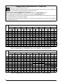
Heat Mode Tables & Application Notes - (Heating Only)
Shaded boxes indicate flooded conditions.
Rated design values. The suction pressure will be lower than design value if indoor air flow, entering dry
bulb, or entering wet bulb temperatures are lower than design.
1. All pressures are listed in psig and all temperatures in ° F
2. Discharge temperatures greater than charted values indicate an undercharged system.
3. Discharge temperatures less than charted values indicate an overcharged system.
4. In Heating Mode, charge should be weighed in. It is strongly recommended to verify charge in Cooling Mode
at ambient above 70°F.

15
OUTDOOR TEMPERATURE (° F)
0 10 20 30 40 50 60
SUC.
PRESS
LIQUID
PRESS.
DISCH.
PRESS.
DISCH.
TEMP.
SUC.
PRESS
LIQUID
PRESS.
DISCH.
PRESS.
DISCH.
TEMP.
SUC.
PRESS
LIQUID
PRESS.
DISCH.
PRESS.
DISCH.
TEMP.
SUC.
PRESS
LIQUID
PRESS.
DISCH.
PRESS.
DISCH.
TEMP.
SUC.
PRESS
LIQUID
PRESS.
DISCH.
PRESS.
DISCH.
TEMP.
SUC.
PRESS
LIQUID
PRESS.
DISCH.
PRESS.
DISCH.
TEMP.
SUC.
PRESS
LIQUID
PRESS.
DISCH.
PRESS.
DISCH.
TEMP.
33 209 216 123 45 232 239 127 57 255 262 130 69 278 285 133 84 294 301 143 102 325 333 160 119 357 364 178
34 216 223 121 46 238 245 125 58 260 267 128 70 282 289 131 85 301 308 140 103 332 340 156 120 364 371 171
35
223 230 119
47
244 251 123
59
265 272 126
71
285
293 129
86
308 315 137
104
339 347 151
121
371 378 165
36 230 237 117 48 250 257 121 60 269 277 124 72 289 296 127 87 315 322 134 105 346 354 147 122 378 385 159
37
237 244 115
49
255 263 119
61
274 281 122
73
293 300 125
88
322 329 132
106
353 361 142
123
385 392 153
38 244 251 113 50 261 269 117 62 279 286 120 74 296 304 123 89 329 336 129 107 360 368 138 124 392 399 147
39 251 258 111 51 267 275 115 63 284 291 118 75 300 307 121 90 336 343 126 108 367 375 133 125 399 406 141
Table 8. Heat Mode Table for 3.5 Ton Models
OUTDOOR TEMPERATURE (° F)
0 10 20 30 40 50 60
SUC.
PRESS
LIQUID
PRESS.
DISCH.
PRESS.
DISCH.
TEMP.
SUC.
PRESS
LIQUID
PRESS.
DISCH.
PRESS.
DISCH.
TEMP.
SUC.
PRESS
LIQUID
PRESS.
DISCH.
PRESS.
DISCH.
TEMP.
SUC.
PRESS
LIQUID
PRESS.
DISCH.
PRESS.
DISCH.
TEMP.
SUC.
PRESS
LIQUID
PRESS.
DISCH.
PRESS.
DISCH.
TEMP.
SUC.
PRESS
LIQUID
PRESS.
DISCH.
PRESS.
DISCH.
TEMP.
SUC.
PRESS
LIQUID
PRESS.
DISCH.
PRESS.
DISCH.
TEMP.
29 214 225 107 44 233 244 114 59 252 263 122 74 271 282 129 89 281 292 139 104 307 318 150 120 332 343 161
30 221 232 105 45 239 250 112 60 257 268 120 75 275 286 127 90 288 299 136 105 314 325 146 121 339 350 155
31
228 239 103
46
245 256 110
61
261 272 118
76
278
289 125
91
295 306 133
106
321 332 141
122
346 357 149
32 235 246 101 47 251 261 108 62 266 277 116 77 282 293 123 92 302 313 130 107 328 339 137 123 353 364 143
33
242 253 99
48
256 267 106
63
271 282 114
78
286 297 121
93
309 320 127
108
335 346 132
124
360 371 137
34 249 260 97 49 262 273 104 64 276 287 112 79 289 300 119 94 316 327 124 109 342 353 128 125 367 378 131
35 256 267 95 50 268 279 102 65 281 292 110 80 293 304 117 95 323 334 122 110 349 360 123 126 374 385 124
Table 9. Heat Mode Table for 4 Ton Models
OUTDOOR TEMPERATURE (° F)
0 10 20 30 40 50 60
SUC.
PRESS
LIQUID
PRESS.
DISCH.
PRESS.
DISCH.
TEMP.
SUC.
PRESS
LIQUID
PRESS.
DISCH.
PRESS.
DISCH.
TEMP.
SUC.
PRESS
LIQUID
PRESS.
DISCH.
PRESS.
DISCH.
TEMP.
SUC.
PRESS
LIQUID
PRESS.
DISCH.
PRESS.
DISCH.
TEMP.
SUC.
PRESS
LIQUID
PRESS.
DISCH.
PRESS.
DISCH.
TEMP.
SUC.
PRESS
LIQUID
PRESS.
DISCH.
PRESS.
DISCH.
TEMP.
SUC.
PRESS
LIQUID
PRESS.
DISCH.
PRESS.
DISCH.
TEMP.
26 239 259 148 40 254 273 147 53 269 288 146 67 283 303 145 81 297 316 151 97 332 352 165 112 368 388 180
27 246 266 146 41 260 279 145 54 273 293 144 68 287 307 143 82 304 323 148 98 339 359 161 113 375 395 173
28
253 273 144
42
266 285 143
55
278 298 142
69
291
310 141
83
311 330 146
99
346 366 156
114
382 402 167
29 260 280 142 43 272 291 141 56 283 302 140 70 294 314 139 84 318 337 143 100 353 373 152 115 389 409 161
30
267 287 140
44
278 297 139
57
288 307 138
71
298 318 137
85
325 344 140
101
360 380 147
116
396 416 155
31 274 294 138 45 283 303 137 58 293 312 136 72 302 321 135 86 332 351 137 102 367 387 143 117 403 423 149
32 281 301 136 46 289 309 135 59 297 317 134 73 305 325 133 87 339 358 134 103 374 394 138 118 410 430 143
Table 10. Heat Mode Table for 5 Ton Models

16
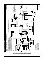
WIRING DIAGRAMS
OUTDOOR
FAN MOTOR
R
C
CC
C
H
F
DUAL
CAPACITOR
(SINGLE PHASE)
FIELD SUPPLY
L1
GRD
L2
GROUNDING
SCREW
C
S
T1
T2
L1 L2
CONTACTOR
R
COMPRESSOR
Y2 IN
FAN2CCH2CCH1
W2 IN
Y1 IN CR
HOT1
HOT2
(24V COM)
OUTDOOR
TEMP
Y1 OUT
RV1
O
LP1LP2HP1HP2
S
CC
DEFROST CONTROL
BOARD
BLACK
YELLOW/
YELLOW BLACK
BLACK/
BLACK WHITE
ORANGE
BLUE
COIL#1
TEMP
RV2
CCH
RVS
HPS
COIL SENSOR
HGBP
AMB SENSOR
YROC EW2
THERMOSTAT
FAN1
W2 OUT
Y2 OUT
RED/RED BLACK
BLACK
RCYP
CORESENSE
BLACK
BLACK
YELLOW
BLACK
BLACK
BLACK
RED
YELLOW
BLACK
RCYP
CORESENSE
CC
Y2 IN
FAN1 FAN2 CCH2 CCH1
W2 INY1 IN CR
HOT1
HOT2
(24V COM)
OUTDOOR
TEMP
Y1 OUT
RV1
O
LP1LP2HP1HP2
COIL#1
TEMP
RV2
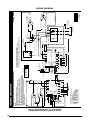
Split System Heat Pump (Outdoor Section) Single Phase
WIRING DIAGRAM
NOTES:
1. Disconnect all power before servicing.
2. For supply connections use copper conductors only.
3. Not suitable on systems that exceed 150 volts to ground
4. For replacement wires use conductors suitable for 105˚ C.
5. For ampacities and overcurrent protection, see unit rating plate.
6. Connect to 24 vac/40va/class 2 circuit. See furnace/air handler
installation instructions for control circuit and optional
relay/transformer kits.
1. Couper le courant avant de faire letretien.
2. Employez uniquement des conducteurs en cuivre.
3. Ne convient pas aux installations de plus de 150 volt a la terre.
711341A
04/13
FIELD WIRING
LEGEND:
LOW VOLTAGE
HIGH VOLTAGE
DUAL CAPACITOR
H
C
F
COMPRESSOR
OUTDOOR FAN MOTOR
R
C
S
L1
T1
L2
T2
DEFROST CONTROL BOARD
208/230V
R
C
S
CCH
RVS
HPS
HGBP
COIL SENSOR
AMB SENSOR
YROC EW2
THERMOSTAT
AMB SENSOR - Ambient Sensor
CC - Contactor Coil
CCH - Crankcase Heater
HPS - High Pressure Switch
HGBP - Hot Gas By Pass Valve
RVS - Reversing Valve Solenoid
* HARD START KIT (OPTIONAL)
W2 OUT
Y2 OUT
START
CAPACITOR*
START RELAY*
5
2
1
YELLOW
BLACK
Figure 9. Wiring Diagram for 3.5 - 5 Ton Models
Equipped With CoreSense
TM
Diagnostic Module

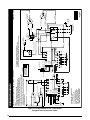
17
OUTDOOR
FAN MOTOR
R
C
CC
C
H
F
DUAL
CAPACITOR
(SINGLE PHASE)
FIELD SUPPLY
L1
GRD
L2
GROUNDING
SCREW
C
S
T1
T2
L1 L2
CONTACTOR
R
COMPRESSOR
Y2 IN
FAN2CCH2CCH1
W2 IN
Y1 IN CR
HOT1
HOT2
(24V COM)
OUTDOOR
TEMP
Y1 OUT
RV1
O
LP1LP2HP1HP2
S
CC
DEFROST CONTROL
BOARD
BLACK
YELLOW/
YELLOW BLACK
BLACK/
BLACK WHITE
ORANGE
BLUE
COIL#1
TEMP
RV2
CCH
RVS
HPS
COIL SENSOR
HGBP
AMB SENSOR
YROC EW2
THERMOSTAT
FAN1
W2 OUT
Y2 OUT
RED/RED BLACK
BLACK
BLACK
BLACK
YELLOW
BLACK
BLACK
BLACK
CC
Y2 IN
FAN1 FAN2 CCH2 CCH1
W2 INY1 IN CR
HOT1
HOT2
(24V COM)
OUTDOOR
TEMP
Y1 OUT
RV1
O
LP1LP2HP1HP2
COIL#1
TEMP
RV2
Split System Heat Pump (Outdoor Section) Single Phase
WIRING DIAGRAM
NOTES:
1. Disconnect all power before servicing.
2. For supply connections use copper conductors only.
3. Not suitable on systems that exceed 150 volts to ground
4. For replacement wires use conductors suitable for 105˚ C.
5. For ampacities and overcurrent protection, see unit rating plate.
6. Connect to 24 vac/40va/class 2 circuit. See furnace/air handler
installation instructions for control circuit and optional
relay/transformer kits.
1. Couper le courant avant de faire letretien.
2. Employez uniquement des conducteurs en cuivre.
3. Ne convient pas aux installations de plus de 150 volt a la terre.
711315A
04/13
FIELD WIRING
LEGEND:
LOW VOLTAGE
HIGH VOLTAGE
DUAL CAPACITOR
H
C
F
COMPRESSOR
OUTDOOR FAN MOTOR
R
C
S
L1
T1
L2
T2
DEFROST CONTROL BOARD
208/230V
R
C
S
CCH
RVS
HPS
HGBP
COIL SENSOR
AMB SENSOR
YROC EW2
THERMOSTAT
AMB SENSOR - Ambient Sensor
CC - Contactor Coil
CCH - Crankcase Heater
HPS - High Pressure Switch
HGBP - Hot Gas By Pass Valve
RVS - Reversing Valve Solenoid
* HARD START KIT (OPTIONAL)
W2 OUT
Y2 OUT
START
CAPACITOR*
START RELAY*
5
2
1
YELLOW
BLACK
Figure 10. Wiring Diagram for 3.5 - 5 Ton Models
NOT Equipped With CoreSense
TM
Diagnostic Module

18
OUTDOOR
FAN MOTOR
R
C
CC
C
H
F
DUAL
CAPACITOR
(SINGLE PHASE)
FIELD SUPPLY
L1
GRD
L2
GROUNDING
SCREW
C
S
T1
T2
L1 L2
CONTACTOR
R
COMPRESSOR
Y2 IN
FAN2CCH2CCH1
W2 IN
Y1 IN CR
HOT1
HOT2
(24V COM)
OUTDOOR
TEMP
Y1 OUT
RV1
O
LP1LP2HP1HP2
S
CC
DEFROST CONTROL
BOARD
BLACK
YELLOW/
YELLOW BLACK
BLACK/
BLACK WHITE
ORANGE
BLUE
COIL#1
TEMP
RV2
CCH
RVS
HPS
COIL SENSOR
HGBP
LPS
AMB SENSOR
YROC EW2
THERMOSTAT
FAN1
W2 OUT
Y2 OUT
RED/RED BLACK
BLACK
BLACK
BLACK
YELLOW
BLACK
BLACK
BLACK
CC
Y2 IN
FAN1 FAN2 CCH2 CCH1
W2 INY1 IN CR
HOT1
HOT2
(24V COM)
OUTDOOR
TEMP
Y1 OUT
RV1
O
LP1LP2HP1HP2
COIL#1
TEMP
RV2
Split System Heat Pump (Outdoor Section) Single Phase
WIRING DIAGRAM
NOTES:
1. Disconnect all power before servicing.
2. For supply connections use copper conductors only.
3. Not suitable on systems that exceed 150 volts to ground
4. For replacement wires use conductors suitable for 105˚ C.
5. For ampacities and overcurrent protection, see unit rating plate.
6. Connect to 24 vac/40va/class 2 circuit. See furnace/air handler
installation instructions for control circuit and optional
relay/transformer kits.
1. Couper le courant avant de faire letretien.
2. Employez uniquement des conducteurs en cuivre.
3. Ne convient pas aux installations de plus de 150 volt a la terre.
711316A
04/13
FIELD WIRING
LEGEND:
LOW VOLTAGE
HIGH VOLTAGE
DUAL CAPACITOR
H
C
F
COMPRESSOR
OUTDOOR FAN MOTOR
R
C
S
L1
T1
L2
T2
DEFROST CONTROL BOARD
208/230V
R
C
S
CCH
RVS
HPS
LPS
HGBP
COIL SENSOR
AMB SENSOR
YROC EW2
THERMOSTAT
AMB SENSOR - Ambient Sensor
CC - Contactor Coil
CCH - Crankcase Heater
HPS - High Pressure Switch
HGBP - Hot Gas By Pass Valve
LPS - Low Pressure Switch
RVS - Reversing Valve Solenoid
* HARD START KIT (OPTIONAL)
W2 OUT
Y2 OUT
START
CAPACITOR*
START RELAY*
5
2
1
YELLOW
BLACK
Figure 11. Wiring Diagram for 3.5 - 5 Ton Models
Equipped with Low Pressure Switch

19

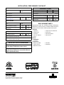
INSTALLATION / PERFORMANCE CHECKLIST
ELECTRICAL SYSTEM
Electrical connections tight? YES NO
Line voltage polarity correct? YES NO
Rated Voltage:
___________________________________ VOLTS
Has the thermostat been calibrated? YES NO
Is the thermostat level? YES NO
Is the heat anticipator setting correct?
(If Applicable)
YES NO
REFRIGERATION SYSTEM
Was unit given 24 hr warm up period
for crankcase heaters?
YES NO
Stage-1 Liquid Pressure (high side)
________________________
Stage-1 Suction Pressure (low side) ________________________
INSTALLATION ADDRESS:
CITY ________________________ STATE ________________
UNIT MODEL # ________________________________________
UNIT SERIAL # ________________________________________
Unit Installed Minimum clearances per
Figure 1, (page 3)?
YES NO
INSTALLER NAME:
CITY
_______________________ STATE ________________
Has the owner’s information been
reviewed with the customer?
YES NO
Has the Literature Package been left
with the unit?
YES NO
7096810 (NEW)
PROPOSITION 65 WARNING:
WARNING: This product contains chemicals known
to the state of California to cause cancer.
WARNING: This product contains chemicals known
to the state of California to cause birth defects or
other reproductive harm.
Specifications & illustrations subject to change
without notice or incurring obligations (01/14).
REPLACEMENT PARTS
Replacement parts are available through all Nordyne
distributors. Please have the complete model and serial
number of the unit when ordering replacement parts.
Electrical:
• Capacitors
• TemperatureLimitSwitches
• Compressors • Thermostats
• Contactors • TimeDelayRelays
• PressureSwitches • Transformers
• Relays
Motors:
• BlowerMotor
• FanMotor
Components:
• BlowerAssembly • FanGrille
• CabinetPanels • Filter/Driers
• ExpansionValves
-
 1
1
-
 2
2
-
 3
3
-
 4
4
-
 5
5
-
 6
6
-
 7
7
-
 8
8
-
 9
9
-
 10
10
-
 11
11
-
 12
12
-
 13
13
-
 14
14
-
 15
15
-
 16
16
-
 17
17
-
 18
18
-
 19
19
-
 20
20


Broan CSH4BD Installation guide
- Category
- Heat pumps
- Type
- Installation guide
Ask a question and I''ll find the answer in the document
Finding information in a document is now easier with AI
Related papers
-
Broan JT7BE Installation guide
-
Westinghouse CSH4BE Installation guide
-
Broan PSH1BF Installation guide
-
-
-
-
-
-
-
Broan ET4QE Installation guide
Other documents
-
Reznor JS4BD Product information
-
Benchmark Scientific BSH300 Owner's manual
-
Frigidaire FSH1BF Installation guide
-
Philco CSH4BE Installation guide
-
Gibson PSH3BE Installation guide
-
-
-
ICM Controls ACH045 Application/Install Guide
-
Mammoth JT4BE, Three Phase Installation guide
-
Reznor WSH2BE-D (3 Phase) Installation guide