Page is loading ...

ge.com
Safetg information ............. 2
installation Instructions ...3-12
Step-bg-step instructions ....... 6-12
Operating Instructions
Breaking a salt bridge ............. !a
Cleaning the nozzle and
venturi assemblg ................. 14
Features ......................... !5
Service .................... 13, 16-18
Water softener sgstem ........ 16-18
Care and Cleaning ............ 19
Troubleshooting Tips ...... 20-22
Consumer Support
Consumer Support ....... Back Cover
Parts list/catalog .............. 23-26
Warrantg ........................ 27
Water Softening
Sgstem
Model GXSS20H
Sistema Suavizante
de Agua
Modelo GXSS20H
La seccibn en espahol empieza en la pbgina 29
Write the model and serial
numbers here:
Model #
Serial #
To find these numbers, look
on the rim under the salt
hole coveE
7283853 215Cl173P023 49-50178 07-06 JR

IMPORTANT SAFETY INFORMATION.
READ ALL INSTRUCTIONS BEFORE USING.
A WARNING!
For your safety, the information in this manual must be followed to minimize the risk of electric
shock, property damage or personal injury.
SAFETYPRECAUTIONS
::J_::Check and comply with your state and local codes.
You must follow these guidelines.
::J_::Use care when handling the water softening
system. Do not turn upside down, drop, drag
or set on sharp protrusions.
_: Water softening systems using sodium chloride
(salt) for recharge add sodium to the water.
Persons on sodium restricted diets should consider
the added sodium as part of their overall intake.
Potassium chloride can be used as an alternative
to sodium chloride in _lour softener.
?_:The water softening system works on 24 volt-60 Hz
electrical power only. Be sure to use onl_l the
included transformer.
::J_::Use clean water softening salts only, at least 99.5%
pure. NUGGET,PELLETor coarse SOLARsalts are
recommended. Do not use rock, block, granulated
or ice cream making salts. They contain dirt and
sediments, or mush and cake, and will create
maintenance problems.
::J_::Keep the salt hole cover in place on the softener
unless servicing the unit or refilling with salt.
A WARN ING: Do not usewith water that
is microbiologically unsafe or of unknown quality
without adequate disinfection before or after the
system.
ij_::Transformer must be plugged into an indoor
120 volt, grounded outlet only.
PROPERINSTALLATION
This water softening system must be properly installed and located in accordance with the
Installation Instructions before it is used.
_: Install or store where it will not be exposed to
temperatures below freezing or exposed to any
tgpe of weather. Water freezing in the sgstem will
break it. Do not attempt to treat water over 100°F.
::J_::Do not install in direct sunlight. Excessive sun or
heat may cause distortion or other damage to
non-metallic parts.
?_:Properly ground to conform with all governing
codes and ordinances.
!i_:Use only lead-free solder and flux for all
sweat-solder connections, as required bg
state and federal codes.
?_:Softener resins may degrade in the presence of
chlorine above 2 ppm. If you have chlorine in excess
of this amount, you may experience reduced life
of the resin. In these conditions, you may wish to
consider purchasing a GEpoint-of-entry household
filtration system with a chlorine reducing filter.
A WARNING: Discard all unused parts
and packaging material after installation. Small
parts remaining after the installation could be
a choke hazard.
Thewater softening sgstem requires a minimum
water flow of three gallons per minute at the inlet.
Maximum allowable inlet water pressure is 125 psi.
If daytime pressure is over 80 psi, nighttime pressure
may exceed the maximum. Usea pressure reducing
valve to reduce the flow if necessarg.
READAND FOLLOWTHISSAFETYINFORMATIONCAREFULLY.
SAVETHESEINSTRUCTIONS

iJns'a"a:ionIwaterso'tenin0systemI
nstructlons Model GXSS20H
I [_ Questions? Call 800.GE.CARES (800.432.2737) or Visit our Website at: ge.com I
WARNING: Read entire manual. Failure to follow all guides and rules could cause personal
injurg or propertg damage.
• Check with gour state and/or local public works department for plumbing codes. You must follow their
guides as gou install the Water Softening sgstem.
NOTE: Failure to complg with these installation instructions will void the product warrantg, and the
installer will be responsible for ang service, repair or damages caused therebg.
BEFORE BEGINNING INSTALLATION
Read these instructions completelg and carefullg.
• IMPORTANT - savetheseinstructions
for local inspector's use.
• IN PORTANT - Observeallgoverning
codes and ordinances.
• Note to Installer- Be sure to leave these
instructions with the Consumer.
• Note to Consumer- Keep these instructions
for future reference.
• Proper installation is the responsibility of the
installer.
• Product failure due to improper installation
is not covered under the Warranty.
• A shutoff valve must be available or added near
the installation point.
IMPORTANT INSTALLATION
RECOMMENDATIONS
• In the Commonwealth of Massachusetts,
Plumbing Code 248 CMR shall be adhered to.
Consult with your licensed plumber.
• Useonlg lead-free solder and flux for all sweat-
solder connections, as required bg state and
federal codes.
• Connect the softener to the main water supplg
pipe before or ahead of the water heater.
DO NOT RUN HOT WATER THROUGH THE
SOFTENER. Temperature of water passing
through the softener must be less than 120°F.
IMPORTANT INSTALLATION
RECOMMENDATIONS (CONT.)
• Use care when handling the softener. Do not
turn upside down, drop, drag or set on sharp
protrusions.
Maximum allowable inlet water pressure is 125
psi. If daytime pressure is over 80 psi, nighttime
pressure may exceed the maximum. Use a
pressure reducing valve if necessary. (Adding a
pressure reducing valve may reduce the flow.)
The softener works on 24 volt-60 Hz electrical
power onlg. Be sure to use the included
transformer. Be sure the electric outlet and
transformer are in an inside location to protect
from moisture.
• See Where to Install the Softener section
for more details.
AWARNI NG:Do not use with water
that is microbiologicallg unsafe or of unknown
qualitg without adequate disinfection before or
after the system. The water should be tested
periodicallg to verify that the system is
performing satisfactorily.
• Small parts remaining after the installation could
be a choke hazard. Discard safelg.

Installation Instructions
UNPACKING AND INSPECTION
Be sure to check the entire softener for ang
shipping damage or parts loss. Also note damage
to the shipping cartons. Contact the transportation
compang for all damage and loss claims. The
manufacturer is not responsible for damages
in transiL
Small parts needed to install the softener are
packaged either in a bag or on a cardboard
sheet. To avoid loss of the small parts, keep them
packaged until gou are readg to use them. Be sure
not to discard components hidden in packaging.
TOOLS AND MATERIALS REQUIRED
FOR INSTALLATION
• Pliers
Screwdriver
• Teflon tape
• Razor knife
o
o
Two adjustable wrenches
Additional tools may be required if modification
to home plumbing is necessarg.
In and out fittings included with the softener
are !" NPT male adapters. You should maintain
the same, or larger, pipe size as the water supplg
pipe, up to the softener inlet and outlet. Then,
use the necessarg adapters to connect the
water supplg to the !" NPT male adapters.
Use the included bgpass valve to install the
softener. The bgpass valve allows gou to turn off
water to the softener for servicing, but still have
water in the house pipes. The NPT male adapters
referred to above connect to the bgpass valve
with the included plastic clips.
Use appropriate fitting/pipe material (i.e.,copper,
brass, galvanized or CPVC) to connect the !" NTP
plastic adapters to the house plumbing.
If additional drain hose is needed for valve and
salt tank drains, it can be ordered from GE Parts
at 800.626.2002, part number WS07X!0004.
If a rigid valve drain is needed to complg with
plumbing codes, gou can bug the parts needed
to connect a 1/2" copper tubing or plastic pipe
drain. See Step 4.
Clean nugget or pellet water softener salt is
needed to fill the brine tank. See Step 8.
WHERE TO INSTALL THE SOFTENER
Place the softener as close as possible to a
sewer drain, or other acceptable drain point
or standpipe.
It is recommended to keep outside faucets
on hard water to save soft water and salt.
Do not install the softener in a place where it
could freeze. Freeze damage is not covered bg
the warrantg.
Do not install the softener where it would block
access to the water heater or access to the main
water shutoff.
Putthe softener ina place where water damage
is least likelg to occur if a leak develops. The
manufacturer will not repair or pag for water
damage.
A &20-volt electric outlet is needed to plug in the
included transformer. The softener has a !0-foot
power cable. If the outlet is remote (up to !00
feet), use 18 gauge wire to connect. Be sure the
electric outlet and transformer are in an inside
location, to protect from wet weather. Be sure
the outlet is unswitched to prevent accidental
shutoff.
If installing in an outside location, gou must
take the steps necessarg to assure the softener,
installation plumbing, wiring, etc., are as well
protected from the elements (sunlight, rain, wind,
heat, cold), contamination, vandalism, etc., as
when installed indoors. Outdoor installation is
not recommended, and voids the warrantg.
Keep the softener out of direct sunlight.
The sun's heat mag distort non-metallic
parts and mag damage the electronics.

Installation Instructions
PLAN HOW YOU WILL INSTALL THE
SOFTENER
You must first decide how to run in and out pipes
to the softener. Look at the house main water pipe
at the point where gou will connect the softener.
Is the pipe soldered copper, glued plastic or
threaded galvanized2 What is the pipe size2
-&WARNING: Use onlg lead-free solder and
flux to prevent lead poisoning.
See Typical Installation Illustration. Use this as a guide
when planning gour particular installation. Be sure
to direct the incoming hard water supplg to the
softener valve inlet fitting. The valve is marked
IN and OUT.
TYPICAL INSTALLATION ILLUSTRATION
._ MAll
Soft water
24V 120-volt
transformer outlet
WA__ Hard
water
Hard
water to
_,_ 1" female outside
adapter (2) faucets
[_@ (not supplied)
{_'" 1" NPT male
_ adapter (2)
gs (2)
_s (2)
INLET
O-rings (2)
SALT
GOES HERE
I
Brinewell --_
t
Salt hole
cover
removed
NOTE:See Drain
Hose Connections
section.
Fig. 1
CROSSOVER
Use if water supply flows
from the left. Include single
or 3-valve bypass.
water
From
softener t
outlet
Soft
water
To softener
inlet
OPTIONAL 3-VALVE BYPASS
INSTALLATION ILLUSTRATION
Soft water
Hard water
to outside
Pip E faucets
24V Hard
transformer Inlet water
120-volt valve
outlet
INLET
ISalt hole
SALT _ _:.z:>y_ cover
GOES ,_- --, removed
i
HERE ' :
: _-- Brinewell
I
1
Fig. 2
CROSSOVER
Use if water supply flows
from the left. Include single
or 3-valve bypass.
Hard--.................::I-_T.
water
From
softener t
outlet
S
Soft
water
?Tn_e_°ftener
1" NPT male
pter (2)
O-rings (2)
Clips (2)
3-Valve Bgpass
Sgstem
For soft water
service:
• Open the inlet
and outlet
valves
Close the
bypass valve
For bypass hard
water:
• Close the inlet
and outlet
valves
• Open the
bypass valve

Installation Instructions
BEFORE YOU BEGIN
• Turn off the gas or electric supply to the water
heater, in the possibility that the water heater
may be drained while draining pipes.
• Turn off the water supply to pipes to be cut and
drain the house water pipes.
• Open both hot and cold faucets at the lowest
location possible.
NOTE: For easier installation, remove the top cover.
Release 2 clips at rear of cover. Rotate cover
forward and lift up.
[_ MOVE THE SOFTENER ASSEMBLY
INTO INSTALLATION POSITION
Before sliding softener in position, be sure the
installation surface is level and smooth. Sharp
objects under the tank may puncture it. If needed,
place the tank on a section of 3/4" thick (minimum)
plywood. Then, place shims under the plywood as
needed to level the softener. Slide softener into
position.
IT] INSTALL BYPASS VALVE
• Push the bypass valve (lubricate o-ring seals with
silicone grease) into both ports of the valve as
shown.
Clips _,_,_,_
-_i Outlet . NPT
__ _/ ,_S adapter
Drain fitting_ _.#_/_ _ _Clip
"lnlet_ ;J_ Bypass
/-
O-ring seal goes into the outer
groove only. The clip snaps into
the inner groove (see below).
• Snap the 2 large plastic clips in place, from the
top down, as shown.
SIDE Clip
VIEW
Valve bod,
inlet or outlet
END
VIEW
Bypass valve
(push all the way in)
• Push the NPT adapters (lubricate o-ring seals with
silicone grease) into both ports of the valve as
shown.
• Snap the 2 large plastic clips in place, from the
side, as shown.

Installation Instructions
131 PLUMB "IN" AND "OUT" PIPES
TO AND FROM SOFTENER
,CAUTION: Observe all of the following
cautions as gou connect inlet and outlet
plumbing. See Typical Installation Illustration.
• BESUREINCOMING HARD WATER SUPPLY IS
DIRECTEDTO THE SOFTENER VALVE INLET PORT.
If house water flow is from the left, use a
plumbing crossover as shown in Tgpical
Installation Illustration. If house water flows up
from the floor level, turn the bgpass valve upside
down as shown.
tOUT
IN
Turn bypass
valve upside
down to
connect to
floor level
plumbing
• With the softener in place, determine the
correct length of piping required to connect the
household plumbing to the NPT male adapter.
• Remove softener from installation space.
• If making a soldered copper installation, do all
sweat soldering before connecting pipes to the
NPT adapters and bypass valve. Torch heat will
damage plastic parts.
• When turning threaded pipe fittings onto plastic
fittings, use care not to cross-thread.
• Use Teflon Tape on all external pipe threads.
• Support inlet and outlet plumbing in some manner
(use pipe hangers) to keep the weight off of the
valve fittings.
• Slide softener back into position.
• Make final connections to the bgpass valve and
snap clips into place.
Be sure the clips for the bypass valve and NPT
adapters snap into place. Pull on the bypass valve
and NPT adapters to make sure the parts are held
securely in place.
141 CONNECT AND RUN THE VALVE
DRAIN HOSE
Use the provided drain hose (20' length included)
to attach to the valve drain fitting. To keep water
pressure from blowing the hose off, use supplied
spring clamp to secure in place. Cut the necessarg
length and use the remainder in Step 5.
Locate the other end of the hose at a suitable
drain point (floor drain, sump, laundrg tub, etc.)
that terminates at the sewer. Check and complg
with local codes.
IMPORTANT: If more drain hose is needed, it
should be ordered from GE Parts at 800.626,2002,
part number WS07X10004, The water softener
will not work if water cannot exit this hose
during recharge.
• Tie or wire the hose in place at the drain point,
High water pressure will cause it to whip during
the back-wash and fast rinse cgcles of recharge.
Also provide an air gap of at least 1-112"
between the end of the hose and the drain
point. An air gap prevents possible siphoning of
sewer water into the softener, if the sewer should
"back-up."

Installation Instructions
F_ CONNECT AND RUN THE VALVE
DRAIN HOSE ICONTJ
• Elevating the drain hose mag cause back
pressure that could reduce the brine draw during
recharge. If raising the drain line overhead is
required to get to the drain point, measure the
inlet water pressure to the softener first. For inlet
pressures between 20 and 50 psi, do not raise
higher than 8' above the floor. For inlet pressure
above 50 psi, the drain line mag be raised to a
maximum height of 14'.
Valve drain hose _ ["]
P
STANDPIPE
g __
on valve t
/ LAUNDRY TUB '
//Tie or
11/_" air gap
FLOOR DRAIN
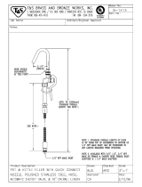
CONNECTING A RIGID VALVE DRAIN TUBE
To adapt a copper drain tube to the softener, use
a hacksaw to cut the barbed end from the drain
fitting as shown. Rotate the drain fitting so the
cutting blade clears the valve housing to prevent
damage to valve. Bug a compression fitting (1/4"
female pipe thread x 1/2" O.D. tube) and needed
tubing from gour local hardware store.
1/4" NPT
threads
!
_'t_i,,,_ / Barbs 1/2" O.D. copper
Cli_:-_€'p / tube (not provided)
Cut barbs from
drain fitting
Compression fitting
1/4" NPT x 1/2" O.D.
tube (not provided)
[_ INSTALL THE BRINE TANK
OVERFLOW FITTINGS AND HOSE
• Insert the rubber grommet into the 3/4" diameter
hole in the brine tank sidewall as shown.
• Push the end of the hose adapter elbow into the
grommet as shown.
• Attach a length of hose (use remaining hose from
Step 4) to the hose adapter elbow. Use a hose
clamp to hold it in place.
• Locate the other end of the hose at the drain
point. DO NOT ELEVATEthis hose higher than the
elbow on the brine tank.
IMPORTANT: DO NOT TEE OVERFLOW HOSE TO
VALVE DRAIN HOSE.
NOTE: This drain is for safetg onlg, If the cabinet
(brine tank) should over-fill with water, the excess is
carried to the drain.
\/
Grommet
Overflow ---_
drain hose
Hose
adapter
,.___i Hose
clamp
Do not connect
to valve drain
hose.
To acceptable
_, drain
8

Installation Instructions
16] INSTALL GROUNDING CLAMP
-ADANGER: Failure to properly attach
ground clamp could result in electrical shock.
If plumbing is metal, to maintain electrical ground
continuity in the house cold water piping, install the
included ground clamp as shown.
• Clean pipe with emery paper in the area where
the clamp is to be installed.
Install grounding clamps as shown, making sure
clamps fit freely around pipe.
Make sure lock washer is in place.
Handtighten screw, then one more full turn with
screwdriver.
NOTE: When replacing an existing softener, also
replace grounding clamps. If removing softener
completely, hard-plumb the water line with same
type of pipes as the original to assure plumbing
integrity and ground continuity over the life of
the home.
Ground
clamp
To valve inlet
From valve
outlet
_1 FLUSH PIPES, EXPEL AIR FROM
SOFTENER AND TEST YOUR
INSTALLATION FOR WATER LEAKS
-ACAUTION: Toavoidwateror air
pressure damage to softener inner parts, be
sure to do the following steps in exact order.
• Fully open 2 cold soft water faucets nearby
the softener.
• Place bypass valve in "bypass" position by
pushing the stem inward.
• Fully open the house main water pipe shutoff
valve. Observe a steady flow from both faucets
opened above.
_1 FLUSH PIPES, EXPEL AIR FROM
SOFTENER AND TEST YOUR
INSTALLATION FOR WATER
LEAKS ICONT.)
• Place bypass valve in the "service" position
EXACTLY as follows. KEEP SOFT WATER FAUCETS
OPEN.
SLOWLY pull or slide the valve stem (out) toward
the service position, pausing several times to
allow the softener to pressurize slowly.
After about 3 minutes, open a HOT water faucet
for 1 minute, or until all air is expelled, then
close. NOTE: If water appears cloudy or has salty
taste, allow to run for several more minutes, or
until clear.
• Close all water faucets.
Check your plumbing work for leaks and fix
right away if any are found. Be sure to observe
previous caution notes.
Turn on the gas or electric supply to the water
heater. Light the pilot, if applicable.
I_ ADD WATER AND SALT TO THE
BRINE TANK
• Lift the salt hole cover. Add about 3 gallons of
water into the tank. Do not add into the brinewell.
Fill tank with NUGGET, PELLETor coarse SOLAR
water softener salt with a purity of 99.5% or
higher. Do not use rock, block, granulated and ice
cream-making salts, or salt with iron-removing
additives (except for Diamond Crystal ®Red•Out ®
brand salt). Maximum salt storage capacity is
approximately 200 Ibs. Keep the salt hole cover
closed unless servicing the unit or refilling
with salt.
NOTE: If the softener is installed in a humid
basement or other damp area, it is better to fill the
tank with less salt, more frequently. Eighty to 100
Ibs. of salt will last for several months, depending on
water hardness, family size and water softening
system model.

Installation Instructions
[9] CONNECT TO ELECTRICAL POWER
To gain access to the transformer/power cord
assemblg, remove the salt hole cover from the
softener. Unclip the tabs on the rear of the top cover
and rotate the cover upward to remove. DO NOT
PULL OR DISCONNECT WIRING.
• The softener works on 2/4volt-60Hz electric
power. The included transformer changes
standard !20-volt AC house power to 2/4volts.
Plug the transformer into a 120-volt outlet onlg.
Be sure the outlet is alwags live so it can not be
switched off bg mistake.
+ Replace the top coven
+ Replace the salt hole cover.
PROGRAMMING THE CONTROL
PROGRAMMING THE CONTROL
/f_ smor+w__ bUuPtt(_n)
Display__ ([:_ DOWN (-)
.[:i:,] - .SELECT
L f _______ button
TOUCH or HOLD button
CONTROL SETTINGS REQUIRED upon installation
and after an extended power outage.
NOTES:
• WHEN THE TRANSFORHER IS PLUGGED INTO
THE ELECTRICALOUTLET, 12:00 PH (flashing), and
PRESENT TIME is displaued. Program the control
as instructed below.
If FT- - - or .... is flashing, use the UP •
button to set the correct model code as follows:
FT20 for GXSS20H. If you pass by the correct code
number, use the DOWN • button. Then press the
SELECT button to accept the correct model.
• A "beep" sounds while pressing buttons for
control programming. One beep signals a change
in the control display. Repeated beeps mean the
control will not accept a change from the button
you have pressed, and you should select another
button.
• To program the control, you will use the UP •,
DOWN • and SELECT buttons.
• Use the SELECT button to select the desired
control function.
SET PRESENT TIME OF DAY
1. Press the SELECT button until
PRESENTTIME appears in the
display.
2. Press UP • or DOWN • button
to set. The UP button advances
the time; the DOWN button
moves the time in reverse.
I U.CO _
.......................................................
I I ,._,,_A+
!.30
PRESENT TIME
If the present time is between noon and midnight,
be sure PM shows in the display. If the present
time is between midnight and noon, be sure AM
shows in the display.
NOTE: Each press of an UP • or DOWN • button
changes the time by one minute. Holding the button
changes the time at a rapid rate.
3. When the present time is correct, press SELECT to
accept.
10
SET WATER HARDNESS NUMBER
1. Press the SELECT button until
HARDNESS appears in the
display.
2. Press UP • or DOWN • button
to set your water hardness number in the
display. DOWN decreases the hardness value.
UP increases the hardness value.
NOTE: Each press of a button changes the display
by 1, between 1 and 25. Above 25, the display
changes 5 at a time (25, 30, 35, etc.). Holding a
button in changes the numbers at a rapid rate.

Installation Instructions
SET WATER HARDNESS NUMBER (CONT.)
3. When the displag shows gour water hardness
(in grains per gallon), press SELECT to accept.
NOTE: If there is clear water iron in your water
supply, you will need to increase the hardness
setting by 5 for each 1 ppm of clear water iron
in your water supply.
You can get the grains per gallon (gpg}
hardness of gour water supply from a water
analysis laboratory. If you are on a municipal
supply, call your local water department. Or
call Legend Technical Services, an independent
laboratory, to request a water hardness test kit
at 1.800.949.8220, option 4. If your report shows
hardness in parts per million (ppm} or milligrams
per liter (mg/I), simply divide by 17.1 to get the
equivalent number of grains per gallon.
SET NUMBER OF PEOPLE
1. Press the SELECT button until PEOPLE appears in
the display.
2. PresstheUP, orDOWN" [ ...._1 ]
buttons to set the number of _7
people living in your home.
The number of people determines
how often the water softener will regenerate. The
softener assumes that each person will use 70
gallons of water per day. If you set the number of
people to 4, then the softener assumes you will use
280 gallons per day. If you need more or less than
this, adjust the number of people accordinglg.
SET RECHARGE (STARTING} TiME
1. Press the SELECT button until
RECHARGE TIME appears in the
display.
NOTE: A flashing 2:00 AM (factorg
default) should show in the displag. This is a good
time for recharge to start (takes about 2 hours) in
most households because water is not in use. HARD
WATER is bgpassed to house faucets during
recharge.
If no change is needed, go to step 3. To change the
recharge starting time, follow step 2.
2. Press UP • or DOWN • button to set the desired
recharge start time. Be sure to observe the AM or
PM as gou did when setting the time of dag.
NOTE: Each press of a button changes the time bg
! hour. Holding the buttons in changes the time at
a rapid rate.
3. Press the SELECT button to accept.
SET DAYS BETWEEN RECHARGE
This feature is not used on this [ -( I _m ( ]
model. If you see this screen, your _7.0 i-i _-J
[ 1
hardness level has been turned off.
Go back to Set Water Hardness
Number section to set your water hardness level to
the hardness of your water supplg.
11

Installation Instructions
SANITIZING PROCEDURES
To complete the installation, do the following
sanitizing procedures.
Care is taken at the factorg to keep gour water
softener clean and sanitarg. Materials used to make
the softener will not infect or contaminate gour water
supplg and will not cause bacteria to form or grow.
However, during shipping, storage, installation and
operation, bacteria could get into the softener. For
this reason, sanitizing as follows is suggested when
installing.
NOTE: Sanitizing is recommended bg the
Water Quality Association for disinfecting.
1. Be sure to complete all installation steps, including
programming the control.
2. Pour about 3/4 oz. (1V2tablespoons) of common
5.25% unscented household bleach (Clorox, Linco,
Bo Peep, White Sail, Eagle, etc.) into the brinewell.
Refer to illustration on page 5.
3. IMPORTANT: Press and hold for 5 seconds
the faceplote TOUCH or HOLD button to start an
immediate recharge. The bleach will be drawn
through the water softener, and out the drain.
This process takes upproximatelg 2 hours.
4. If, after sanitization, water from the house
faucet tastes sultg or has u slight color, this is a
preservative from the resin tank. Turn on the cold
soft water faucets and drain for a few minutes or
until clear.
NOTE: When the sanitizing recharge is over, all
remaining bleach is flushed from the conditioner
and gour house COLD water supplg is fullg soft
immediatelg. However, gour water heater is filled
with hard water and as hot water is used, it will refill
with soft water. When all the hard water is replaced
in the water heater, hot onlg and mixed hot and cold
water will be fullg soft. If gou want totallg soft water
immediatelg, after the above recharge, drain the
water heater until the water runs cold.
WARN ING: ,fgoudodrainthewater
heater, use extreme care as the hot water could
cause burns. Turn the water heater off prior to
draining.
SPECIFICATIONS/DIMENSIONS
Rated Capacitg*
Amount of high capacitg resin (Ibs/cu. ft)
Resin tank nominal size (in., dia. x height)
Service flow rate (gpm)
Water supplg maximum hardness (gpg)
Water supplg maximum clear water iron (ppm)**
Water pressure limits (min.-max. psi)***
Pressure drop at rated service flow (psig)
Water temperature limits (min-max °F)
Water supplg minimum flow rate (gpm)
Maximum flow rate to drain (gpm)
G×SS20H
7,800 grains with
1.8 Ibs. of salt
16,800 grains with
5.8 Ibs. of salt
20,000 grains with
9.7 Ibs. of salt
31.7/0.61
8x40
6.5
50
6
20-125
9
40-120
3
2.0
INLET-OUTLET
_-11-1/2'4-
_- -- 3-3/8"
IT
40-1/2"
This sgstem conforms to NSE/ANS144 for the specific copocitg claims as verified and substantiated bg test data
* Testing was performed using pellet grade sodium chloride as the regeneront salt
** Extent of iron removal mog vorg with conditions The copocitg to reduce clear water iron is substantiated
bg independent Ioborotorg test data, State of Wisconsin requires additional treatment if water supplg
contains greater than Sppm clear water iron Use of Diamond CrgstoP Red,Out _ or Super Iron Out ®
will improve iron removal Refer to Cleaning Iron Out of the Water Softening Sgstem section
*** Canada working pressure limits: 1.4-70 kg/cm 2
12

About the water softener system, ge.com
Service
When the water softening system is providing
soft water, it is called "Service." During service,
hard water flows from the house main water pipe
into the water softening system. Inside the water
softening system resin tank is a bed made up of
thousands of tiny, plastic resin beads. As hard
water passes through the bed, each bead
attracts and holds the hard minerals. This is
called ion-exchanging. It is much like a magnet
attracting and holding metals. Water without
hard minerals (soft water) flows from the water
softening system and to the house pipes.
After a period of time, the resin beads become
coated with hard minerals and theg have to be
cleaned. This cleaning is called recharge.
Recharge is started at 2:00 AH (factory setting)
by the water softening system control, and
consists of five stages or cgcles. These are FILL,
BRINING, BRINE RINSE, BACKWASH and FAST
RINSE.
Automatic Hard Water Bgpass During Recharge
For emergencg needs, hard water is available
to the home during the recharge cgcles.
However, gou should avoid using HOT water
because the water heater will fill with the hard
water.
Fill
Salt dissolved in water is called brine. Brine is
needed to clean the hard minerals from resin
beads. To make the brine, water flows into the
salt storage area during the fill stage.
Brining
During brining, brine travels from the salt storage
area into the resin tank. Brine isthe cleaning
agent needed to remove hard minerals from the
resin beads. The hard minerals and brine are
discharged to the drain.
The nozzle and venturi create a suction to move
the brine, maintaining a very slow rate to get the
best resin cleaning with the least salt.
Brine Rinse
After a pre-measured amount of brine is used,
the brine valve closes. Water continues to flow in
the same path as during brining, except for the
discontinued brine flow. Hard minerals and brine
flush from the resin tank to the drain.
Backwash
During backwash, water travels up through
the resin tank at a fast flow rate, flushing
accumulated iron, dirt and sediments
from the resin bed and to the drain.
Fast Rinse
Backwash isfollowed by a fast flow of water
dawn through the resin tank. The fast flow
flushes brine from the bottom of the tank,
and packs the resin bed.
After fast rinse, the water softening system
returns to soft water service.
15

About the water softener system.
Breaking a Salt Bridge
Sometimes, a hard crust or salt bridge forms in
the salt storage area. It is usuallu caused bu high
humiditu or the wrong kind of salt. When the salt
bridges, an empt Uspace forms between the
water and salt. Then salt will not dissolve in the
water to make brine.
If the brine tank is full of salt, it is hard to tell
if Uou have a salt bridge. Salt is loose on top, but
the bridge is under it. The following is the best
wau to check for a salt bridge.
Salt should be loose all the wau to the bottom of
the tank. Take a broom handle or liketool, and
carefullu push it down into the salt, working it up
and down. If the tool strikes a hard object (be
sure it's not the bottom or sides of the tank), it's
most likelu a salt bridge. Carefullu break the
bridge with the tool. Do not pound on the walls
of the tank.
If the wrong kind of salt made the bridge, take it
out. Then fill the tank with nugget or pellet salt
only. In humid areas, it is best to fill with less salt,
more often to prevent a salt bridge from forming.
Pencil
mark
Broom
handle
Push tool into salt
bridge to break
I
\
Water level
bridge
14
Cleaning the Nozzle and Venturi Assembly
A clean nozzle and venturi is needed for the
water softening system to work properly. This
small unit makes the suction to move brine from
the salt storage area to the resin tank during
recharge. If it becomes plugged with sand, dirt,
etc., the water softening system will not work
and you will get hard water.
Toget to the nozzle and venturi, remove the
water softening system top cover Be sure the
water softening system is in service cycle (no
water pressure at nozzle and venturi). Then, while
holding the nozzle and venturi housing with one
hand, remove the cap. Lift out the screen support
and screen, then the nozzle and venturi. Wash
and rinse the parts in warm water until clean. If
needed, use a small brush to remove iron or dirt.
Also check and clean the gasket.
NOTE:Some models have a small flow plug
located in the nozzle and venturi, and/or a small
cone shaped screen in the housing. Be sure to
check and clean these parts, if your model is
so equipped.
Carefully replace all parts in the correct
order. Lightly lubricate the o-ring seal with clean
silicone grease or petroleum jelly and place in
position. Install and tighten the cap, by hand
only. Do not overtighten the cap.
Cap
O-ring seal "_*0
Screen -_-_ @
support
Screen
*Flow plug _
i
Nozzle &
Venturi
_.._ Screen
Gasket -_{ _j_/i_-
*Flow -_ _,
plug
Nozzle o
Venturi
housing
IMPORTANT: Be sure small holes in the gasket ore
centered directly over the small holes in the nozzle and
venturi housing.
*Install with numbered side up, concave side down.

About the face plate timer features, gecom
_4 i J- ]
3.-i 3 .M
RECHARGENOW
Recharging
If you have guests visiting, or other times
when you use more water than usual, you
could begin to run out of soft water. If the
softener is not scheduled to regenerate for
another day or two, you would get hard water
until then. If this happens, or you think it
might happen, press and hold in the TOUCH
or HOLD button for three seconds until
RECHARGENOW shows. RECHARGENOW
will flash in the display during the
regeneration, which lasts under 2 hours.
NOTE:Avoid using HOTwater while the
softener regenerates, because bypass hard
water will refill the water heater. Seethe
Automatic Bypass section.
I
nr
J-iL
l
Going on Vacation?
The day you leave on vacation, or for a long
absence, press (do not hold) the TOUCHor
HOLD button. VACbegins to flash in the
display. The timer will keep time, but the
softener will not regenerate.
NOTE:While on vacation, the softener will
go through a regeneration if the RECHARGE
NOWfeature is used.
To shut off the water supply to the softener,
use the plumbing bypass valve.
When you return, press the TOUCHor HOLD
button again to return the softener to service
and also return the softener to the correct
time of day in the display.
WARNING: nemen,bertodo
this or the softener will not regenerate
and _lOUwill soon have hard water
[
E-3
J
Error Code
An error code could appear in the face plate display if a problem occursin the softenerelectronics.
If you seean error codeinstead ofthe presenttime of day, seethe TroubleshootingTipssectionor call
the GEAnswer Center 800.626.2000for service.
What to Do When a Power Outage Occurs
If electrical power to the timer goes off, the
memory built into the timer circuitry keeps
all settings for six hours (minimum) or more.
The display is blank and softener will not
regenerate.
When electrical power comes on, one of two
things will happen.
m The present time of day will show,
Le_
meaning the timer memory has kept
all settings.
NOTE:If the softener was in a regeneration
when the power was lost, it will now finish
the cycle.
OR
[] The display will show a flashing time.
The timer memory did not keep the time
settings and they must be reset. See the
Programming the Control section.
You have to reset the present time only if the
display is flashing. The HARDNESS,NUMBEROF
PEOPLEand RECHARGETIMEnever require
resetting unless a change isdesired. Evenif the
clock isincorrect after a long power outage, the
softener works as it should to keep your water
soft. However, regenerations may occur at the
wrong time of the day until you reset the clock
to the correct time of day.
If the softener was in a regeneration when
the power went off, the valve will return to
service position without finishing the
regeneration cycle.
Ifyour water tastes salty:
- use RECHARGE NOW to start another
regeneration. See the Recharging section.
- open one or more soft water faucets and
allow to run until the salt taste is gone.
15

About the water softener system.
Service: Electronic Demand Time Features and Service
ERRORCODE
DISPLAYED ERR03 ERR04 ERR05
POSSIBLEDEFECT •Control
ERR01
• Motor
inoperative
• Wiring
harness or
connection
to switch
• Position
switch
• Control
ERR02
•Position
switch
•Control
•Motor
inoperative
or wiring
harness
•Control
•Position
switch or
wiring
harness
• Control
Toremove an error code: 1. Unplugtransformer.
Z Correctdefect.
& Plug transformer in.
4. Wait for at least 6 minutes. Theerror codewill return if the reasonfor
theerror code was not corrected.
Service: Timer/Softener, Service Checkout Procedure
If gou are not getting soft water, and an error
code is not displaced, usethe procedures below
to find the problem. First make the following
visual checks.
VISUAL CHECKS:
1.Is there electrical power to the outlet the water
softening sgstem transformer is plugged into?
Z Isthere sufficient salt in the storage tank?
3. Isthe softener bypass valve directing water
for soft water service?
4. Is the valve drain hose open to the drain,
not more than 8' above the softener, and
unobstructed? If hose is above 8', see
page 8, step 4.
tf bloudo not find a problem with the visual
checks, continue below.
CONTROL SHOWS
WRONG TIME AND
DAY,AND/OR IS
FLASHING.
CONTROL
DISPLAY
BLANK.
Checkelectrical
power to control
.._ (outlet,
transformer,
power cable,all
connections).
INO POWERI.__. REPAIRAS
NEEDED
"-_"C POWEROK--_- I CONTROL
DEFECTIVE
Electricalpower was IInvestigate reason for
off. Resetthe correct _ Ipower ass.
time of daM.
Domanual
diagnostics
to verifg
i proper
function.
CONTROL DISPLAY
SHOWS CORRECTTIME
AND DAYAND IS
STEADY.
Domanual
diagnostics.
16

ge.com
Service: Manually Initiated Electronics Diagnostics
1.To enter diagnostics, press and hold the
SELECTbutton until (000- -) showsin
the displag.
A The letter(P) and dash(es)indicate
POSITIONswitch operation. Theletter
appearing means the switch isclosed;
the dash means the switch isopen.
Usethe TOUCHORHOLD (RECHARGE
Turbine Sv_tches 1
Water Switch
Meter
(not included in
this model)
TONIGHT-RECHARGENOW) button to manually advance
the valve into eachcycle and checkcorrect switch
operation.
CORRECTSWITCH
DISPLAYS VALVECYCLESTATUS
Valvein service,fill,brining, backwash
or fast rinseposition.
Valverotating from one position to
another
While in this diagnostic screen,the following information is
available and mag be beneficial for various reasons.This
information isretained by the computer from the first time
electrical power isapplied to the control.
?_:Pressand hold the UPbutton to displagthe number
of dags this control hashad electrical power applied.
:;;;,Pressand hold the DOWN button to displag the number
of regenerations initiated bg this control since the SR
code number was entered.
2. Pressthe SELECTbutton and hold in
three seconds until a ServiceRating code _wjw wl! bw_
appearsin the displag. ! I C P_
For correct water softening system
operation, the model code must be FT20 for model
GXSS2OH.
Toreset the code, pressthe UPor DOWN button until the
correct number shows.
3. Pressthe SELECTbutton to return to the present time displag.
If the code was changed, make ALL thetimer settings.
NOTE:If the control is left in a diagnostic displag or a
flashing display when setting times or hardness,presenttime
automatically returns if a button isnot pressedwithin four
minutes.
17

About the water softener system.
Service: lanuallg Advance Regeneration Check
This check verifies proper operation of the valve
motor, brine tank fill, brine draw, regeneration
flow rotes and other controller functions. First,
make the initial checks and the Nlonuolly Initioted
Electronics Diognostics.
NOTE;The control displag must show a steadg
time (not flashing).
1. Pressthe TOUCHor HOLD button and hold in
for three seconds. RECHARGENOW begins to
flush us the water softening sgstem enters the 4.
fill cgcle of regeneration. Remove the brinewell
cover and, using a flashlight, observe fill water
entering the brine tank. If water does not enter
the tank, look for on obstructed nozzle,venturi,
fill flow plug or brine tubing. See Coreond
cleoning of the woter softening system section.
5.
2. After observing fill, press the TOUCHor HOLD
button to move the water softening sustem
into brining. A slow flow of wuter to the drain
will begin. Verifg brine draw from the brine
tank bu shining u flashlight into the brinewell
and observing u noticeuble drop in the liquid
level over an extended period of time.
NOTE:Be sure o salt bridge is not preventing
water from contacting salt. SeeCore ond
cleoning of the woter softening sgstem section.
If the woter softening sgstem does not drow
brine, check:
::Ji::nozzle and/or venturi dirtg or defective.
::Ji::nozzle and venturi not seated properlg
on gasket.
?_:restricted drain (check drain fitting and
hose).
!'!:_defective nozzle and venturi seal.
?_:other inner valve defect (rotor seal, rotor and
disc, wave washer, etc.).
NOTE:If water sgstem pressure is low, an
elevated drain hose mag cause back pressure,
stopping brine draw.
3. Again, press the TOUCHor HOLD button
to move the water softening system into
backwash. Look for a fast flow of water from
the drain hose. A slow flow indicates a plugged
top distributor, backwash flow plug or drain
hose.
Press the TOUCH or HOLD button to move the
water softening sgstem into fast rinse. Again
look for a fast drain flow. Allow the water
softening sgstem to rinse for a few minutes
to flush out ang brine that mag remain in
the resin tank from the brining cgcle test.
To return the water softening sgstem to
service, press the TOUCHor HOLD button.
18

Care and cleaning of the water softening system, geeom
Checking the Salt Storage Level and Refilling
Brine (salt dissolved in water)is needed for each
and every recharge. The water for making brine
is metered into the salt storage area bu the
water softening system valve and control.
However, gou must keep the tank supplied
with salt.
When to refill with salt: Check the salt level a
few weeks after Uouinstall the water softening
sustem and everu week after that. Refill when
the brine tank isfrom 1/3 to 1/2 full. In humid
areas it is best to fill with less salt more often.
Never allow the water softening sustem to use all
the salt before Uou refill it. Without salt, Uouwill
soon have hard waten
Use clean water softening salts onlU,at least
99.5% pure. NUGGET,PELLETor coarse SOLAR
salts are recommended. Do not use rock, block,
granulated or ice cream making salts. Theg
contain dirt and sediments, or mush and cake,
and will create maintenance problems.
CAUTION: Wotersoftening salt
with iron removing additives: Some salts
may have an additive to help the water
softening sustem handle iron in the water
supplu. Although this additive mau help to
keep the water softening sustem resin clean,
it may also release corrosive fumes that
weaken and shorten the life of some water
softening sustem parts. GE recommends
using only Diamond Crustal®Red,Out®
brand salt.
Cleaning Iron Out of the Water Softening Sgstem
Your water softening system takes hardness
minerals (calcium and magnesium) out of
the water. Also, it can control some (seethe
Specification Guidelines section) "clear water"
iron. With clear water iron, water from a faucet
is clear when first put into a glass. After 15 to 30
minutes, the water begins to cloud or turn rust
colored. A water softening sgstem will not
remove ang iron that makes the water cloudg
or rustg as it comes from the faucet (called red
water iron).To take red water iron out of water,
or over the maximum of clear water iron,
an iron filter or other equipment is needed.
GErecommends using only Diamond Crystal®
Red.Out ®brand salts with Iron Fighter®additive
to help keep the resin bed clean of clear iron. If
your water supply has clear water iron, periodic
resin bed cleaning is needed. GErecommends
using Super Iron Out®brand resin bed cleaner
to thoroughly clean your resin bed if your iron
content is high. Clean the bed at least every six
months, or more often if iron appears in the soft
water between cleanings.
IMPORTANT:It isimportant to mix the resin bed
cleaner with water (following the manufacturer's
instructions), pour it into the brinewell tube
(seepage 5) and recharge the softener
immediately. Do not pour the resin bed cleaner
in with the salt, as it will not be as effective in
cleaning the resin, and can cause damage to
the softener if it is left in the brine tank for an
extended period due to the corrosive gases
that are formed.
19

Before you call for service...
Troubleshooting Tips
Save time and money! Review the chart on the following
pages first and blou may not need to call for service.
NO SOFTWATER- Most Common Problems:
Check the following before coiling for service:
• Not enough saltishould be at least 1/3 full.
• Bypass valve in "Bypass" positioniknob should be in the "OUT" (service)position.
• Hardness setting too low. Check hardness setting and adjust. Verify hardness of supply
water--from local water company, water test or call the GEAnswer Center.
• Salt Bridgeisalt solidifies above water level so that brine water is not in contact with
salt. See the Breaking a Salt Bridge section.
Problem Possible Causes What To Do
No soft water Faucet or fixture where sample was •
taken not plumbed to soft water.
NOTE:Be sure sample is from a faucet
that does not mix soft and hard waten
For example, o single lever kitchen faucet,
if the cold side is plumbed to hard woten
Toconservesalt,the installermay haveisolatedsomefixtures
(outsidefaucets, toilets,etc.)from softwater.Fromthe outlet
of the water softening system, trace the water flow path,
in house plumbing. If soft water isnot directed to a faucet
or fixture where wanted,consult a plumber
Nosalt inthe brine tank or
salt bridged
• Refill with salt. See the Step-by-Step Installation Instructions.
Use the TOUCH or HOLD button to start o regeneration.
See the About the water softener system section.
Transformer unplugged at wall outlet or
power cableto softenernot connected.
Fuseblown or circuit breaker popped
on circuit to electrical outlet.
Electrical outlet on a circuit that can
continuously beswitched off
Checkfor a lossof electrical power to the water softening
system, due to any of theseconditions and correct asneeded.
With the power supply restored,observethe faceplate time
display and read Programming the Controlsection.
NOTE:Theelectricaloutlet forthesoftenershouldbe
livesoit cannot be accidentally switched off
Manual bypass valve in bypass position • Be surethe bypass valve stem ispositionedproperly, with the
knob in the OUTposition.Observeinstructions on the decal
at the end of the stem.
Valve drain hose pinched, plugged,
elevated too high or otherwise
restricted
• Any restriction inthis drain hosemay preventproper
operationofthe nozzle and venturi and reduce or prevent
brine draw during recharge.
Nozzleand venturi dirty, incorrectly
assembled or damaged
Referto CleaningtheNozzleand VenturiAssembly instructions.
With water pressureto the water softening system off,take the
nozzleassembly apart. Inspect,clean and replace asneeded.
Any foreign particle(s),scratches, nicks,etc.,in the passagescan
preventoperation.Besureholesin thegasketare centeredover
holesinthe housing.
Timer in the vacation (VAC)
position
• See VACATIONfeature to return the softener to service.
See the About the Face Plate Timer Features section,
20
/