Page is loading ...

Operating Instructions
Diesel engine
12 V 2000 M92
16 V 2000 M92
M015700/06E

Printed in Germany
© 2012 Copyright MTU Friedrichshafen GmbH
This Publication is protected by copyright and may not be used in any way whether in whole or in part without the prior
written permission of MTU Friedrichshafen GmbH. This restriction also applies to copyright, distribution, translation, micro‐
filming and storage or processing on electronic systems including data bases and online services.
This handbook is provided for use by maintenance and operating personnel in order to avoid malfunctions or damage
during operation.
Subject to alterations and amendments.

Table of Contents
1 Safety
1.1 General conditions 5
1.2 Personnel and organizational requirements 6
1.3 Transport 7
1.4 Safety regulations for startup and operation 8
1.5 Safety regulations for maintenance and
repair work 9
1.6 Auxiliary materials, fire prevention and
environmental protection 12
1.7 Conventions for safety instructions in the
text 15
2 General Information
2.1 Engine side and cylinder designations 16
2.2 Product description 17
2.3 Engine layout 23
2.4 Sensors, actuators and injectors –
Overview 25
3 Technical Data
3.1 12V 2000 M92 engine data 30
3.2 16V 2000 M92 engine data 33
3.3 Firing order 36
3.4 Engine – Main dimensions 37
4 Operation
4.1 Putting the engine into operation after
extended out-of-service periods (>3
months) 38
4.2 Engine – Putting into operation after
scheduled out-of-service-period 39
4.3 Tasks after extended out-of-service periods
(>3 weeks) 40
4.4 Checks prior to start-up 41
4.5 Fuel treatment system – Putting into
operation 42
4.6 Operational checks 44
4.7 Fuel treatment system – Switching on 45
4.8 Starting the engine 46
4.9 Stopping the engine 47
4.10 Emergency stop 48
4.11 After stopping the engine 49
4.12 Fuel treatment system – Shutdown 50
4.13 Plant cleaning 51
5 Maintenance
5.1 Maintenance task reference table [QL1] 52
6 Troubleshooting
6.1 Fuel treatment system – Troubleshooting 53
6.2 Troubleshooting 54
7 Task Description
7.1 SOLAS 57
7.1.1 SOLAS shielding as per MTN 5233 –
Installation 57
7.1.2 SOLAS shielding – Installation 58
7.1.3 Installation locations for SOLAS shielding 59
7.2 Engine 64
7.2.1 Engine – Barring manually 64
7.2.2 Engine – Barring with starting system 65
7.3 Cylinder Liner 66
7.3.1 Cylinder liner – Endoscopic examination 66
7.3.2 Cylinder liner – Instructions and comments on
endoscopic and visual examination 68
7.4 Crankcase Breather 70
7.4.1 Crankcase breather – Cleaning oil pre-
separator element 70
7.4.2 Crankcase breather – Oil separator
replacement, diaphragm check and
replacement 71
7.5 Valve Drive 73
7.5.1 Valve clearance – Check and adjustment 73
7.5.2 Cylinder-head cover – Removal and
installation 76
7.6 Injection Valve / Injector 77
7.6.1 Injector – Replacement 77
7.6.2 Injector – Removal and installation 78
7.7 Fuel System 80
7.7.1 Fuel system – Venting 80
7.8 Fuel Filter 81
7.8.1 Fuel filter – Replacement 81
7.8.2 Fuel prefilter – Differential pressure check and
adjustment of gauge 83
7.8.3 Fuel prefilter – Draining 84
M015700/06E 2012-06 | Table of Contents | 3
DCL-ID: 0000007582 - 006

7.8.4 Fuel prefilter – Flushing 85
7.8.5 Fuel prefilter – Filter element replacement 87
7.9 Charge-Air Cooling 89
7.9.1 Intercooler – Checking condensate drain line
for coolant discharge and obstruction 89
7.10 Air Filter 90
7.10.1 Air filter – Replacement 90
7.10.2 Air filter – Removal and installation 91
7.11 Air Intake 92
7.11.1 Contamination indicator – Signal ring position
check (optional) 92
7.12 Starting Equipment 93
7.12.1 Starter – Condition check 93
7.13 Lube Oil System, Lube Oil Circuit 94
7.13.1 Engine oil – Level check 94
7.13.2 Engine oil – Change 95
7.14 Oil Filtration / Cooling 96
7.14.1 Engine oil filter – Replacement 96
7.14.2 Centrifugal oil filter – Cleaning and filter-
sleeve replacement 98
7.15 Coolant Circuit, General, High-
Temperature Circuit 101
7.15.1 Drain and venting points 101
7.15.2 Engine coolant – Level check 106
7.15.3 Engine coolant – Change 107
7.15.4 Engine coolant – Draining 108
7.15.5 Engine coolant – Filling 109
7.15.6 HT coolant pump — Relief bore check 110
7.15.7 Engine coolant – Sample extraction and
analysis 111
7.15.8 Coolant filter – Replacement 112
7.16 Raw Water Pump with Connections 113
7.16.1 Raw water pump – Relief bore check 113
7.17 Belt Drive 114
7.17.1 Drive belt – Condition check 114
7.18 Battery-Charging Generator 115
7.18.1 Battery-charging generator drive – Drive belt
replacement 115
7.19 Fuel Supply System 116
7.19.1 Water drain valve – Check 116
7.19.2 Differential pressure gauge – Check 117
7.19.3 Water level probe (3-in-1 rod electrode) –
Check 118
7.19.4 Pump capacity – Check 119
7.19.5 Coalescer filter element – Replacement 120
7.20 Wiring (General) for Engine/Gearbox/Unit 122
7.20.1 Engine wiring – Check 122
7.21 Accessories for (Electronic) Engine
Governor / Control System 123
7.21.1 Engine governor and connectors – Cleaning 123
7.21.2 Engine governor – Checking plug-in
connections 124
7.21.3 EMU – Checking plug-in connections 125
7.21.4 Engine governor – Carry out self-test 126
7.21.5 EMU and connectors – Cleaning 127
7.21.6 ECU 7 engine governor – Removal and
installation 128
7.21.7 Engine monitoring unit – Removal and
installation 129
8 Appendix A
8.1 Abbreviations 130
8.2 MTU contacts/service partners 133
9 Appendix B
9.1 Special Tools 134
9.2 Index 140
4 | Table of Contents | M015700/06E 2012-06
DCL-ID: 0000007582 - 006

1 Safety
1.1 General conditions
General
In addition to the instructions in this publication, the applicable country-specific legislation and other com‐
pulsory regulations regarding accident prevention and environmental protection must be observed. This
state-of-the-art engine has been designed to meet all applicable laws and regulations. The engine may
nevertheless present a risk of injury or damage in the following cases:
• Incorrect use
• Operation, maintenance and repair by unqualified personnel
• Modifications or conversions
• Noncompliance with the Safety Instructions
Correct use
The engine is intended solely for use in accordance with contractual agreements and the purpose envis‐
aged for it on delivery. Any other use is considered improper use. The engine manufacturer accepts no
liability whatsoever for resultant damage or injury in such case. The responsibility is borne by the user
alone.
Correct use also includes observation of and compliance with the maintenance specifications.
Modifications or conversions
Unauthorized modifications to the engine represent a safety risk.
MTU will accept no liability or warranty claims for any damage caused by unauthorized modifications or
conversions.
Spare parts
Only genuine MTU spare parts must be used to replace components or assemblies. MTU accepts no
liability whatsoever for damage or injury resulting from the use of other spare parts and the warranty shall
be voided in such case.
Reworking components
Repair or engine overhaul must be carried out in workshops authorized by MTU.
M015700/06E 2012-06 | Safety | 5
TIM-ID: 0000000860 - 017

1.2 Personnel and organizational requirements
Personnel requirements
All work on the engine shall be carried out by trained and qualified personnel only.
The specified legal minimum age must be observed.
The operator must specify the responsibilities of the operating, maintenance and repair personnel.
Organizational measures
This publication must be issued to all personnel involved in operation, maintenance, repair or transporta‐
tion.
Keep it at hand at the operating site of the engine so that it is available to operating, maintenance, repair
and transport personnel at all times.
Use the manual as a basis for instructing personnel on engine operation and repair with an emphasis on
explaining safety-relevant instructions.
This is particularly important in the case of personnel who only occasionally perform work on or around
the engine. This personnel must be instructed repeatedly.
For the identification and layout of the spare parts during maintenance or repair work, take photos or use
the spare parts catalog.
Working clothes and protective equipment
Wear proper protective clothing for all work.
Use the necessary protective equipment for the given work to be done.
6 | Safety | M015700/06E 2012-06
TIM-ID: 0000000874 - 018

1.3 Transport
Transport
Only use the lifting eyes provided to lift the engine.
Only use transport and lifting devices approved by MTU.
Take the engine's center of gravity into account.
The engine must only be transported in installation position, max. permissible diagonal pull 10°.
If the engine is supplied with special aluminum foil packing, lift the engine at the lifting eyes of the bear‐
ing pedestal or use a means of transportation which is appropriate for the given weight (forklift truck).
Install the crankshaft locking device and the locking screws for the engine mounts prior to engine trans‐
portation.
Secure the engine against tilting during transport. In particular when going down inclines or ramps, the
engine must be secured against moving and tilting.
Setting the engine down after transport
Only set down engine on a firm, level surface.
Make sure that the consistency and load-bearing capacity of the ground or support surface is adequate.
Never set an engine down on the oil pan unless expressively authorized to do so by MTU on a case-to-
case basis.
M015700/06E 2012-06 | Safety | 7
TIM-ID: 0000002614 - 003

1.4 Safety regulations for startup and operation
Safety precautions when putting the equipment into operation
Prior to initial operation of the assembly or plant, install the assembly or unit according to the specifica‐
tions and check the installation according to the MTU specifications.
Before putting the device or plant into operation, always ensure:
• that all maintenance and repair work is completed,
• that all loose parts have been removed from rotating machine components,
• that all persons are clear of the danger zone of moving machine components.
Immediately after putting the device or plant into operation, make sure that all control and display instru‐
ments as well as the monitoring, signaling and alarm systems are working properly.
Safety regulations for equipment operation
Emergency procedures must be practiced regularly.
The operator must be familiar with the controls and displays.
The operator must be familiar with the consequences of all operations to be performed.
During operation, the display instruments and monitoring units must be permanently observed with re‐
gard to present operating status, violation of limit values and warning or alarm messages.
The following steps must be taken if a malfunction of the system is recognized or reported by the system:
• inform supervisor(s) in charge,
• analyze the message,
• if required, carry out emergency operations e.g. emergency engine stop.
Engine operation
The following conditions must be fulfilled before starting the engine:
• Wear ear protectors.
• Ensure that the engine room is well ventilated.
• Do not inhale engine exhaust gases.
• Ensure that the exhaust system is free of leaks and that the gases are discharged to atmosphere.
• Mop up any leaked or spilled fluids and lubricants immediately or soak up with a suitable binding
agent.
• Protect battery terminals, battery-charger terminals and cables against accidental contact.
• When the engine is running, never release coolant, oil, fuel, compressed-air or hydraulic lines.
Operation of electrical equipment
When operating electrical equipment, certain components of this equipment are live.
Observe the safety instructions for these devices.
8 | Safety | M015700/06E 2012-06
TIM-ID: 0000023743 - 010

1.5 Safety regulations for maintenance and repair work
Safety regulations for maintenance and repair work
Have maintenance and repair work carried out by qualified and authorized personnel only.
Allow the engine to cool down before starting maintenance work (risk of explosion of oil vapors).
Before starting work, relieve pressure in systems and compressed-air lines which are to be opened.
Take special care when removing ventilation or plug screws from the engine. Cover the screw or plug
with a rag to prevent fluids escaping under pressure.
Take special care when draining hot fluids ⇒ Risk of injury.
When changing the engine oil or working on the fuel system, ensure that the engine room is adequately
ventilated.
Allow the engine / system to cool down before starting to work.
Observe the maintenance and repair instructions.
Never carry out maintenance and repair work with the engine running unless expressly instructed to do
so.
Secure the engine against accidental starting.
Disconnect the battery when electrical starters are fitted.
Close the main valve on the compressed-air system and vent the compressed-air line when pneumatic
starters are fitted.
Disconnect the control equipment from the assembly or system.
Use only proper, calibrated tools. Observe the specified tightening torques during assembly/disassembly.
Carry out work only on assembles and/or units which are properly secured.
Never use lines for climbing.
Keep fuel injection lines and connections clean.
Always seal connections with caps or covers if a line is removed or opened.
Take care not to damage lines, in particular fuel lines, during maintenance and repair work.
Ensure that all retainers and dampers are installed correctly.
Ensure that all fuel injection and pressurized oil lines are installed with enough clearance to prevent con‐
tact with other components. Do not place fuel or oil lines near hot components.
Do not touch elastomeric seals if they have carbonized or resinous appearance unless hands are proper‐
ly protected.
Note cooling time for components which are heated for installation or removal ⇒ Risk of burning.
When working high on the engine, always use suitable ladders and work platforms. Make sure compo‐
nents are placed on stable surfaces.
Observe special cleanness when conducting maintenance and repair work on the assembly or system.
After completion of maintenance and repair work, make sure that no loose objects are in/on the assem‐
bly or system.
Before barring the engine, make sure that nobody is standing in the danger zone. Check that all guards
have been reinstalled and that all tools and loose parts have been removed after working on the engine.
The following additional instructions apply to starters with beryllium copper pinion:
• Breathing protection of filter class P2 must be applied during maintenance work to avoid health haz‐
ards caused by the beryllium-containing pinion. Do not blow out the interior of the flywheel housing or
the starter with compressed air. Clean the flywheel housing inside with a class H dust extraction de‐
vice as an additional measure.
M015700/06E 2012-06 | Safety | 9
TIM-ID: 0000000879 - 023

Welding work
Never carry out welding work on the assembly, system, or engine-mounted units. Cover the engine when
welding in its vicinity.
Do not use the assembly or system as ground terminal.
Do not route the welding lead over or near the wiring harnesses of MTU systems. The welding current
may otherwise induce an interference voltage in the wiring harnesses which could conceivably damage
the electrical system.
Remove parts (e.g. exhaust pipes) which are to be welded from the engine beforehand.
Hydraulic installation and removal
Check the function and safe operating condition of tools and fixtures to be used. Use only the specified
devices for hydraulic removal/installation procedures.
Observe the max. permissible push-on pressure specified for the equipment.
Do not attempt to bend or apply force to lines.
Before starting work, pay attention to the following:
• Vent the hydraulic installation/removal tool, the pumps and the lines at the relevant points for the
equipment to be used (e.g. open vent plugs, pump until bubble-free air emerges, close vent plugs).
• For hydraulic installation, screw on the tool with the piston retracted.
• For hydraulic removal, screw on the tool with the piston extended.
For a hydraulic installation/removal tool with central expansion pressure supply, screw spindle into shaft
end until correct sealing is established.
During hydraulic installation and removal, ensure that nobody is standing in the immediate vicinity of the
component to be installed/removed.
Working on electrical/electronic assemblies
Always obtain the permission of the person in charge before commencing maintenance and repair work
or switching off any part of the electronic system required to do so.
De-energize the appropriate areas prior to working on assemblies.
Do not damage cabling during removal work. When reinstalling ensure that wiring is not damaged during
operation by contact with sharp objects, by rubbing against other components or by a hot surface.
Do not secure cables on lines carrying fluids.
Do not use cable binders to secure cables.
Always use connector pliers to tighten connectors.
Subject the device or system to a function check on completion of all repair work.
Store spare parts properly prior to replacement, i.e. protect them against moisture in particular. Pack de‐
fective electronic components and assemblies in a suitable manner when dispatched for repair, i.e. par‐
ticularly protected against moisture and impact and wrapped in antistatic foil if necessary.
Working with laser equipment
When working with laser equipment, always wear special laser-protection goggles ⇒ Heavily focused ra‐
diation.
Laser equipment must be fitted with the protective devices necessary for safe operation according to
type and application.
10 | Safety | M015700/06E 2012-06
TIM-ID: 0000000879 - 023

For conducting light-beam procedures and measurement work, only the following laser devices must be
used:
• Laser devices of classes 1, 2 or 3A.
• Laser devices of class 3B, which have maximum output in the visible wavelength range (400 to 700
nm), a maximum output of 5 mW, and in which the beam axis and surface are designed to prevent
any risk to the eyes.
M015700/06E 2012-06 | Safety | 11
TIM-ID: 0000000879 - 023

1.6 Auxiliary materials, fire prevention and environmental
protection
Fire prevention
Rectify any fuel or oil leaks immediately; even quantities of oil or fuel on hot components can cause fires
– therefore always keep the engine in a clean condition. Do not leave cloths soaking with fluids and lubri‐
cants on the engine. Do not store combustible materials near the engine.
Do not weld pipes and components carrying oil or fuel. Before welding, clean with a nonflammable fluid.
When starting the engine with an external power source, connect the ground lead last and remove it first.
To avoid sparks in the vicinity of the battery, connect the ground lead from the external power source to
the ground lead of the engine or to the ground terminal of the starter.
Always have a suitable extinguishing agent (fire extinguisher) on hand and familiarize yourself fully with
its handling.
SOLAS classification
On engines/plants with SOLAS classification, operational checks must include the following tasks:
• Check all covers (fitted in accordance with SOLAS requirements) on lube oil and fuel pipe connections
(>1.8 bar) for damage, replace as necessary. (→ Page 17)
Noise
Noise can lead to an increased risk of accidents if acoustic signals, warning shouts or sounds indicating
danger are drowned.
In all work areas with a sound pressure level in excess of 85 dB (A), wear ear protection (cotton wool,
ear plug or capsules).
Environmental protection
Modification or removal of mechanical or electronic components or the installation of additional compo‐
nents as well as the execution of calibration processes that might affect the emission characteristics of
the engine are prohibited by emission regulations. Emission control units/systems may only be main‐
tained, exchanged or repaired if the components used for this purpose are approved by MTU or equiva‐
lent components. Noncompliance with these guidelines might represent a violation of the Clean Air Act
and could involve the termination of the operating license by the emission authorities. MTU does not ac‐
cept any liability for violations of the emission regulations. MTU will provide assistance and advice if
emission-relevant components are intended to be modified. The MTU Maintenance Schedules ensure
the reliability and performance of MTU engines and must be complied with over the entire life cycle of the
engine.
Only fuels of the specified quality required to achieve emission limits must be used.
In Germany, the VAwS (=regulations governing the use of plants that may affect water quality) is applica‐
ble, which means work must only be carried out by authorized specialist companies (MTU is an author‐
ized specialist company).
Dispose of used fluids, lubricants and filters in accordance with local regulations.
Auxiliary materials
Use only fluids and lubricants that have been tested and approved by MTU.
Fluids and lubricants must be kept in suitable, properly designated containers. When using fluids, lubri‐
cants and other chemical substances, follow the safety instructions that apply to the product. Take spe‐
cial care when using hot, chilled or caustic materials. When using flammable materials, avoid all sparks
and do not smoke.
12 | Safety | M015700/06E 2012-06
TIM-ID: 0000002828 - 005

Lead
• When working with lead or lead-containing compounds, avoid direct contact to the skin and do not
inhale lead vapors.
• Prevent the buildup of white powder of lead.
• Switch on fume extraction system.
• After coming into contact with lead or lead-containing materials, wash your hands!
Acids and alkaline solutions
• When working with acids and alkalis, wear protective goggles or face mask, gloves and protective
clothing.
• If such solutions are spilled onto clothing, remove the affected clothing immediately!
• Rinse injured parts of the body thoroughly with clean water!
• Rinse eyes immediately with eyedrops or clean mains water!
Paints, enamels and varnishes
• When carrying out painting work outside the spray stands provided with fume extraction systems, en‐
sure that the area is well ventilated. Make sure that neighboring work areas are not impaired.
• No open flames!
• No smoking!
• Observe all fire-prevention regulations!
• Always wear a mask providing protection against paint and solvent vapors!
Liquid nitrogen
• Store liquid nitrogen only in small quantities and always in specified containers without fixed covers.
• Avoid body contact (eyes, hands). Contact of this nature would cause frostbite and numbing.
• Wear protective clothing, protective gloves, closed shoes and protective goggles / safety mask!
• Make sure that working area is well ventilated. Suffocation will result at 88% contamination of breath‐
ing air with nitrogen.
• Take great care not to subject containers, fittings and tools to impact or shock.
Compressed air
Compressed air is air compressed at excess pressure and is stored in tanks from which it can be extract‐
ed.
The pressure at which the air is kept can be read off at pressure gauges which must be connected to the
compressed air tanks and the compressed air lines.
When working with compressed air, safety precautions must be constantly observed:
• Pay special attention to the pressure level in the compressed air network and pressure vessel!
• Connecting devices and equipment must either be assembled for this pressure, or, if the permitted
pressure for the connecting elements is lower than the pressure required, a pressure reducing valve
and safety valve (set to permitted pressure) must form an intermediate connection. Hose couplings
and connections must be securely attached!
• Always wear protective goggles when blowing off tools or extracting chips!
• The snout of the air nozzle is provided with a protective disk (e.g. rubber disk), which prevents air‐
borne particles being reflected and thereby prevents injury to eyes.
• First shut off compressed air lines before compressed air equipment is disconnected from the supply
line, or before equipment or tool is to be replaced!
• Unauthorized use of compressed air, e.g. forcing flammable liquids (danger class AI, AII and B) out of
containers, results in a risk of explosion!
• Forcing compressed air into thin-walled containers (e.g. sheet metal, plastic, glass) for drying purpos‐
es or to check for leaks will result in a risk of bursting!
• Blowing dirt from soiled clothes while still worn is prohibited!
M015700/06E 2012-06 | Safety | 13
TIM-ID: 0000002828 - 005

Used oil
Used oil may contain harmful combustion residues.
Rub your hands with skin protection cream!Wash your hands after contact with used oil.
14 | Safety | M015700/06E 2012-06
TIM-ID: 0000002828 - 005

1.7 Conventions for safety instructions in the text
DANGER
In the event of immediate danger.
Consequences: Death or serious injury
• Remedial action
WARNING
In the event of potentially dangerous situations.
Consequences: Death or serious injury
• Remedial action
CAUTION
In the event of dangerous situations.
Consequences: Minor injury or material damage
• Remedial action
NOTICE
In the event of a situation involving potentially adverse effects on the product.
Consequences: Material damage.
• Remedial action
• Additional product information
Note: This manual contains highlighted safety warnings in accordance with the US ANSI Z535 standard which
begin with one of the signal words listed above depending on the severity of the hazard.
Safety instructions
1. Read and familiarize yourself with all safety notices before starting up or repairing the product.
2. Pass on all safety instructions to your operating, maintenance, repair and transport personnel.
M015700/06E 2012-06 | Safety | 15
TIM-ID: 0000000881 - 018

2 General Information
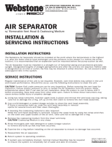
2.1 Engine side and cylinder designations
Engine sides are always designated as viewed from the driving end (KS).
The cylinders of the left engine side are designated "A" and those of the right side "B" (as per DIN ISO
1204). The cylinders of each bank are numbered consecutively, starting with No. 1 at the driving end.
Other components are numbered in the same way, i.e. starting with No. 1 on driving end.
1 Left engine side
2 KGS = Free end
3 Right engine side
4 KS = Driving end
16 | General Information | M015700/06E 2012-06
TIM-ID: 0000002185 - 010

2.2 Product description
Description of the engine
Engine
The engine is a liquid-cooled four-stroke diesel engine with c.c.w. direction of rotation, direct injection,
sequential turbocharging and charge-air cooling.
An electronic management system provides engine control and monitoring.
Fuel system with common rail injection
Controlled by the engine electronics, the common rail injection system determines injection pressure, in‐
jection timing and injection quantity independently of the engine speed.
Injection pressures up to 1800 bar ensure optimum fuel injection and combustion conditions.
Charging system
The charging system comprises charge-air system, exhaust system and sequential turbocharging.
The exhaust system is equipped with triple-walled, water-cooled exhaust lines.
The triple-walled design permits
• low surface temperature,
• reduced thermal load,
• absolute gas-tightness.
Lube oil system
Wet-sump forced-feed lubrication system
Components supplied with oil:
• Bearings
• Piston cooling
• Control and actuating elements of the sequential turbocharging system
Cooling system
• Two separate cooling circuits:
• Engine coolant
• Raw water
• Coolant cooling by raw water-cooled plate-core heat exchanger
• Thermostat-controlled coolant system
• Coolant-cooled / preheated charge air
• Coolant-cooled fuel return
Electronic system
Electronic control and monitoring system with integrated security and test system with interfaces to re‐
mote control system (RCS) and to monitoring system (MCS).
Electronic engine control unit (ECU)
Closed-loop control:
• Engine speed
• Fuel HP
M015700/06E 2012-06 | General Information | 17
TIM-ID: 0000002177 - 002

Open-loop control:
• Injection (fuel pressure, injection timing, injection duration, operating status)
• Sequential turbocharging (cutting-in and out) with secondary turbocharger
• Engine protection with multi-stage safety systems:
• Power reduction
• Power limitation
• Emergency stop
Monitoring:
• Exhaust gas temperature, A-side
• Exhaust temperature, B-side
• Engine speed
• Oil pressure
• Differential oil pressure
• Coolant temperature
• Coolant level
• Exhaust turbocharger speed
• Leak fuel level
• Oil temperature
• Coolant pressure
• Fuel pressure after filter
Monitoring in engine room
Engine control and monitoring unit (LOP)
Functions:
• Engine speed, oil pressure and coolant temperature are monitored and displayed
• Integrated safety system
• Integrated test system
• Redundant CAN bus interface to governor and higher-level control and monitoring system
• 24 V DC power supply
18 | General Information | M015700/06E 2012-06
TIM-ID: 0000002177 - 002

SOLAS – Fire protection specifications
Special connections
In case of leakage, the above-mentioned connection types are spray-protected even without a cover and
have been confirmed compliant with SOLAS by GL and DNV.
Plug-in pipe connection
The sleeve (4) covers the joint to prevent lateral spray.
Only leak-off along the line is possible, the pressure is decreased significantly if an O-ring (3) defect oc‐
curs.
The connection is confirmed as compliant with SOLAS by DNV and GL.
Plugs and sensors
Screw-in plugs (2) are sealed toward the outside either with a copper sealing ring (1), according to DIN,
or an O-ring (ISO).
In case of a loose single-ended union or a defective sealing ring (2), the liquid first has to pass the
thread.
M015700/06E 2012-06 | General Information | 19
TIM-ID: 0000002177 - 002

The pressure is so greatly reduced by this and the faulty sealing ring (2) that any leakage is not under
pressure.
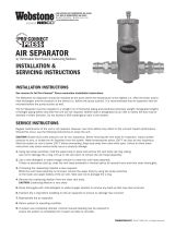
HP line between fuel injector and HP accumulator
1 Support ring
2 V-ring
3 Thrust ring
4 Union nut
5 HP line
6 Thrust screw
7 Thrust ring
8 V-ring
9 Support ring
20 | General Information | M015700/06E 2012-06
TIM-ID: 0000002177 - 002
/