
Electric Central Heating Flow Boiler
EKCO.LN2M
EKCO.L2M
Assembly and operating manual

This appliance is not intended for use by persons (including
children) with reduced physical, sensory or mental capabilities
or lack of experience and knowledge, unless they have been
given supervision or instruction concerning use of the appliance
by a person responsible for their safety. Children should be
supervised to ensure that they do not play with the appliance.
Used product can’t be treated as general communal waste. Disassembled appliance has
to be delivered to the collection point of electrical and electronic equipment for recycling.
Appropriate utilisation of used product prevents potential negative environmental inuences
that may occur as a result of inappropriate handling of waste.
In order to get more detailed information about recycling this product you should contact
the local government unit, waste management service or the shop where this product has
been purchased.

3
GB-096B_f.
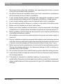
Safety instructions
1. Read and strictly follow the installation and operating instructions to ensure
a long life and reliable boiler operation.
2. An efcient electrical installation which has been completed in accordance
with the binding norms of electric installation.
3. A wet central heating system equipped with appropriate expansion vessel
made according to binding norms of hydraulic installation- closed system.
4. A wet central heating system must be ushed before boiler installation.
5. Do not install any barrier ttings (e.g. valves) on the outlet of the safety valve.
6. Boiler must be installed on an even wall surface.
7. Boiler must not be installed in a humid place, in a place exposed to the danger
of explosion or in a place where the ambient temperature may drop below 0°C.
8. Boiler installation and all electrical and hydraulic work must be performed by
a qualied professional installer.
9. All installation work must be performed when the power and water supply is
turned off.
10. Electric installation should be equipped with residual current protective devices
and other solutions which will ensure disconnecting the heater from the source
of power (intervals between all their poles should not be less than 3 mm).
11. Boiler is pre-set by the manufacturer to work with the central heating system.
Change the factory settings in the advanced settings to shift to boiler's co-
operation with DHW Cylinder.
12. Do not drain the water from central heating system after the heating season.
13. Leave the controller in stand-by mode and do not cut off power supply between
the heating seasons.
14. If the boiler is intended for underoor heating it is necessary to:
- install safety tting that protects against exceeding current ow temperature,
- adjust suitable maximum ow temperature for given CH installation (advanced
settings).

4
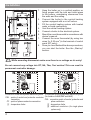
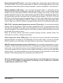
Installation
1. Hang the boiler up in a vertical position on
xing screws with the inlet and outlet pipes
to the bottom, maintaining clearances from
the walls and the ceiling.
2. Connect the boiler to the central heating
system equipped with a cut-off valves.
3. Fill the central heating system with treated
water or liquid nonfreezing.
4. Vent the central heating system.
5. Connect a boiler to the electrical system.
6. Mount the room thermostat in accordance with
device's manual.
7. Connect the room thermostat (by using two
wires 2 x 0,35 mm
2
) to the terminal of control
panel (RT entry).
8. Once you have nished the above procedures,
you can start the boiler. See the „Start-up”
section.
While mounting thermostat make sure there is no voltage on its entry!
Do not connect any voltage into RT, NA, Thw, Text entries! This can result in
permanent controller damage.
!
N
L
1
2
N
L
1
Connection to the three-phase electrical system.
PNL - points of neutral and protective conductor
connection
PF - points of phase conductors connection
[1] - temperature limiter
Connection to the single phase electrical system
(for boilers of 4kW,6kW and 8kW)
PNL - connection points of neutral, protective and
phase conductors
[1] - temperature limiter
[2] - additional conductors (for single phase
system only)
inlet outlet

5
GB-096B_f.
1
Thw
Text
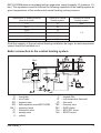
Boiler connection to the central heating system
EKCO.LN2M boilers are equipped with an expansion vessel (capacity: 6l, pressure: 1,5
bar). The expansion vessel is sufcient for following capacities of the heating system at
given temperatures of the medium and central heating system pressure.
Shall the capacity of the wet central heating installation be larger, an extra expansion
vessel should be installed on it.
Temperature of heating medium
(feed and return)
Capacity of central
heating system
Pressure in central
heating system
[°C] [l] [bar]
85/70 58
1,5
70/55 79
55/45 103
50/40 115
45/35 128
PI - manometer
ZK - cut-off valve
RW - expansion pipe
NW - built-in expansion vessel (EKCO.LN2M)
NW 1 - expansion vessel
ZT - thermostatic valve
ZP - passage valve
G - radiator
F - magnetic lter
RT - room temperature thermostat
ZS - drain valve
TWV - three-way valve
ZAS - DHW Cylinder
Thw - WE-019/01 sensor
Text - WE-027 sensor

6
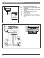
Connection of external appliances
E
T
hw
F
T
ext
PUMP TWV
Regulator
pokojowy
T
hw
T
ext
TWV - connection point of three-way valve
Thw - connection point of water temp. sensor
(in cylinder)
NA - master appliance connection point ( factory
shorted)
RT - room thermostat connection point
C - master appliance
D - room thermostat
E - KOSPEL WE-027 outside temp. sensor
F - KOSPEL WE-019/01 cylinder's water temp.
sensor
Room
thermostat

7
GB-096B_f.
Room thermostat (RT entry) – when the voltage free contact gets opened the boiler
will stop heating. The entry is responsible for boiler's control depending on the room
temperature (room thermostat connection details – section 'Installation ', sub clause 7).
Master appliance (NA entry) – you can limit the power used, i.e. the boiler can be
switched off while another appliance consumes electricity. To do it, an electrician should
install in line an extra open contact to the NA entry (voltage free entry), so that when
a master appliance gets on, the contact will be opened the boiler switched off. When the
NA contact gets opened, heating will get off and the pump stopped. The EKCO.LN2 and
EKCO.L2 model may also work as second boiler. If it is so, the master boiler by opening
the NA entry will stop heating of EKCO. However, the mode of the three-way valve
control stays on so a DHW cylinder is charged by the heat from the different heat source.
WE-019/01 cylinder water temperature sensor (Thw entry) - for connection details
please, refer to the gure. If there is need to extend the wire- it is necessary to make
it as short as possible. If the wire is too long there may occur disturbances and it may
not work properly. The wires should not run close to mains cables and they must not
go around other electric wires.
Note! To activate sensor and DHW cylinder heating function, please follow the
instructions in section „Advanced settings”.
Three way divert valve (TWV entry) - the valve has to be connected in accordance
with the diagram on page 18-19 depending on the model. Note: in order to activate
DHW function one must follow the instructions in the section 'Advanced settings'.
WE-027 outside temperature sensor (Text entry) - for connection details please, refer to
the gure. If there is need to extend the wire- it is necessary to make it as short as possible.
If the wire is too long there may occur disturbances and it may not work properly.
The wires should not run close to mains cables and they must not go around other
electric wires. It is recommended to mount the sensor on the northern or north-west
facade of the building away from windows and exhaust fans.
Note! If outside temperature sensor hasn't been connected then it is necessary
to switch off weather compesation (heating curve coefcient, weather
compensation switch off > C=0 )

8
Start up
1. Check if required pressure has been reached within the installation (see section
"Technical Data"). In order to check it use or button when control panel
is „on’’.
Flashing A symbol (see section "Failures") indicates too low installation pressure.
Above description does not apply to open type installations.
2. Set the pump at constant mode (see section "Advanced settings”).
3. Switch the boiler on (press button).
4.
Check if the appropriate medium ow rate has been reached (the „H” indicator is
on with a constant light). The pump should get vented itself after a short working
time, however, if necessary, vent the pump in the following way:
• close the cut-off valve on the outlet,
• set the pump on the highest efciency
(see section "Advanced settings”)
,
• let the boiler with the pump on run for 15-30 s.
• open the cut off valve.
5. Switch the boiler off (press and hold button for 3 seconds).
6. Set the pump at automatic mode (see section "Advanced settings”).
7. Connect programmed room thermostat.
8. Switch the boiler on (press button).
9. Set parameters of heating curve adjusted to the building (heating curve coefcient
and offset) - see section "Advanced settings".
Reset of the curve slope switches off weather compensation and starts boiler's
operation in accordance with manual adjustments of the installation.

9
GB-096B_f.
Advanced settings
For advanced settings switch the control panel to stand-by mode (press and hold button
for approximately 3 seconds) then press and hold button , and for a short period
of time press and let go.
To select parameter press to change the value press or :
- boiler power - enter rated power (kW) as indicated on identication label,
- pump's working mode:
• PA- automatic,
• PC- constant.
- pump's efciency [E]:
• E3.0 - 3.0m,
• E4.0 - 4.0m,
• E5.0 - 5.0m,
• E5.0 - 5.0m,
• E7.0 - 7.0m,
• E7.5 - 7,5m.
- pumpe press mode [PPn]:
• constant pressure difference (pressure indicator- on),
• variable pressure difference (pressure indicator- ushing).
- number of active heaters [AH].
- DHW cylinder function [DHW function start up]:
• 0- off,
• 1- on,
- maximal temperature of CH installation,
- heating curve coefcient, weather compensation switch off:
• C = 4 - 25,
• C = 0 - weather compensation switched off, manual regulation of installation's
temperature.
- heating curve offset:
• o = -9°C ÷ 9°C.

10
• outside temperature of CH switch off: setting outside temperature above which
CH circuit is switched off,
• pressure sensor in CH installation,
- active (1),
- inactive (0), sensor should be deactivated in open type installations
• work time counter of boiler (read-only). Counter displays digits (without preceding
zeros) from the most signicant one with 0,5 sec breaks- after the display of the
least signicant digit, display is blanked for 2 sec.
To exit advanced settings and save all changes press and hold button
.
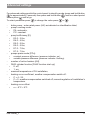
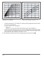
Heating curve coefcient. Offset of the heating curve for c=12
c=4
20,0
30,0
40,0
50,0
60,0
70,0
80,0
90,0
-20-1001020
˚C
˚C
c=6
c=8
c=10
c=12
c=14
c=16
c=18
c=20
c=22
c=24
o = +9
c = 12 o = 0
o = -9
20,0
30,0
40,0
50,0
60,0
70,0
80,0
90,0
-20-1001020
˚C
˚C

11
GB-096B_f.
kW
O
C
l/min.
bar
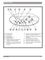
Control panel
A - pressure [bar]
B - ow [l/min]
C - power [kW]
D - temperature [°C]
E - digital display
F - indicator of medium temperature
setting (for DHW cylinder)
G - indicator of room thermostat
and heating activity (for central
heating)
H - indicator of pump and ow activity
I - indicator of data transmission
J - indicator of weather compensation
controller
K - inlet temperature indicator
L - outlet temperature indicator
M - indicator of boiler activity (CH)
N - indicator of boiler activity (DHW)
O - control buttons

12
Stand-by mode
In the stand-by mode the pump is activated everyday for 2 min, which prevents its
blockage. Control panel is blanked- only F indicator ashes. To switch stand-by mode
press and hold for 3 sec
button.
Note! Do not cut off power supply in-between heating seasons. Pressing
or
buttons displays parameter of installation's pressure. After 1 min of inactivity the
display becomes blanked again. Pressing button in the stand-by mode shifts
boiler's operation to winter or summer mode depending on the valid settings adjusted
before activation of stand-by mode.
Winter mode (CH)
Winter mode is activated when icon
is on.
In winter mode control panel displays pictograms that describe current boiler's
operation mode- digital display indicates heating medium's temperature.
Pressing
button shifts to preview of current parameters and settings of boiler's
operation in the following order:
- CH medium temperature adjustment (indicators D and M on), indicator J is on when
weather compensation regulator is active (advanced settings). Indicator J ashes
when there is no possibility to determine installation's temperature due to the lack or
failure of outside sensor- the boiler shifts to manual adjustments. Pressing
or
buttons when heating medium temperature is indicated on the display results in heating
medium value change. Note, it works only when weather compensation regulator is
switched off (advanced settings - parameter C=0) or when there is no outside sensor,
- inlet temperature (indicators D and K on),
- outlet temperature (indicators D and L on),
- outside temperature (indicators D and G on),
- ow of the medium through the boiler (indicator B on),
- pressure in CH installation (indicator A on),
- activated power (indicator C on).
If the buttons are not used for 1 minute the display returns to general view mode.
Pressing
button during preview or adjustment of parameters results in immediate
return to display's general view mode.
Optimal adjustment of heating medium temperature in accordance with outside
temperature parameters and building's parameters results in low exploitation costs
(reduced power consumption).

13
GB-096B_f.
Winter mode CH + DHW (winter mode option and co-operation with DHW
cylinder)
In this mode the three-way valve directs the medium to either central heating installation
or cylinder coil. The priority is to heat the DWH cylinder, at the same time the central
heating system is off.
In CH + DHW icons and . are on. In this mode control panel displays
pictograms that describe current boiler's operation mode- digital display indicates
heating medium's temperature.
Pressing
button shifts to preview of current parameters and settings of boiler's
operation in the following order:
- CH medium temperature adjustment (indicators D and M on), indicator J is on
when weather compensation regulator is active (advanced settings). Indicator J
ashes when there is no possibility to determine installation's temperature due
to the lack or failure of outside sensor- the boiler shifts to manual adjustments.
Pressing
or buttons when heating medium temperature is indicated on
the display results in heating medium value change. Note, it works only when
weather compensation regulator is switched off (advanced settings - parameter
C=0) or when there is no outside sensor.
- preview and adjustment of water temperature in DHW cylinder (indicators D and N
on). Water temperature in the cylinder is displayed only when WE-019/01 sensor
is plugged to entry Thw. Pressing
or buttons when water temperature in
cylinder is indicated on the display results in temperature adjustment- regulation
range: 30 - 80°C (indicators D, N, F on). Setting 0°C blocks boiler's heating on
DHW cylinder which is indicated by ashing icon ,
- inlet temperature (indicators D and K on),
- outlet temperature (indicators D and L on),
- outside temperature (indicators D and G on),
- ow of the medium through the boiler ( indicator B on),
- pressure in CH installation (indicator A on),
- activated power (indicator C on).
If the buttons are not used for 1 minute the display returns to general view mode.
Pressing
button during preview or adjustment of parameters results in immediate
return to display's general view mode.
Optimal adjustment of heating medium temperature in accordance with outside
temperature parameters and building's parameters results in low exploitation costs
(reduced power consumption).

14
Summer mode (only with active cylinder's function)
To switch to summer mode press (when in main view of winter mode). This mode
is available only if the boiler co-operates with the DHW cylinder. Heating medium is
directed to cylinder’s coil. When icon
is on and icon is off it shows that the
boiler operates in summer mode. In this mode control panel displays pictograms that
describe current boiler's operation mode- digital display indicates heating medium's
temperature.
Pressing button shifts to preview of current parameters and settings of boiler's
operation in the following order:
- preview and adjustment of water temperature in DHW cylinder (indicators D and N
on). Water temperature in the cylinder is displayed only when WE-019/01 sensor
is plugged to entry Thw. Pressing
or buttons when water temperature in
cylinder is indicated on the display results in temperature adjustment- regulation
range: 30 - 80°C (indicators D, N, F on). Setting 0°C blocks boiler's heating on
DHW cylinder which is indicated by ashing icon
,
- inlet temperature (indicators D and K on),
- outlet temperature (indicators D and L on),
- outside temperature (indicators D and G on),
- ow of the medium through the boiler ( indicator B on),
- pressure in CH installation (indicator A on),
- activated power (indicator C on).
If the buttons are not used for 1 minute the display returns to general view mode.
Pressing button during preview or adjustment of parameters results in immediate
return to display's general view mode.
Optimal adjustment of heating medium temperature in accordance with outside
temperature parameters and building's parameters results in low exploitation costs
(reduced power consumption).

15
GB-096B_f.
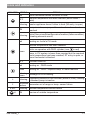
INDICATOR STATUS DETAILS
ON room thermostat allows the boiler to heat
OFF
required temperature has been reached (boiler doesn’t
heat)
flickering master appliance doesn’t allow to heat (NA entry is open)
ON
pump is active, a proper ow rate of medium has been
reached
ickering
lack of ow or insufcient ow rate of medium (failure condition),
a heating elements are off,
red heating on- boiler's CH mode
green
desired temperature has been reached
boiler co-operates with DHW cylinder (icon
in red)
temp. in CH system is lower than required but the required
room temperature has been reached, RT entry is open, or
room thermostat is blocked
OFF summer mode on
red heating on - DHW mode
green
heating on - DHW- required temp. of water reached
ickering
green
blockage of DHW heating
A
ickering
installation pressure is not sufcient (below 0,5 bar), heating
is blocked, pump is inactive
E
horizontal
dashes
parameter out of range or temp. sensor failure
K or L ickering relevant temperature sensor failure
+D
ON preview of outside temperature
Icons and indicators

16
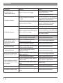
Symptom Reason Action
the indicators on
control panel are off
lack of boiler power supply
check parameters of power
network and fuses
contact authorised service
A indicator ickers
insufcient pressure (below
0,5 bar)
shift the controller to the pressure
view, increase pressure within the
installation to required level
pressure sensor failure
switch the controller to pressure
preview, if display E indicates "--"
contact authorised service
H indicator ickers
pump's blockage unblock pump's rotor
lack of medium's ow through the
boiler- boiler's blockage
an air-bound central heating system,
vent the installation, pump and boiler
check patency of CH installation
and clean the lter
failure of pump's power supply contact authorised service
failure of pump or ow sensor contact authorised service
G indicator is off (in
winter mode), room
thermostat indicates
heating on
failure of installation that con-
nects room thermostat
check connecting installation
failure of electronic module contact authorised service
K indicator ickers
failure of inlet temp. sensor, boiler
shifted to failure condition
contact authorised service
L indicator ickers
failure of outlet temp. sensor,
heating blockage
contact authorised service
G indicator ickers and
the boiler doesn't work
failure of installation that connects
master appliance
check connecting installation
failure of electronic module contact authorised service
EKCO.LN2M and EKCO.
L2M model doesn’t heat
the cylinder
failure of cylinder's temp. sensor
or thermostat
contact authorised service, replace
temp. sensor or thermostat
failure of three-way valve servo-
motor
replace rotor
failure of electronic module contact authorised service
J indicator ickers failure of external temp. sensor contact authorized service
N indicator ickers (red)
failure of cylinder water temp.
sensor
contact authorized service
Failures

17
GB-096B_f.
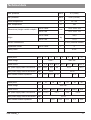
Technical data
Max. pressure
MPa
0,3 (3 bar)
Min. pressure
MPa
0,05 (0,5 bar)
Outlet temperature °C
20 ÷ 85
Max. temperature °C 100
Dimensions (height x width x depth)
EKCO.LN2M
mm
710 x 418 x 252
EKCO.L2M
710 x 418 x 153
Wight
EKCO.LN2M
kg
~24,5
EKCO.L2M
~17,2
Boiler's connections G 3/4" (internal thread)
Expansion vessel
EKCO.LN2M
l 6
Safety class IP 22
Rated power kW 4 6 8 4 6 8 12
Rated voltage 230V~ 400V 3N~
Rated current A 17,4 26,0 34,8 3x5,7 3x8,7 3x11,7 3x17,3
Min. power supply cable cross-section mm
2
3x2,5 3x4 3x6 5x1,5 5x2,5
Max. power supply cable cross-section mm
2
3 x 25 5 x 25
Max. allowed network impedance Ω 0,27 0,17 0,15 0,27
Rated power kW 15 18 21 24 30 36
Rated voltage 400V 3N~
Rated current A 3x21,7 3x26,0 3x30,3 3x34,6 3x43,3 3x52
Min. power supply cable cross-section mm
2
5 x 2,5 5 x 4 5 x 6 5 x 10
Max. power supply cable cross-section mm
2
5 x 25
Max. allowed network impedance Ω 0,27 0,22 0,13 0,11 0,09

18
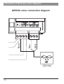
Connection of three-way valve- diagrams
AZV 642
PUMP
TWV
AZV642 valve connection diagram
Brown
Blue
Black

19
GB-096B_f.
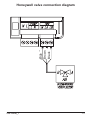
PUMP
TWV
Honeywell valve connection diagram
Brown
Blue
Black

-
 1
1
-
 2
2
-
 3
3
-
 4
4
-
 5
5
-
 6
6
-
 7
7
-
 8
8
-
 9
9
-
 10
10
-
 11
11
-
 12
12
-
 13
13
-
 14
14
-
 15
15
-
 16
16
-
 17
17
-
 18
18
-
 19
19
-
 20
20


Kospel EKCO.LN2M Assembly And Operating Manual
- Type
- Assembly And Operating Manual
- This manual is also suitable for
Ask a question and I''ll find the answer in the document
Finding information in a document is now easier with AI
Related papers
Other documents
-
Wolf FGB-K-28 Installation And Maintenance Instructions For Contractors
-
-
-
REMEHA Avanta Plus 35c Installation and Service Manual
-
-
Viessmann VITOLIGNO 300-H Series Operating Instructions Manual
-
elco THISION L PLUS Installer Guide
-
Wolf CGB-2 Series Installation Instructions For Contractors
-
Viessmann VITODENS 200 Installation Instructions Manual
-