SECO-LARM E-941SA-1200 Owner's manual
- Category
- Wall & ceiling mounts accessories
- Type
- Owner's manual
This manual is also suitable for
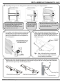
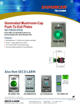
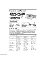
SECO-LARM E-941SA-1200 is electromagnetic lock designed for indoor use and is ideal for securing doors against unauthorized entry. When power is applied to the electromagnetic lock, it creates an extremely strong magnetic field, so the electromagnet is strongly attracted to the steel armature plate which is mounted on the secured door. Once the electromagnet is deactivated, the secured door will function normally without any residual magnetism.
SECO-LARM E-941SA-1200 is electromagnetic lock designed for indoor use and is ideal for securing doors against unauthorized entry. When power is applied to the electromagnetic lock, it creates an extremely strong magnetic field, so the electromagnet is strongly attracted to the steel armature plate which is mounted on the secured door. Once the electromagnet is deactivated, the secured door will function normally without any residual magnetism.


-
 1
1
-
 2
2
-
 3
3
-
 4
4
-
 5
5
-
 6
6
-
 7
7
-
 8
8


SECO-LARM E-941SA-1200 Owner's manual
- Category
- Wall & ceiling mounts accessories
- Type
- Owner's manual
- This manual is also suitable for
SECO-LARM E-941SA-1200 is electromagnetic lock designed for indoor use and is ideal for securing doors against unauthorized entry. When power is applied to the electromagnetic lock, it creates an extremely strong magnetic field, so the electromagnet is strongly attracted to the steel armature plate which is mounted on the secured door. Once the electromagnet is deactivated, the secured door will function normally without any residual magnetism.
Ask a question and I''ll find the answer in the document
Finding information in a document is now easier with AI
Related papers
-
 SECO-LARM USA Enforcer SD-7251GCEX1Q User manual
-
SECO-LARM E-941SA-1K5Q Owner's manual
-
SECO-LARM E-941SA-1K2PQ Owner's manual
-
-
-
SECO-LARM USA Enforcer E-942SA-600 User manual
-
 SECO-LARM USA E-941SA-1K2PD User manual
-
-
-


Other documents
-
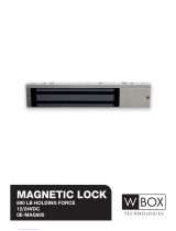 W Box Technologies 600 LB HOLDING FORCE Installation guide
-
 Visionis FPC-5640 One Door Access Control Outswinging Door 600lbs Maglock User guide
-
 Visionis FPC-5656 One Door Access Control Outswinging Door 1200lbs Maglock User guide
-
 SECO-LARM USA E-942SA-600 User manual
-
 SECO-LARM USA Door E-941DA-1K2P User manual
-
 ENFORCER E-941SA-80Q Installation guide
-
none 80012 Installation guide
-
Gianni Industries EM-NH300 Installation guide
-
Gianni Industries PH-450 Series Installation guide
-
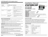
 ENFORCER E-941SA-400Q Installation guide


