
Table of Contents
Cover photo may show optional equipment
not supplied with standard unit.
Read the Operator’s Manual entirely. When you
see this symbol, the subsequent instructions and
warnings are serious - follow without exception.
Your life and the lives of others depend on it!
!
© Copyright 2015 Printed
R
C5615, RC6615, RCM5615, & RCM6615 S/N 944729-
Rotary Cutter
330-323M
26590
Operator’s Manual
4/20/15

Table of Contents
RC5615 & RC6615 (540 RPM) RCM5615 & RCM6615 (1000 RPM) Rotary Cutter 330-323M
4/20/15
© Copyright 2015 All rights Reserved
Land Pride provides this publication “as is” without warranty of any kind, either expressed or implied. While every precaution has been taken in the
preparation of this manual, Land Pride assumes no responsibility for errors or omissions. Neither is any liability assumed for damages resulting from the use
of the information contained herein. Land Pride reserves the right to revise and improve its products as it sees fit. This publication describes the state of this
product at the time of its publication, and may not reflect the product in the future.
Land Pride is a registered trademark.
All other brands and product names are trademarks or registered trademarks of their respective holders.
Printed in the United States of America.
Table of Contents
Important Safety Information . . . . . . . . . . . . . 1
Safety at All Times . . . . . . . . . . . . . . . . . . . . . . . . . 1
Look For The Safety Alert Symbol . . . . . . . . . . . . . 1
Safety Labels . . . . . . . . . . . . . . . . . . . . . . . . . . . . . 4
Introduction . . . . . . . . . . . . . . . . . . . . . . . . . . 10
Application . . . . . . . . . . . . . . . . . . . . . . . . . . . . . . 10
Using This Manual . . . . . . . . . . . . . . . . . . . . . . . . . 10
Owner Assistance . . . . . . . . . . . . . . . . . . . . . . . . . 10
Section 1: Assembly & Set-up . . . . . . . . . . . 11
Tractor Requirements . . . . . . . . . . . . . . . . . . . . . . 11
Horsepower . . . . . . . . . . . . . . . . . . . . . . . . . . . . 11
Drawbar Set-up . . . . . . . . . . . . . . . . . . . . . . . . . 11
PTO Speed . . . . . . . . . . . . . . . . . . . . . . . . . . . . 11
Hydraulic Outlets . . . . . . . . . . . . . . . . . . . . . . . . 11
Before You Start . . . . . . . . . . . . . . . . . . . . . . . . . . 11
Torque Requirements . . . . . . . . . . . . . . . . . . . . . . 11
Hitch Types . . . . . . . . . . . . . . . . . . . . . . . . . . . . . . 12
Standard Clevis Hitch . . . . . . . . . . . . . . . . . . . . . 12
Double Swivel Clevis Hitch (Optional) . . . . . . . . 12
Bar-Tite Hitch (Optional) . . . . . . . . . . . . . . . . . . 12
Ball Hitch (Optional) . . . . . . . . . . . . . . . . . . . . . . 12
Pintle Hitch (Optional) . . . . . . . . . . . . . . . . . . . . 12
Hitch Assembly . . . . . . . . . . . . . . . . . . . . . . . . . . . 13
Jack Assembly . . . . . . . . . . . . . . . . . . . . . . . . . . . 13
Standard Clevis Hitch Hook-up . . . . . . . . . . . . . . . 14
Double Swivel Clevis Hitch Hook-up . . . . . . . . . . . 15
Bar-Tite Hitch Hook-up . . . . . . . . . . . . . . . . . . . . . 16
Driveline Installation . . . . . . . . . . . . . . . . . . . . . . . 17
Hydraulic Hook-up . . . . . . . . . . . . . . . . . . . . . . . . . 17
Right & Left Wing Set-ups . . . . . . . . . . . . . . . . . . . 18
Purge Hydraulic System . . . . . . . . . . . . . . . . . . . . 19
Lift Cylinder Mounting Position . . . . . . . . . . . . . . . 19
Unhook Rotary Cutter . . . . . . . . . . . . . . . . . . . . . . 20
Section 2: Adjustments . . . . . . . . . . . . . . . . . 21
Leveling Center Deck & Wings . . . . . . . . . . . . . . . 21
Center Deck Leveling . . . . . . . . . . . . . . . . . . . . . 21
Wing Deck Leveling . . . . . . . . . . . . . . . . . . . . . . 22
Cutting Height Adjustment . . . . . . . . . . . . . . . . . . . 22
Section 3: Operating Instructions . . . . . . . . 23
Startup Checklist . . . . . . . . . . . . . . . . . . . . . . . . . . 23
Safety Information . . . . . . . . . . . . . . . . . . . . . . . . . 23
Tractor & Cutter Inspection . . . . . . . . . . . . . . . . . . 24
Blade Operation Inspection . . . . . . . . . . . . . . . . . . 25
Avoid Extreme Turning Angles . . . . . . . . . . . . . . . 25
Transport Locks . . . . . . . . . . . . . . . . . . . . . . . . . . 26
Transporting . . . . . . . . . . . . . . . . . . . . . . . . . . . . . 26
Field Set-up . . . . . . . . . . . . . . . . . . . . . . . . . . . . . . 27
Lower Wing Down & Set Cutting Height . . . . . . . 27
Set Wing Lift Lever In Float Position . . . . . . . . . 27
Select Gear Range . . . . . . . . . . . . . . . . . . . . . . . 27
Engage Blades . . . . . . . . . . . . . . . . . . . . . . . . . . 27
Disengage Blades . . . . . . . . . . . . . . . . . . . . . . . 27
General Operating Instructions . . . . . . . . . . . . . . . 28
Section 4: Options & Accessories . . . . . . . . 29
Safety Guard Options . . . . . . . . . . . . . . . . . . . . . . 29
Optional Low Lift Blades . . . . . . . . . . . . . . . . . . . . 29
Tire Options . . . . . . . . . . . . . . . . . . . . . . . . . . . . . . 29
Hitch Options . . . . . . . . . . . . . . . . . . . . . . . . . . . . . 29
Hydraulic Accessories . . . . . . . . . . . . . . . . . . . . . . 30
Hydraulic Wing Control Kit . . . . . . . . . . . . . . . . . 30
Selector Control Valve Kit . . . . . . . . . . . . . . . . . . 30
Mechanical Wing Lift . . . . . . . . . . . . . . . . . . . . . . . 31
Installation Instructions . . . . . . . . . . . . . . . . . . . . 31
Operating Instructions . . . . . . . . . . . . . . . . . . . . 31
Shredder/Fixed Blades & Baffle Kits . . . . . . . . . . . 32
Assembly Instructions . . . . . . . . . . . . . . . . . . . . . 32
EU Export Light Kit (Accessory) . . . . . . . . . . . . . . 36
Section 5: Maintenance & Lubrication . . . . . 37
General Maintenance Information . . . . . . . . . . . . . 37
Tractor Maintenance . . . . . . . . . . . . . . . . . . . . . . . 37
Cutter Blade Maintenance . . . . . . . . . . . . . . . . . . . 37
Drivelines With Slip Clutches . . . . . . . . . . . . . . . . . 39
Type A Clutches . . . . . . . . . . . . . . . . . . . . . . . . . 39
Type B Clutches . . . . . . . . . . . . . . . . . . . . . . . . . 41
Skid Shoes & Side Skirts . . . . . . . . . . . . . . . . . . . . 42
Center Skid Shoe . . . . . . . . . . . . . . . . . . . . . . . . 42
Wing Skid Shoe . . . . . . . . . . . . . . . . . . . . . . . . . 42
Side Skirts With Skid Shoe Attached . . . . . . . . . 42
Tire Maintenance . . . . . . . . . . . . . . . . . . . . . . . . . . 43
Turnbuckles . . . . . . . . . . . . . . . . . . . . . . . . . . . . . . 43
Long Term Storage . . . . . . . . . . . . . . . . . . . . . . . . 44
Ordering Replacement Parts . . . . . . . . . . . . . . . . . 44
Lubrication Points . . . . . . . . . . . . . . . . . . . . . . . . . 46
Axle Hub Bearing . . . . . . . . . . . . . . . . . . . . . . . . 46
Trailing Arm Pivots . . . . . . . . . . . . . . . . . . . . . . . 46
Axle Pivots . . . . . . . . . . . . . . . . . . . . . . . . . . . . . 47
Wing Hinge . . . . . . . . . . . . . . . . . . . . . . . . . . . . . 47
Adjustable Turnbuckle . . . . . . . . . . . . . . . . . . . . 47
Gearbox . . . . . . . . . . . . . . . . . . . . . . . . . . . . . . . 48
Divider Box . . . . . . . . . . . . . . . . . . . . . . . . . . . . . 48
Hitch Frame . . . . . . . . . . . . . . . . . . . . . . . . . . . . 49
Double Swivel Clevis Hitch . . . . . . . . . . . . . . . . . 49
Bar-Tite Hitch . . . . . . . . . . . . . . . . . . . . . . . . . . . 49
Intermediate Driveline Joints . . . . . . . . . . . . . . . 49
Wing Driveline Profile Tubes . . . . . . . . . . . . . . . 50
Wing Driveline Joints & Shields . . . . . . . . . . . . . 50
Conventional Driveline Profile Tubes . . . . . . . . . 51
Conventional Driveline Joints & Shields . . . . . . . 51
CV Main Driveline Profile Tubes . . . . . . . . . . . . . 52
CV Main Driveline Joints & Shields . . . . . . . . . . 52
Accessing CV Driveline Joints . . . . . . . . . . . . . 53
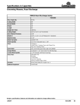
Section 6: Specifications & Capacities . . . . . 54
Section 7: Features & Benefits . . . . . . . . . . . 56
Section 8: Troubleshooting . . . . . . . . . . . . . . 57
Section 9: Torque & Tire Inflation Charts . . . 58
Section 10: Warranty . . . . . . . . . . . . . . . . . . . 59

1
Important Safety Information
4/20/15
RC5615 & RC6615 (540 RPM) RCM5615 & RCM6615 (1000 RPM) Rotary Cutter 330-323M
Table of Contents
Important Safety Information
These are common practices that may or may not be applicable to the products described in
this manual.
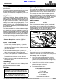
Safety at All Times
Thoroughly read and understand
the instructions given in this
manual before operation. Refer to
the “Safety Label” section, read all
instructions noted on them.
Do not allow anyone to operate
this equipment who has not fully
read and comprehended this
manual and who has not been
properly trained in the safe
operation of the equipment.
▲ The operator must not use drugs
or alcohol as they can change the
alertness or coordination of that
person while operating equipment.
The operator should, if taking over-
the-counter drugs, seek medical
advice on whether he/she can
safely operate the equipment.
▲ Operator should be familiar with all
functions of the unit.
▲ Operate controls from the driver’s
seat only. Never operate controls
from the ground.
▲ Make sure all guards and shields
are in place and secured before
operating implement.
▲ Keep all bystanders away from
equipment and work area.
▲ Do not leave tractor or implement
unattended with engine running.
▲ Dismounting from a moving tractor
can cause serious injury or death.
▲ Do not allow anyone to stand
between tractor and implement
while backing up to implement.
▲ Keep hands, feet, and clothing
away from power-driven parts.
▲ Watch out for fences, trees, rocks,
wires, etc., while operating and
transporting implement.
▲ Turning tractor too tight may cause
hitched machinery to ride up on
wheels. This could result in injury
or equipment damage.
Look For The Safety Alert Symbol
The SAFETY ALERT SYMBOL indicates there is a
potential hazard to personal safety involved and extra
safety precaution must be taken. When you see this
symbol, be alert and carefully read the message that
follows it. In addition to design and configuration of
equipment, hazard control, and accident prevention are
dependent upon the awareness, concern, prudence, and
proper training of personnel involved in the operation,
transport, maintenance, and storage of equipment.
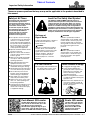
Parts Manual QR Locator
The QR (Quick Reference) code on the
cover and to the left will take you to the
Parts Manual for this equipment.
Download the appropriate App on your
smart phone, open the App, point your
phone on the QR code and take a picture.
Dealer QR Locator
The QR code on the left will
link you to available dealers
for Land Pride products.
Refer to Parts Manual QR
Locator on this page for
detailed instructions.
!
Be Aware of
Signal Words
A Signal word designates a degree or
level of hazard seriousness. The
signal words are:
Indicates an imminently hazardous
situation which, if not avoided, will
result in death or serious injury. This
signal word is limited to the most
extreme situations, typically for
machine components that, for
functional purposes, cannot be
guarded.
!
DANGER
Indicates a potentially hazardous
situation which, if not avoided, could
result in death or serious injury, and
includes hazards that are exposed
when guards are removed. It may also
be used to alert against unsafe
practices.
Indicates a potentially hazardous
situation which, if not avoided, may
result in minor or moderate injury. It
may also be used to alert against
unsafe practices.
!
WARNING
!
CAUTION
For Your Protection
▲ Thoroughly read and understand
the “Safety Label” section, read
all instructions noted on them.
Tractor Shutdown & Storage
▲ If engaged, disengage PTO.
▲ Lower attached implement to
ground, put tractor in park or set
park brake, turn off engine, and
remove switch key to prevent
unauthorized starting.
▲ Wait for all components to come to
a complete stop before leaving the
operator’s seat.
▲ Detach and store implement in an
area where children normally do
not play. Secure implement using
blocks and supports.
OFF
R
E
M
O
V
E

2
Important Safety Information
RC5615 & RC6615 (540 RPM) RCM5615 & RCM6615 (1000 RPM) Rotary Cutter 330-323M
4/20/15
Table of Contents
These are common practices that may or may not be applicable to the products described in
this manual.
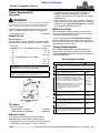
Use Safety
Lights and Devices
▲ Slow moving tractors,
self-propelled equipment, and
towed implements can create a
hazard when driven on public
roads. They are difficult to see,
especially at night.
▲ Flashing warning lights and turn
signals are recommended
whenever driving on public roads.
Use A Safety Chain
▲ A safety chain will help control
drawn machinery should it
separate from the tractor drawbar.
▲ Use a chain with the strength
rating equal to or greater than the
gross weight of the towed
machinery.
▲ Attach the chain to the tractor
drawbar support or other specified
anchor location. Allow only
enough slack in the chain to
permit turning.
▲ Do not use safety chain for towing.
▲ Maximum transport speed for an
attached implement is 20 mph. DO
NOT EXCEED. Never travel at a
speed which does not allow
adequate control of steering and
stopping. Some rough terrains
require a slower speed.
▲ As a guideline, use the following
maximum speed weight ratios for
an attached implement:
20 mph when weight of attached
implement is less than or equal to
the weight of machine towing the
implement.
10 mph when weight of attached
implement exceeds weight of
machine towing implement but
not more than double the weight.
▲ IMPORTANT: Do not tow a load
that is more than double the weight
of the machine towing the load.
Transport
Machinery Safely
▲ Comply with state and local laws.
▲ Use towing vehicle and trailer of
adequate size and capacity.
▲ Secure equipment towed on a
trailer with tie downs and chains.
▲ Sudden braking can cause a trailer
to swerve and upset. Reduce
speed if trailer is not equipped with
brakes.
▲ Avoid contact with any over head
utility lines or electrically charged
conductors.
▲ Engage park brake when stopped
on an incline.
Practice Safe Maintenance
▲ Understand procedure before doing
work. Use proper tools and
equipment, refer to Operator’s
Manual for additional information.
▲ Work in a clean dry area.
▲ Lower attached implement to the
ground, put tractor in park, turn off
engine, and remove key before
performing maintenance.
▲ Allow implement to cool completely
before working on it.
▲ Disconnect battery ground cable (-)
before servicing or adjusting
electrical systems or before welding
on implement.
▲ Do not grease or oil implement
while it is in operation.
▲ Inspect all parts. Make certain
parts are in good condition &
installed properly.
▲ Remove buildup of grease, oil, or
debris.
▲ Remove all tools and unused parts
from implement before operation.

3
Important Safety Information
4/20/15
RC5615 & RC6615 (540 RPM) RCM5615 & RCM6615 (1000 RPM) Rotary Cutter 330-323M
Table of Contents
These are common practices that may or may not be applicable to the products described in
this manual.
Wear
Protective Equipment
▲ Wear protective clothing and
equipment appropriate for the job.
Clothing should be snug fitting
without fringes and pull strings to
avoid entanglement with moving
parts.
▲ Prolonged exposure to loud noise
can cause hearing impairment or
hearing loss. Wear suitable
hearing protection such as
earmuffs or earplugs.
▲ Operating equipment safely
requires the operator’s full
attention. Avoid wearing radio
headphones while operating
machinery.
Prepare for Emergencies
▲ Be prepared if a fire starts.
▲ Keep a first aid kit and fire
extinguisher handy.
▲ Keep emergency numbers for
doctor, ambulance, hospital, and
fire department near phone.
911
Keep Riders Off
Machinery
▲ Never carry riders or use
machinery as a person lift.
▲ Riders obstruct operator’s view.
▲ Riders could be struck by foreign
objects or thrown from the
machine.
▲ Never allow children to operate
equipment.
Avoid High
Pressure Fluids Hazard
▲ Escaping fluid under pressure can
penetrate the skin causing serious
injury.
▲ Avoid the hazard by relieving
pressure before disconnecting
hydraulic lines or performing work
on the system.
▲ Make sure all hydraulic fluid
connections are tight and all
hydraulic hoses and lines are in
good condition before applying
pressure to the system.
▲ Use a piece of paper or
cardboard, NOT BODY PARTS, to
check for suspected leaks.
▲ Wear protective gloves and safety
glasses or goggles when working
with hydraulic systems.
▲ DO NOT DELAY. If an accident
occurs, see a doctor familiar with
this type of injury immediately. Any
fluid injected into the skin or eyes
must be treated within
a few hours or
gangrene may
result.
Use Seat Belt and ROPS
▲ Operate only tractors equipped
with Roll-Over Protective
Structure (ROPS) and seat belt.
▲ Fasten seat belt snugly and
securely to help protect against
serious injury or death from falling
and tractor overturn.
▲ Wearing protective equipment
such as safety shoes, safety
glasses, hard hat, and ear plugs is
highly recommended.
Tire Safety
▲ Tire changing can be dangerous
and should be preformed by
trained personnel using the
correct tools and equipment.
▲ When inflating tires, use a clip-on
chuck and extension hose long
enough to allow you to stand to
one side and NOT in front of or
over the tire assembly. Use a
safety cage if available.
▲ When removing and installing
wheels, use wheel handling
equipment adequate for the
weight involved.

4
Important Safety Information
RC5615 & RC6615 (540 RPM) RCM5615 & RCM6615 (1000 RPM) Rotary Cutter 330-323M
4/20/15
Table of Contents
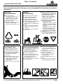
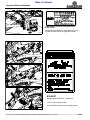
TRACTOR MUST HAVE SAFETY GUARDING
Safety Labels
Your Rotary Cutter comes equipped with all safety labels in
place. They were designed to help you safely operate your
implement. Read and follow their directions.
1. Keep all safety labels clean and legible.
2. Refer to this section for proper label placement. Replace
all damaged or missing labels. Order new labels from your
nearest Land Pride dealer. To find your nearest dealer,
visit our dealer locator at www.landpride.com.
3. Some new equipment installed during repair requires
safety labels to be affixed to the replaced component as
818-840C
Danger: Rollover Hazard (!-Place)
Located on left side of center deck
26592
26592
26592
818-130C
Caution! Use 540 rpm PTO only (RC Series Cutters)
818-240C
Caution! Use 1000 rpm PTO only (RCM Series Cutters)
818-276C
Warning! Rotating Blade Hazard (1-Place)
Located on left side of center deck
specified by Land Pride. When ordering new components
make sure the correct safety labels are included in the
request.
4. Refer to this section for proper label placement.
To install new labels:
a. Clean surface area where label is to be placed.
b. Spray soapy water onto the cleaned area.
c. Peel backing from label and press label firmly onto the
surface.
d. Squeeze out air bubbles with edge of a credit card or
with a similar type of straight edge.

5
Important Safety Information
4/20/15
RC5615 & RC6615 (540 RPM) RCM5615 & RCM6615 (1000 RPM) Rotary Cutter 330-323M
Table of Contents
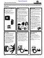
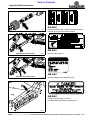
818-830C
Safety Combo (2-Places)
Located on the right and left wing decks
26593
818-543C
Danger! Guard Missing - DO NOT Operate (3-Places)
Located on center deck and both wing decks
26593
26592

6
Important Safety Information
RC5615 & RC6615 (540 RPM) RCM5615 & RCM6615 (1000 RPM) Rotary Cutter 330-323M
4/20/15
Table of Contents
818-564C
Danger! Rotating Blade (2-Places)
Located on the right and left wing decks
818-556C
Danger! Thrown Object Hazard (2-Places)
Located on the right and left wing decks
818-561C
Danger! Raised Wing Hazard (2-Places)
Located on the right and left wing decks
26593
26593
26593
26591
818-045C
Pinch Point Warning (1-Place)
Located on the back center axle

7
Important Safety Information
4/20/15
RC5615 & RC6615 (540 RPM) RCM5615 & RCM6615 (1000 RPM) Rotary Cutter 330-323M
Table of Contents
2659
26592
2660
2660
2659
818-229C
1 3/4" x 2 3/4" Amber Reflector
2- Places (Right and left wing locks)
2- Places (Right and left wings)
818-230C
1 11/16" x 2 13/16" Red Reflector (6-places)
2-places (Back side of wing cylinder mounts)
2-places (Back side of outside wheels spindles)
2-places (Back side of optional mechanical winch)
3022
838-614C
2" x 9" Red Reflector (2- places)
Located on back side of right and left wing axles
838-615C
2" x 9" Amber Reflector (1-Place)
Located on the front left face of the center deck

8
Important Safety Information
RC5615 & RC6615 (540 RPM) RCM5615 & RCM6615 (1000 RPM) Rotary Cutter 330-323M
4/20/15
Table of Contents
ROTATING DRIVELINE
KEEP AWAY!
818-552C
Danger! Rotating Driveline - Keep Away
1-Place (Top of splitter shield)
3-Places (Main driveline and 2-wing drivelines)
26593
26592
26592
26592
818-142C
Danger! Rotating Driveline - Keep Away (2-Places)
Located on right and left wing gearbox shields

9
Important Safety Information
4/20/15
RC5615 & RC6615 (540 RPM) RCM5615 & RCM6615 (1000 RPM) Rotary Cutter 330-323M
Table of Contents
838-588C
Warning: Folding Cutter Speed Warning
838-094C
Warning: High Pressure
848-088C
Danger: Guard Missing (2-Places)
Located behind replaceable wing side skirts
818-540C
Danger! Shield Missing - DO NOT Operate (3-Places)
Located on main and two wing drivelines
13313
Standard Clevis Hitch Shown
26592
Standard Clevis Hitch Shown
26592
24884

10
Introduction
RC5615 & RC6615 (540 RPM) RCM5615 & RCM6615 (1000 RPM) Rotary Cutter 330-323M
4/20/15
Table of Contents
Introduction
Owner Assistance
The Online Warranty Registration should be completed
by the dealer at the time of purchase. This information is
necessary to provide you with quality customer service.
The parts on your Rotary Cutter have been specially
designed by Land Pride and should only be replaced with
genuine Land Pride parts. Contact a Land Pride dealer if
customer service or repair parts are required. Your Land
Pride dealer has trained personnel, repair parts, and
equipment needed to service the implement.
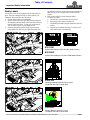
Serial Number
Model No. _____________Serial No. ______________
For quick reference and prompt service, record model
number and serial number in the spaces provided above
and again on warranty page 59. Always provide model
number and serial number when ordering parts and in all
correspondences with your Land Pride dealer. Refer to
Figure 1 for location of your serial number plate.
Serial Number Plate Location
Figure 1
Further Assistance
Your dealer wants you to be satisfied with your new
cutter. If for any reason you do not understand any part of
this manual or are not satisfied with the service received,
the following actions are suggested:
1. Discuss the matter with your dealership service
manager making sure that person is aware of any
problems you may have and has had the opportunity
to assist you.
2. If you are still not satisfied, seek out the owner or
general manager of the dealership, explain the
problem and request assistance.
3. For further assistance write to:
Land Pride Service Department
1525 East North Street
P.O. Box 5060
Salina, Ks. 67402-5060
E-mail address
lpservicedept@landpride.com
26597
Land Pride welcomes you to the growing family of new
product owners.
This Rotary Cutter has been designed with care and built
by skilled workers using quality materials. Proper
assembly, maintenance and safe operating practices will
help you get years of satisfactory use from this machine.
Application
The RC5615, RCM5615, RC6615 & RCM6615 Series
Rotary Cutters are designed and built by Land Pride to
provide excellent cutting performance on gently sloping
or slightly contoured right of-ways, roadsides, pastures,
set-aside-acres, or for residue in row crop fields. The 15'
cutting width, 2" to 14" cutting height and ability to cut
weeds and brush up to 4" in diameter (RC56 Series) and
4 1/2" diameter (RC66 Series) make them well suited for
these applications.
This Rotary Cutter utilizes a pull-type self-leveling clevis
hitch and Cat. 5 conventional or Cat. 6 constant velocity
main driveline for attachment to 50-250 HP tractors. The
RC Series attaches to 540 RPM tractors and RCM Series
attaches to 1000 RPM tractors. They are also offered with
various axle configurations and safety guard selections
making them an excellent choice for agricultural, state,
and municipal mowing applications.
See “Specifications & Capacities” on page 54 and
“Features & Benefits” on page 56 for additional
information and performance enhancing options.
Using This Manual
•
This Operator’s Manual is designed to help familiarize
you with safety, assembly, operation, adjustments,
troubleshooting, and maintenance. Read this manual
and follow the recommendations to help ensure safe
and efficient operation.
• The information contained within this manual was
current at the time of printing. Some parts may change
slightly to assure you of the best performance.
• To order a new Operator’s or Parts Manual, contact
your authorized dealer. Manuals can also be
downloaded, free-of-charge, from our website at
www.landpride.com.
• Store this manual in the dry storage tube located on top
of the splitter guard.
Terminology
“Right” or “Left” as used in this manual is determined by
facing forward in the direction the machine will operate
while in use unless otherwise stated.
Definitions
IMPORTANT: A special point of information related
to the following topic. Land Pride’s intention is this
information must be read & noted before continuing.
NOTE: A special point of information that the
operator should be aware of before continuing.

11
Section 1: Assembly & Set-up
4/20/15
RC5615 & RC6615 (540 RPM) RCM5615 & RCM6615 (1000 RPM) Rotary Cutter 330-323M
Table of Contents
Section 1: Assembly & Set-up
• Three duplex outlets are required if the wings are
folded up and down independently. (Requires
Hydraulic Wing Control Kit on page 30 to raise wings
independently.)
• If the tractor does not have the necessary number of
duplex outlets, there are control valve kits available to
add outlets. See “Hydraulic Accessories” on page 30
for a complete description of the kits.
Before You Start
Read and understand the operator’s manual for your
cutter. An understanding of how it works will aid in the
assembly and setup of your cutter.
It is best to go through the Pre-Assembly Checklist
before assembling the cutter. Speed up your assembly
task and make the job safer by having all needed parts
and equipment readily at hand.
Torque Requirements
See “Torque Values Chart” page 58 to determine
correct torque values when tightening hardware. See
“Tire Inflation Chart” at bottom of chart for exceptions to
common torque values.
Pre-Assembly Checklist
Check Reference
Have a fork lift or loader with properly sized chains and safety
stands capable of lifting and supporting the equipment on hand.
Have a minimum of two people available during assembly.
Make certain all major components and loose
parts are shipped with the machine.
Operator’s
Manual
Double check to make sure all parts, fasteners,
and pins are installed in the correct location.
Refer to the Parts Manual if unsure. By double
checking, you will lessen the chance of using a
bolt incorrectly that may be needed later.
NOTE: All assembled hardware from the factory
has been installed in the correct location.
Remember location of a part or fastener if
removed during assembly. Keep parts
separated.
Operator’s
Manual
330-323M
Parts Manual
330-323P
Make certain working parts move freely, bolts
are tight & cotter pins are spread.
Operator’s
Manual
Make certain all grease fittings are in place and
lubricated.
Page 46
Make certain all safety labels are correctly
located and legible. Replace if damaged.
Page 4
Make certain all red and amber reflectors are
correctly located and visible when machine is in
transport position.
Page 7
Make sure all tires are inflated to the specified
psi air pressure and all wheel bolts and axle
nuts are tightened to the specified torque.
Page 58
Tractor Requirements
Horsepower
!
WARNING
Do not use too small a tractor. Tractors that are too small can
be pushed around and/or flipped over by the weight of the
cutter. Tractors that are too large can damage the cutter.
Tractor horsepower should be within the range noted
below. Tractors outside the range must not be used.
Horsepower Rating. . . . . . . . . . . . . . . . . . .50-250 HP
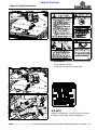
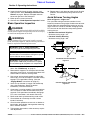
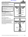
Drawbar Set-up
Refer to Figure 1-1:
Maintain proper distance, dimension “A”, between center
of drawbar hitch pin hole and end of tractor PTO shaft.
Hitch Type . . . . . . . . . . . . . . . . . . . . . . . . . . Draw Bar
540 RPM & 1 3/8" @ 1000 RPM Rear PTO Speed:
“A” . . . . . . . . . . . . . . . . . . . . . . . . . . . . . . . . 14"- 16”
“B”. . . . . . . . . . . . . . . . . . . . . . . . . . . . . . . . 8" - 10”
“C”. . . . . . . . . . . . . . . . . . . . . . . . . . . . . . .18" to 22"
1 3/4” @ 1000 RPM Rear PTO Speed:
“A” . . . . . . . . . . . . . . . . . . . . . . . . . . . . . . . 18" - 20”
“B”. . . . . . . . . . . . . . . . . . . . . . . . . . . . . . . 10" - 12”
“C”. . . . . . . . . . . . . . . . . . . . . . . . . . . . . . .18" to 22"
PTO to Drawbar Distance
Figure 1-1
PTO Speed
Rear PTO Speed:
Model RC5615 & RC6615 . . . . . . . . . . . . . 540 RPM
Model RCM5615 & RCM6615 . . . . . . . . . 1000 RPM
Hydraulic Outlets
The number of tractor hydraulic duplex outlets is
dependent upon how the Rotary Cutter is set-up.
• Two duplex outlets are required if the wings are folded
up and down simultaneously. (Factory standard)
IMPORTANT: PTO damage may occur if distances
“A” and “B” are not properly maintained.
IMPORTANT: A PTO adaptor should not be used.
Using a PTO adaptor can damage the PTO.
22273

12
Section 1: Assembly & Set-up
RC5615 & RC6615 (540 RPM) RCM5615 & RCM6615 (1000 RPM) Rotary Cutter 330-323M
4/20/15
Table of Contents
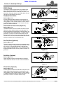
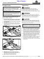
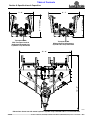
Hitch Types
The cutter is factory supplied with the standard clevis
hitch. Other optional hitches are available. They are
double swivel clevis hitch, bar-tite hitch, ball hitch, and
pintle hitch. See your nearest Land Pride dealer should
you want to change your hitch set-up.
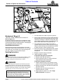
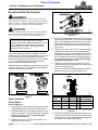
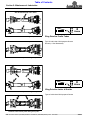
Standard Clevis Hitch
Refer to Figure 1-2:
A clevis leveling rod attached to the underside of the
clevis keeps the clevis parallel with tractor drawbar at all
cutting heights. Cutter rotation about the tractor drawbar
is limited to slots located in the clevis’ upper and lower
plates and drawbar hole size.
Double Swivel Clevis Hitch (Optional)
Refer to Figure 1-3:
The double swivel clevis hitch allows the cutter to pivot
about the tractor drawbar freely in two directions. It is
designed to reduce twisting torque on the cutter hitch and
tractor drawbar while cutting hillsides. The hitch swivel is
greasable. The clevis can be held horizontal with the
hitch bolt while backing tractor up to align the drawbar
with the clevis. The clevis must be shimmed with included
washers to reduce clevis and drawbar wear.
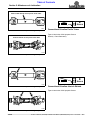
Bar-Tite Hitch (Optional)
Refer to Figure 1-4:
The bar-tite hitch functions the same as the double swivel
clevis hitch except it clamps directly to the drawbar. The
bar-tite hitch is sandwiched between hardened steel
plates minimizing drawbar wear. It has a bushing in the
tongue to extend hitch life. Bushing and hitch swivel are
greasable.
Ball Hitch (Optional)
Refer to Figure 1-5:
Cutter rotation about the tractor drawbar is limited to
swivel movement over the 2 5/16" tractor mounted ball.
Pintle Hitch (Optional)
Refer to Figure 1-6:
A leveling rod attached to the underside of the pintle hitch
keeps the pintle parallel with the tractor drawbar at all
cutting heights. Cutter rotation about the tractor drawbar
is limited to movement about the pintle connection. The
pintle hitch is ideal for a drawbar hammer strap.
Standard Clevis Hitch
Figure 1-2
Double Swivel Clevis Hitch
Figure 1-3
Bar-Tite Hitch
Figure 1-4
Ball Hitch
Figure 1-5
Pintle Hitch
Figure 1-6
26596
26598
26599
26600
26602

13
Section 1: Assembly & Set-up
4/20/15
RC5615 & RC6615 (540 RPM) RCM5615 & RCM6615 (1000 RPM) Rotary Cutter 330-323M
Table of Contents
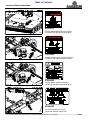
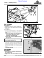
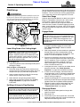
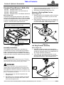
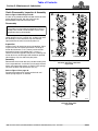
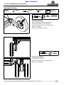
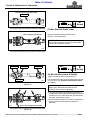
Hitch Assembly
Refer to Figure 1-8:
1. Remove and discard 1/2" nuts (#2) and bolts (#1).
2. Rotate hitch (#4) down into pulling position as shown
in Figure 1-7.
Refer to Figure 1-7:
3. Instructions “a” & “b” below are for cutters equipped
with standard clevis or pintle hitch. Skip to step 4 if
assembling double swivel clevis, bar-tite, or ball
hitch.
a. Attach clevis level rod (#2) to center deck lug and
clevis hitch (#1) with clevis pins (#9), flat
washers (#7), and cotter pins (#8).
b. Secure cotter pins (#8) by bending one or more
legs of each pin.
4. Attach hitch frame (#4) to leveling rods (#3) by
inserting 3/4" x 3" lg. bolts (#5) through the leveling
rod’s outside clevis plate, hitch frame, and then out
through the leveling rod’s inside clevis plate. Secure
bolts with nylock nut (#6). Draw nuts up snug, do not
tighten.
5. Leveling rod adjustment will be made after the cutter
is attached to the tractor.
Jack Assembly
Refer to Figure 1-9:
1. Attach parking jack (#4) to hitch frame and secure
with attached pin (#5).
2. Adjust jack up or down until clevis hitch is at drawbar
height.
IMPORTANT: Insert bolts (#5) from outside the hitch
frame. Inserting bolts from inside the hitch will result
in them interfering with tractor tires.
Figure 1-8
Figure 1-9
26612
22149
4
5
Figure 1-7
CENTER DECK LUG
26595

14
Section 1: Assembly & Set-up
RC5615 & RC6615 (540 RPM) RCM5615 & RCM6615 (1000 RPM) Rotary Cutter 330-323M
4/20/15
Table of Contents
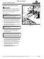
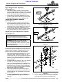
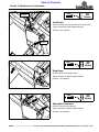
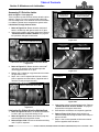
Standard Clevis Hitch Hook-up
!
DANGER
A Crushing Hazard exists when hooking-up equipment to a
tractor. Do not allow anyone to stand between tractor and
implement while backing-up to implement. Do not operate
hydraulic 3-Point lift controls while someone is directly
behind the tractor or near the implement.
Refer to Figure 1-10:
1. Make sure parking jack (#3) is properly attached to
cutter hitch and secured with attachment pin (#8).
2. Back tractor within close proximity of clevis (#9).
3. Raise or lower parking jack (#3) to align clevis (#9)
with tractor drawbar. Drawbar should fit between
lower and upper plates of clevis.
4. Back tractor up to cutter hitch until holes in drawbar
and clevis hitch (#9) are aligned.
5. Attach cutter to tractor drawbar with customer
supplied hitch pin (#1) and hairpin cotter (#2).
6. Lower parking jack (#3) until hitch weight is
supported by drawbar.
7. Remove parking jack (#3) from hitch and attach it to
the left-hand wing deck storage base with attachment
pin (#8). Make sure the base is level with or lower
than the head especially after the wings are folded
up. See cover picture for correct positioning.
8. Attach hitch safety chain (#4) to the tractor. Adjust
chain length to remove all slack except what is
necessary to permit turning. Lock chain hook
securely to the safety chain.
9. See “Driveline Installation” on page 17 and
“Hydraulic Hook-up” on page 17.
IMPORTANT: Jack attachment pin must be fully
inserted and secured before working on or around a
cutter not hooked to the tractor drawbar.
NOTE: Hitch pin (#1) and hairpin cotter (#2) are
supplied by customer.
IMPORTANT: Protect parking jack by storing it on
the left wing deck before moving the cutter. Make
sure the jack is stored with its base level or lower
than the head to prevent water and freeze damage.
Tractor Hookup (Standard Clevis Hitch Shown)
Figure 1-10
26603

15
Section 1: Assembly & Set-up
4/20/15
RC5615 & RC6615 (540 RPM) RCM5615 & RCM6615 (1000 RPM) Rotary Cutter 330-323M
Table of Contents
Double Swivel Clevis Hitch Hook-up
!
DANGER
A Crushing Hazard exists when hooking-up equipment to a
tractor. Do not allow anyone to stand between tractor and
implement while backing-up to implement. Do not operate
hydraulic 3-Point lift controls while someone is directly
behind the tractor or near the implement.
Refer to Figure 1-11:
1. Make certain parking jack (#3) is properly attached to
cutter and secured with attachment pin (#8).
2. Back tractor within close proximity of swivel
clevis (#2). Be sure to allow room to rotate swivel
clevis (#2) up without hitting tractor drawbar (#12).
3. Rotate swivel clevis (#2) up until level as shown and
insert 1"-8 x 5 1/2" GR5 hex bolt (#1) through lower
holes (A) to hold swivel clevis level.
4. Raise or lower parking jack (#3) until swivel
clevis (#2) is in-line with tractor drawbar (#12).
5. Back tractor up until holes in swivel clevis (#2) align
with hole in tractor drawbar (#12).
6. Remove bolt (#1) from holes (A) and insert it through
upper plate of clevis (#2), two flat washers (#9),
drawbar (#12), two more flat washers (#9), and lower
plate of clevis (#2). Add more flat washers (#9) if
necessary to take up any remaining slack.
7. Secure hex bolt (#1) with hex nut (#10). Draw hex nut
up snug. Do not tighten.
8. Screw hex jam nut (#11) up against hex nut (#10).
9. Hold hex nut (#10) and tighten jam nut (#11) to the
correct torque.
10. Lower parking jack (#3) until hitch weight is
supported by tractor drawbar.
11. Remove Parking jack (#3) from hitch frame and
attach it to the left-hand wing deck storage base with
attachment pin (#8). Make sure the base is level with
or lower than the head especially after the wings are
folded up. See cover picture for correct positioning.
12. Attach hitch safety chain (#4) to the tractor. Adjust
chain length to remove all slack except what is
necessary to permit turning. Securely lock chain
hook to the safety chain.
13. See “Driveline Installation” on page 17 and
“Hydraulic Hook-up” on page 17.
IMPORTANT: Jack attachment pin must be fully
inserted and secured before working on or around a
cutter not hooked to the tractor drawbar.
IMPORTANT: Protect parking jack by storing it on
the left wing deck before moving the cutter. Make
sure the jack is stored with its base level or lower
than the head to prevent water and freeze damage.
Tractor Hookup to Swivel Clevis Hitch
Figure 1-11
33919

16
Section 1: Assembly & Set-up
RC5615 & RC6615 (540 RPM) RCM5615 & RCM6615 (1000 RPM) Rotary Cutter 330-323M
4/20/15
Table of Contents
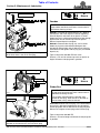
Bar-Tite Hitch Hook-up
Refer to Figure 1-12:
Attach Bar-Tite Hitch to Tractor Drawbar
1. Insert 1" x 5 1/2" hex bolt (#1) through hitch top
plate (#2), hitch bushing (#3), hitch wear plate (#4),
tractor drawbar (#5), and washer (#6) as shown.
Secure with 1" lock nut (#7). Tighten 1" lock nut
snugly to remove all play and then back nut
one-quarter turn. Do Not torque 1" lock nut.
2. Insert two 3/4" x 6" GR5 hex bolts (#8) through,
3/4" flat washers (#9), hitch top plate (#2), hitch wear
plate (#4), and formed hitch support (#10) as shown.
Secure with 3/4" lock nuts (#11).
3. Tighten 3/4" lock nuts to correct torque.
4. Remove 1" x 6 1/2" GR5 hex bolt (#12) and 1" lock
nut (#13) from hitch bushing (#3). Keep bolt and lock
nut for reuse.
Attach Tractor to Rotary Cutter
!
DANGER
A Crushing Hazard exists when hooking-up equipment to a
tractor. Do not allow anyone to stand between tractor and
implement while backing-up to implement. Do not operate
hydraulic 3-Point lift controls while someone is directly
behind the tractor or near the implement.
Refer to Figure 1-13:
1. Make certain parking jack (#3) is properly attached to
cutter and secured with attachment pin (#8).
2. Back tractor within close proximity of cutter hitch.
3. Raise or lower parking jack (#3) to align hitch
bushing (#10) with bolt hole in swivel clevis (#9).
4. Back tractor up to swivel clevis (#9) until hole in hitch
bushing (#10) aligns with holes in swivel clevis (#9).
5. Insert 1" x 6 1/2" GR5 hex bolt (#1) through swivel
clevis (#9) and hitch bushing (#10). Secure bolt with
lock nut (#2). Tighten lock nut snugly to remove all
play. Do Not torque 1" lock nut.
6. Lower parking jack (#3) until hitch weight is
supported by the drawbar.
7. Remove parking jack (#3) from hitch and attach it to
the left-hand wing deck storage base with attachment
pin (#8). Make sure the base is level with or lower
than the head especially after the wings are folded
up. See cover picture for correct positioning.
IMPORTANT: Jack attachment pin must be fully
inserted and secured before working on or around a
cutter not hooked to the tractor drawbar.
IMPORTANT: Protect parking jack by storing it on
the left wing deck before moving the cutter. Make
sure the jack is stored with its base level or lower
than the head to prevent water and freeze damage.
Bar-Tite Hitch Assembly to Tractor Tongue
Figure 1-12
8. Attach hitch safety chain (#4) to the tractor. Adjust
chain length to remove all slack except what is
necessary to permit turning. Securely lock chain
hook to the safety chain.
9. See “Driveline Installation” on page 17 and
“Hydraulic Hook-up” on page 17.
Tractor Hook-up to Bar-Tite Hitch
Figure 1-13
22265
26604

17
Section 1: Assembly & Set-up
4/20/15
RC5615 & RC6615 (540 RPM) RCM5615 & RCM6615 (1000 RPM) Rotary Cutter 330-323M
Table of Contents
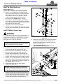
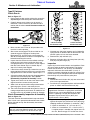
Driveline Installation
!
DANGER
Do not engage tractor PTO while hooking-up and unhooking
driveline or while someone is standing near the driveline. A
person’s body and/or clothing can become entangled in the
driveline resulting in serious injury or death.
!
WARNING
Always disengage PTO, place tractor in park or set park
brake, shut tractor engine off, remove switch key, and wait for
blades to stop before dismounting from tractor.
!
WARNING
Do not operate cutter above its rated PTO speed or machine
breakage may result.
!
WARNING
Make certain all driveline yokes are securely fastened at both
ends. A loose yoke can work free allowing the driveline to
rotate uncontrollably causing machine damage and bodily
injury or death to anyone nearby.
The main driveline may be either constant velocity type
or conventional type. Pull-collar couplers and retaining
bolts are used to connect the driveline to the tractor and
implement gearbox, respectively.
1. Park tractor and cutter in a straight line on a level
surface. Place gear selector in park or set park
brake, shut tractor engine off, and remove switch key.
2. Verify “Drawbar Set-up” dimensions on page 11 are
correct before installing driveline.
3. Remove knobs securing splitter gearbox guard and
remove splitter gearbox guard.
4. Remove bolts and lock nuts from bolted coupler end
of driveline (#5).
5. Attach bolted coupler end of driveline (#5) to splitter
gearbox input shaft with removed bolts and lock nuts.
Tighten lock nuts to the correct torque.
6. Fully collapse driveline by pushing tractor end of
driveline against the splitter gearbox.
7. Pull back on outer yoke locking collar and slide outer
yoke over tractor PTO shaft.
IMPORTANT: Do not attempt to operate a 540 RPM
driveline at 1,000 RPM or a 1,000 RPM driveline at
540 RPM. Many tractors provide both 540 and 1,000
RPM PTO modes. Check your tractor’s manual to
determine its capabilities.
IMPORTANT: The driveline must be lubricated
before putting it into service. Refer to Lubrication
Points on page 46.
8. Release collar and continue to push yoke onto the
tractor PTO shaft until locking collar snaps in place.
9. The driveline should now be moved back and forth to
ensure both ends are secured to the PTO shaft and
gearbox input shaft. Reattach any end that is loose.
10. Secure front chain (#6) on driveline (#5) around a
rigid point on the tractor such as the drawbar. Do not
connect the chain to the PTO shield.
11. Attach safety chain located on the other end of
driveline (#5) to the cutter’s main frame to restrict
driveline inner shield from rotating. Re-latch safety
chain to driveline guard.
12. Replace splitter gearbox guard. Hand tighten knobs.
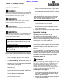
Hydraulic Hook-up
The required number of duplex outlets at the tractor is
dependent upon how the cutter is set-up.
The standard cutter is equipped with three hydraulic
cylinders with one in the center for lifting the cutter and
one on each wing for folding the wings simultaneously. All
three cylinders are set-up for single action
(one-way) operation.
Each duplex outlet on your tractor can perform only one
operation. One outlet is needed for lifting the cutter and
one for lifting the wings simultaneously. A third outlet is
required if the wings are lifted independently. This will
also require replumbing the hydraulics to the wing
cylinders.
Your Land Pride dealer can help you determine the best
configuration that will match your needs and your tractor
capabilities. Optional control valve kits are available if the
tractor does not have the required number of duplex
outlets. For additional information, see Hydraulic
Accessories on page 30.
!
DANGER
Hydraulic fluid under high pressure can penetrate skin. Wear
protective gloves and safety glasses or goggles when working
with hydraulic systems. Use a piece of cardboard or wood
rather than hands when searching for hydraulic leaks. If
hydraulic fluid is injected into the skin or eyes, it must be
treated by a doctor familiar with this type of injury within a
few hours or gangrene may result. DO NOT DELAY.
Refer to Figure 1-13 on page 16:
1. Route cylinder hoses (#7) through hose support loop
and connect to tractor remote outlets. If tractor has a
float option on one of the outlets, connect wing lift
hydraulic hose to that outlet.
2. Hydraulic lines are purged after completing Right and
Left Wing Set-up instructions.
IMPORTANT: Two small chains are supplied with
each driveline. These chains must be attached to the
driveline shields and adjacent equipment to keep
inner and outer driveline shields from rotating.

18
Section 1: Assembly & Set-up
RC5615 & RC6615 (540 RPM) RCM5615 & RCM6615 (1000 RPM) Rotary Cutter 330-323M
4/20/15
Table of Contents
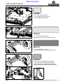
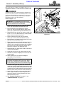
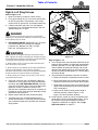
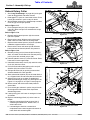
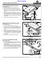
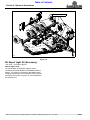
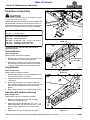
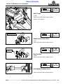
Right & Left Wing Set-ups
Refer to Figure 1-14:
1. Make sure cutter is parked on a level surface.
2. Place gear selector in park, set tractor control lever
for the wing cylinder in float position, shut tractor
engine off or set park brake, and remove switch key.
3. Loosen turnbuckle jamb nuts (#7) and lengthen
turnbuckles (#11) until bolted connections (#5) are
approximately 10 1/2" apart.
!
DANGER
Keep everyone out of the area where the wing decks will
unfold into. A wing that falls suddenly on a person will cause
serious bodily injury or death.
4. SEE DANGER ABOVE. Shipping bar (#1) is factory
installed between the two wings for shipping
purposes only. Remove nuts (#8), carriage
bolts (#4), and shipping bar (#1).
!
WARNING
The wing decks are shipped leaning in towards the center
deck. A person will need to manually push the decks out pass
vertical before they will lower down to the ground under their
own weight. Before pushing on the wing decks:
• Make certain no one is in the area where the decks will
lower down into as they unfold.
• Make certain you are standing on the center deck behind
and away from hydraulic hoses, hydraulic cylinders,
gearboxes and drivelines so that you do not become entangled
in them as they move while the decks are unfolding.
• Make certain your footing is secure and you are clear of
any possible pinch points.
5. Once you are certain the area where the deck will
unfold into is clear and you are safely positioned on
the center deck (SEE WARNING ABOVE), manually
push on the right wing until it starts to fall down to the
ground on its own. It should fall slowly as the
hydraulic line is orificed to control its fall. If it does not
fall down on its own, then continue lowering the wing
deck with tractor hydraulics.
6. Repeat step 5 above to lower the left wing deck.
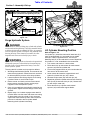
7. Transport locks (#2) are mounted backwards as
shown. Remove four 1/2" nuts (#6), four lock washers
(#9), and one transport lock (#2) from each hydraulic
wing cylinder.
Wing Rework (RH Wing Shown)
Figure 1-14
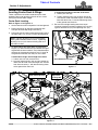
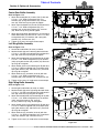
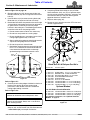
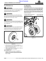
Refer to Figure 1-15:
8. Turn transport locks (#3) around and reinstall on the
hydraulic wing cylinders as shown with removed lock
washers (#9) and 1/2" nuts (#6). Make certain the
amber reflector face towards the front and the red
reflector face towards the back. Hold transport lock
up off the cylinder rod and tighten 1/2"-13 nuts (#6) to
the correct torque.
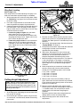
9. Check driveline for adequate clearance as follows:
a. Make sure driveline is attached to tractor & cutter.
b. Raise center deck fully up with tractor hydraulics.
Remove transport lock from center deck cylinder.
c. Slowly lower and raise cutter to its most lower and
upper limits while observing clearances between
hitch and driveline.
d. Adjust tractor drawbar height and/or length if
driveline interferes. Refer to Figure 1-1 on
page 11 for correct drawbar position.
10. Cycle hydraulic system by raising and lowering the
center deck cylinder and wing fold cylinders. It may
be necessary to purge the hydraulic system of
trapped air if operation is sluggish. See “Purge
Hydraulic System” on page 19.
2671
Page is loading ...
Page is loading ...
Page is loading ...
Page is loading ...
Page is loading ...
Page is loading ...
Page is loading ...
Page is loading ...
Page is loading ...
Page is loading ...
Page is loading ...
Page is loading ...
Page is loading ...
Page is loading ...
Page is loading ...
Page is loading ...
Page is loading ...
Page is loading ...
Page is loading ...
Page is loading ...
Page is loading ...
Page is loading ...
Page is loading ...
Page is loading ...
Page is loading ...
Page is loading ...
Page is loading ...
Page is loading ...
Page is loading ...
Page is loading ...
Page is loading ...
Page is loading ...
Page is loading ...
Page is loading ...
Page is loading ...
Page is loading ...
Page is loading ...
Page is loading ...
Page is loading ...
Page is loading ...
Page is loading ...
Page is loading ...
-
 1
1
-
 2
2
-
 3
3
-
 4
4
-
 5
5
-
 6
6
-
 7
7
-
 8
8
-
 9
9
-
 10
10
-
 11
11
-
 12
12
-
 13
13
-
 14
14
-
 15
15
-
 16
16
-
 17
17
-
 18
18
-
 19
19
-
 20
20
-
 21
21
-
 22
22
-
 23
23
-
 24
24
-
 25
25
-
 26
26
-
 27
27
-
 28
28
-
 29
29
-
 30
30
-
 31
31
-
 32
32
-
 33
33
-
 34
34
-
 35
35
-
 36
36
-
 37
37
-
 38
38
-
 39
39
-
 40
40
-
 41
41
-
 42
42
-
 43
43
-
 44
44
-
 45
45
-
 46
46
-
 47
47
-
 48
48
-
 49
49
-
 50
50
-
 51
51
-
 52
52
-
 53
53
-
 54
54
-
 55
55
-
 56
56
-
 57
57
-
 58
58
-
 59
59
-
 60
60
-
 61
61
-
 62
62


Ask a question and I''ll find the answer in the document
Finding information in a document is now easier with AI
Related papers
-
 Land Pride Brush Cutter RC 55 User manual
-
 Land Pride RC 55 User manual
-
 Land Pride RCM5014 Features And Benefits
-
 Land Pride RCR3515 User manual
-
 Land Pride RC5615 User manual
-
Land Pride RC5610 User manual
-
 Land Pride FDR35 User manual
-
 Land Pride RC50 User manual
-
 Land Pride 318-586A User manual
-
 Land Pride RC5510 User manual


Other documents
-
Franke 127.0199.258 Datasheet
-
Apex ADPT-637 User manual
-
Toro 121-5698 User manual
-
Swisher PowerBlade PBH-1560 Assembly Instructions
-
BENDIX PNU-064 User manual
-
-
Ultra-Fab Products 48-979014 User manual
-
Bad Boy 5´ Cutter Owner's Operation Manual
-
Skyjacker TCL35 Installation guide
-
Buhler FK324 User manual