Page is loading ...

OS550A/OS550AM/
OS550A-BB Series
Industrial Infrared
Thermometer/Transmitter
TM
e-mail: [email protected]
For latest product manuals:
www.omegamanual.info
Shop online at
omega.com
User’s Guide
STANDARD PLASTIC CASE - OS550A
ALUMINUM CASE - OS550AM
(OPTIONAL)
NORWALK, CT

omega.com [email protected]
The information contained in this document is believed to be correct, but OMEGA accepts no liability for any errors it contains,
and reserves the right to alter specifications without notice.
Servicing North America:
U.S.A. Omega Engineering, Inc.
Headquarters: Toll-Free: 1-800-826-6342 (USA & Canada only)
Customer Service: 1-800-622-2378 (USA & Canada only)
Engineering Service: 1-800-872-9436 (USA & Canada only)
Tel: (203) 359-1660 Fax: (203) 359-7700
e-mail: [email protected]
For Other Locations Visit omega.com/worldwide

NOTE
i
Unpacking Instructions
Remove the Packing List and verify that you have received all equipment, including
the following (quantities in parentheses):
OS550A or OS550A-BB Series Infrared Thermometer with Sensor Head (1)
RS-232 Cable with connector/adapter (OS552A, thru OS555A) only (1)
CD Software ( OS552A, thru OS555A) only (1)
User’s Guide (1)
Optional Accessories:
From the Technical Library of ____________________________________
If you have any questions about the shipment, please call the Customer Service
Department at
1-800-622-2378 or 203-359-1660. We can also be reached on the Internet at
omega.com
e-mail: [email protected]
When you receive the shipment, inspect the container and equipment for signs of
damage. Note any evidence of rough handling in transit. Immediately report any
damage to the shipping agent.
The carrier will not honor damage claims unless all shipping material
is saved for inspection. After examining and removing contents, save
packing material and carton in the event reshipment is necessary.
Model No. Description
OS550-MN Mounting Nut
OS550-MB Mounting Bracket
OS550-AP Air Purge Collar
OS550-MF Mounting Flange
OS550-WC Water Cool Jacket
OS550-LS Laser Sight
PSS-12 Power Supply, 12V regulated
PSR-24S Reg. 24 Vdc Power Supply
Screw Terminals
PSR-24L Reg. 24 Vdc Power Supply
Stripped Leads
WRS232-USB Wireless RS-232 Transceiver
OS550A-PCAB-15 Power/output cable connector 15 ft
OS550A-PCAB-100 Power/output cable connector 100 ft

ii
OS550A Series
Industrial Infrared Thermometer
This page is intentionally blank

TABLE OF
CONTENTS
OS550A/OS550A-BB Series
Industrial Infrared Thermometer
iii
Page
Unpacking Instructions ..................................................................... i
Chapter 1 General Description .................................................... 1-1
1.1 Introduction ......................................................................................... 1-1
1.2 Thermometer Features ....................................................................... 1-2
1.2.1 Display Details ..................................................................................... 1-3
1.2.2 Parts of the Thermometer .................................................................. 1-4
Chapter 2 Installing the Handheld Infrared Thermometer ............ 2-1
2.1 Installation ........................................................................................... 2-1
2.2 Sensor Head Dimensions ................................................................... 2-2
2.3 Main Display Housing Dimensions .................................................. 2-3
2.4 OS550A-BB Dimensions ..................................................................... 2-5
2.5 Mounting Bracket Dimensions (OS550-MB) .................................... 2-6
2.6 Mounting Nut Dimensions (OS550-MN) ......................................... 2-6
2.7 Mounting Flange Dimensions (OS550-MF) ..................................... 2-7
2.8 Air Purge Collar Dimensions (OS550-AP) ....................................... 2-7
Chapter 3 Using the Infrared Thermometer .................................. 3-1
3.1 Using the Infrared Thermometer ..................................................... 3-1
3.1.1 Water Cool Jacket Accessory ............................................................. 3-1
3.2 How To Wire the Thermometer ........................................................ 3-2
3.3 Operating the Thermometer .............................................................. 3-3
3.3.1 Field of View Charts ............................................................ 3-4, 3-5, 3-6
3.4 Measurement Techniques ................................................................... 3-7
3.5.1 Adjusting Emissivity ......................................................................... 3-10
3.5.2 Calculating Temperature Values ..................................................... 3-11
3.5.3 Changing the Temperature for °F to °C ......................................... 3-11
3.5.4 Turning the Display Backlighting ON/OFF .................................. 3-11
3.5.5 Using the Alarm Functions .............................................................. 3-12
3.5.6 Using Ambient Target Temperature Compensation .................... 3-14
3.5.7 PC Interface Software ........................................................................ 3-16
3.5.7.1 PC Interface Commands .................................................................. 3-21
3.5.8 Storing Temperature Data On Command ..................................... 3-23
3.5.9 Reviewing Stored Temperature Data ............................................ 3-23
3.5.10 Logging Temperature Data In Real Time ...................................... 3-24
3.5.11 Erasing The Temperature Data From Memory ............................ 3-25
Chapter 4 Laser Sight Accessory ................................................. 4-1
4.1 Warnings and Cautions ..................................................................... 4-1
4.2 Description ........................................................................................... 4-2
4.3 Operating the Laser ............................................................................. 4-3
4.3.1 Installing the Laser Sight onto the Thermometer ........................... 4-3
4.3.2 Powering the Laser Sight Accessory ................................................. 4-3

iv
TABLE OF
CONTENTS
OS550A/OS550A-BB Series
Industrial Infrared Thermometer
Page
Chapter 5 Maintenance .............................................................. 5-1
5.1 Cleaning the Lens ............................................................................... 5-1
5.2 Calibrating the Thermometer ........................................................... 5-1
Chapter 6 Troubleshooting Guide ............................................... 6-1
Chapter 7 Specifications ............................................................. 7-1
Chapter 8 Glossary of Key Strokes ............................................. 8-1
Appendix A How Infrared Thermometry Works ......................... A-1
Appendix B Emissivity Tables ..................................................... B-1
Appendix C Determining an Unknown Emissivity ....................... C-1
Index ............................................................................................. I-1

v
List of Figures
Figure Description Page
1-1 Display and Keypad View ................................................ 1-3
1-2 OS550A/OS550AM/OS550A-BB Series Industrial
Infrared Thermometer Front View ............................... 1-4
2-1 Sensor Head Dimensions .................................................. 2-2
2-2 Plastic Housing Dimensions ............................................. 2-3
2-2A OS550AM Aluminum Housing Dimensions ................. 2-4
2-3 OEM Style Main Display
with Mounting Plate (OS550A-BB) ............................... 2-5
2-4 Mounting Bracket Dimensions
(OS550-MB) .......................................................................2-6
2-5 Mounting Nut Dimensions
(OS550-MN) ..................................................................... 2-6
2-6 Mounting Flange Dimensions
(OS550-MF) ...................................................................... 2-7
2-7 Air Purge Collar Dimensions
(OS550-AP) ....................................................................... 2-7
3-1 Water Cool Jacket Dimensions
(OS550-WC) ..................................................................... 3-1
3-2 OS550A-BB Wire Connection ........................................... 3-2
3-3 External Relay Wiring Diagram ....................................... 3-3
3-4 Typical Transmission Installation .................................... 3-3
3-5 Field of View Positions ...................................................... 3-3
3-6 OS550A Series (-1 FOV) ..................................................... 3-4
3-7 OS550A Series (-2 FOV) ..................................................... 3-4
3-8 OS550A Series (-3 FOV) ..................................................... 3-5
3-9 OS550A Series (-4 FOV) ..................................................... 3-5
3-10 OS550A Series (-5 FOV) ..................................................... 3-6
3-11 OS550A Series (-6 FOV) ..................................................... 3-6
3-12 OS555A FOV ....................................................................... 3-7
3-13 Visual Function Flow Chart .............................................. 3-9
3-14 Personal Computer Connection ..................................... 3-16
4-1 Laser Sighting Accessory (OS550-LS) ............................. 4-2
4-2 General Dimansions ...........................................................4-3
A-1 Infrared Temperature ...................................................... A-1
A-2 Blackbody Spectral Distribution ..................................... A-2
A-3 Field of View of a Thermometer/Transmitter .............. A-4
C-1 Determining Emissivity With Masking Tape ................ C-2
C-2 Determining Emissivity with a Drilled Hole ................ C-3
LIST OF
FIGURES
OS550A/OS550A-BB Series
Industrial Infrared Thermometer

vi
CAUTION & SAFETY INFORMATION
If the equipment is used in a manner not specified in this manual, the
protection provided by the equipment may be impaired.
The Installation category is one (1).
The output terminals of this product are for use with equipment (digital
meters, chart recorders, etc.) which have no accessible live parts. Such
equipment should comply with all the applicable safety requirements.
Do not operate the equipment in flammable or explosive environments.
The unit comes with two 4.6 m (15') shielded multi-conductor cables. The
sensor cable is a five conductor, 24 AWG stranded wire with a rating of 600
Vdc, 205°C (401°F) PTFE insulation. The power/output cable is an eight
conductor 24 AWG stranded wire with rating of 300 Vdc, 105°C (221 °F)
PVC insulation.
Power must be disconnected before making any electrical connections.
The recommended power supply should be VDE or UL approved. Rating:
8-24 Vdc @ 100 mA minimum power with overload protection, current
limited to 500 mA.
The supply voltage to the transmitter should not exceed 24 VDC.
There is only one fuse in the OS550A. Disconnect power before replacing the
fuse. The fuse must be replaced with one of identical size and rating. Fuse
Specifications: 125 mA/250 Vac, Time-lag, 5 x 20 mm with UL and/or VDE
Approvals such as Wickmann No. 19195-028.
All connections made to the thermometer should be made via a stranded
wire, shielded cable, 24 AWG (min), such as OMEGA Engineering’s Model
TX4 or TX8 series. Wiring requirements for this unit are Class II.
SAFETY WARNINGS AND IEC SYMBOLS
This device is marked with international safety and hazardous symbols
in accordance with IEC1010. It is important to read and follow all
the precautions and instructions in this manual before operating or
commissioning this device as it contains important information relating to
safety and EMC. Failure to follow all the safety precautions may result in
injury and/or damage to your equipment.
IEC Symbol Description
Caution - Refer to the accompanying
document(s).
Direct Current
Laser Symbol
OS550A/OS550A-BB Series
Industrial Infrared Thermometer

1-1
General Description
1
1.1 Introduction
The OS550A Series Industrial Infrared (IR) Thermometers provide
non-contact temperature measurement up to 4500°F (2482°C).
They offer effective solutions for many non-contact temperature
applications, including the following:
• Predictive Maintenance: Tracking temperature shifts which
indicate pending failure in solenoid valves.
• Energy Auditing: Locating wall insulation voids to reduce
building heating costs.
• Food Processing: Taking accurate temperature readings
without direct contact with the food or packaging material.
• Annealing Processing: Monitoring surface temperatures
of metals while it is inside an oven by seeing through glass
window.
The IR thermometer provides a custom backlit dual digital LCD
that displays both current and minimum, maximum, average or
differential temperatures. This versatile instrument provides:
• Measurable target distances from 5 inches (12.7 cm) to
approximately 200 feet (61 m)
• Emissivity adjustable from 0.1 to 1.00 in 0.01 steps provides
ease of use when measuring a variety of surfaces.
• Continuous temperature measurement up to 10 times per
second.
• Audible and visual alarms. The high and low alarm points
are set via the keypad.
• Analog output, 1 mV/degree, 4-20mA or 0-5VDC
which allows interfacing with data acquisition equipment
(including chart recorders, data loggers and computers)
• Two way RS232 serial communication to a PC. This allows
downloading data for further analysis (OS552A, OS553A
and OS554A, OS555A).
• Ambient target temperature compensation. This provides
more accuracy for measuring low emissivity targets.
• Record up to 800 temperature data points either continuos or
on demand. Review the recorded data on the thermometer
LCD, as well as downloading the data to a PC (OS553A and
OS554A, OS555A).
• Backlit display useful in low ambient light conditions
• Laser Sighting is optional.
• High and Low Alarm outputs to drive external Mechanical
Relays

General Description
1
1-2
General Description
1.2 Thermometer Features
The thermometer is easy to use:
• Temperature readings are switchable from °F to °C via the
keypad.
• Parameters, such as target material emissivity and alarm
setpoints, can be set and remain in non-volatile memory
until reset.
This instrument has a rugged and functional design, including:
• Sealed keypad display.
Table 1-1. OS550A Series Industrial Infrared Thermometer Features
*or 3°F whichever is greater - 2% of rdg for temps > 2000°F on OS555A
Features OS551A OS552A OS553A OS554A OS555A
Accuracy* ±1% rdg ±1% rdg ±1% rdg ±1% rdg ±1% rdg
Range -10 to 750°F -10 to 1000°F -10 to 1600°F 0 to 2500°F 1000 to 4500°F
(-23 to 400°C) (-23 to 538°C) (-23 to 870°C) (-18 to 1371°C) (538 to 2482°C)
Emissivity adjustable adjustable adjustable adjustable adjustable
Backlit Dual
standard standard standard standard standard
Display
Distance to
Spot Ratio
Differential
standard standard standard standard standard
Temperature
Min/Max
standard standard standard standard standard
Temperature
Average
standard standard standard standard standard
Temperature
High Alarm standard standard standard standard standard
Low Alarm – standard standard standard standard
Ambient Target
Temperature – standard standard standard standard
Compensation
RS-232 Interface – standard standard standard standard
Data Storage – – standard standard standard
Audible Alarm
standard standard standard standard standard
& Output
Analog Outputs 1 mV/Degree or 0/5 Vdc or 4/20 mA
See Field of View Charts, pages 3-4, 3-5, 3-6, 3-7

1-3
General Description
1
General Description
1.2.1 Display Details
MAX750
658
AT C
HAL
LAL
PRN
°F °C
SET
FUNC
F-C
▼
▼
-
2
1
10
11
9
8
3
4
5
6
7
Figure 1-1. Display and Keypad View
Table 1-2. Display Details
Key Description
1
Display Mode displays one of the following:
E (Emissivity) HAL (High Alarm Setpoint)
MAX (Maximum Temperature) LAL (Low Alarm Setpoint - OS552A thru OS555A)
MIN (Minimum Temperature) AMB (Ambient Target Temp - OS552A thru OS555A)
dIF (Differential Temperature) PRN (Print Data - OS552A, thru OS555A)
AVG (Average Temperature) MEM (Store Temperature Data - OS553A thru OS555A)
LOG (Log Temp Data- OS553A thru OS555A)
2
Data associated with one of the Display Modes
3
Backlighting Icon - allows the display to be viewed under low ambient light
4
Displays the units of measure in either °F or °C
5
Main display - displays the current temperature
6
Enables or Disables alarms or LOG. Resets MAX, MIN, DIF,AVG, temperatures
7
s for incrementing data; is for turning on/off the backlighting
8
tfor decrementing data; is for changing the units of measure from
°F to °C or vice versa
9
Function key for scrolling through the display modes
Display Icons
Ambient Target Temperature Low Alarm
High Alarm Data Transmisson thru RS232
High or Low Alarm condition LED
10
11

General Description
1-4
General Description
1
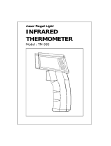
1.2.2 Parts of the Thermometer/Transmitter
Figure 1-2.
OS550A/OS550AM/OS550A-BB Series Industrial Infrared Thermometer
Front View
The display is shown in more detail in Figure 1-1 and described in Table 1-2.
Note: There are no user-serviceable parts in the thermometer.
Shown with optional mounting bracket,
OS550-MB and mounting nut OS550-MN
Sensor Head
NEMA4 Plastic Housing, Keypad, Display
and Output Electronics (OS550A Series)
Sensor
Cable with
Quick
Disconnect
Power/
Output
Cable with
Quick
Disconnect
OEM Style
Keypad, Display,
and Electronics
(OS550A-BB Series)
NEMA4
Aluminum
Housing,
(OS550AM
Series)

2-1
2
2.1 Installation
2.1.1 Sensor Head Installation
The OS550A’s sensor head is made of black anodized aluminum. Both ends
of the sensor head come with a 1
1
⁄2 - 20 standard threaded mounting
connection. The sensor head is connected to the main display electronics
via a 15’ shielded cable and environmentally sealed twist lock connector.
Mounting accessories are available. See page 2-2 for sensor head
dimensions.
If the sensor head is used in an environment where the
ambient temperature is above 122°F (50°C), the water
cool jacket accessory (OS550-WC) must be used to
maintain accuracy and prevent damage to the sensor
head. See Chapter 3.1.
2.1.2 OS550A Series NEMA Plastic Housing Installation
The OS550A Series’ main display and electronic’s housing is
environmentally sealed and weather tight. Mounting ears are provided
making mounting easy. Mount the main electronics assembly in a location
that you can easily access to view the LCD and make program changes to
the unit. See case and mounting plate dimensions on page 2-3.
2.1.2A OS550AM Series NEMA Aluminum Housing
The OS550AM Series is available in a NEMA Aluminum Housing as an
option. Refer to figure 2-2A for case and mounting hole dimensions.
2.1.3 OS550A-BB OEM Style Display Installation
The main display and electronics assembly is provided with an aluminum
mounting plate making installation of this OEM style system economical
and easy to customize. Assembly should be mounted in a location that is
free of dirt, grease, oils, and other liquids. See mounting dimension
on page 2-5.
Installing the Infrared Thermometer
NOTE

Installing the Infrared Thermometer
2
2-2
2.2 Sensor Head Dimensions
Fig. 2-1. Sensor Head Dimensions
29.2
(1.15)
29.2
(1.15)
41.1
(1.62) DIA.
DIMENSIONS: mm (in)
38.1
(1.50) DIA.
109.2
(4.30)
160.3
(6.31)
1
1
⁄
2
x 20 THREAD
1
1
⁄
2
x 20 THREAD

2-3
Installing the Infrared Thermometer
2
131.3
(5.17) TYP.
120.6
(4.75) TYP.
Ø 4.37 (0.172) MOUNTING HOLE
(4 PLACES)
50.0
(1.97) TYP.
80.10
(3.15) TYP.
DIMENSIONS: mm (in)
Fig. 2-2. Plastic Housing Dimensions
2.3 OS550A Main Display Standard Plastic Housing Dimensions

Installing the Infrared Thermometer
2
2-4
FUNC SET
°F-°C
-
90.0
(3.54)
60.0
(2.36)
DIMENSIONS: mm (in)
100.8
(3.97)
115.3
(4.54)
4.7 (0.187) DIA.
MOUNTING HOLES
2 PLCS
High/Low Alarm
®
OS550A SERIES INFRARED
INDUSTRIAL PYROMETER
2.3A OS550AM Aluminum Housing Dimensions
Fig. 2-2A. Aluminum Housing Dimensions

2-5
2.4 OS550A Display Electronics Dimensions
Fig. 2-3. OEM Style Main Display with Mounting Plate
SET
FUNC
F-C
▼
▼
-
26.4
(1.04)
31.0
(1.22)
57.4
(2.26)
Ø 5.16 (0.203) THRU TYP. (4 PLACES)
WILL FIT UP TO A
#10 SCREW OR BOLT
118.4
(4.66)
26.4
(1.04)
57.4
(2.26)
5.1
(.20) TYP.
91.4
(3.60)
DIMENSIONS: mm (in)
Installing the Infrared Thermometer
2

2-6
2.4 Mounting Bracket Dimensions (OS550-MB)
Fig. 2-4. Mounting Bracket Dimensions
2.5 Mounting Nut Dimensions (OS550-MN)
Fig. 2-5 Mounting Nut Dimensions
50.8
(2.00)
57.2
(2.25)
38.61
Ø (1.520)
88.9
(3.50)
6.4
(.25) REF
88.9
(3.50)
12.7
(.50)
25.4
(1.00)
28.58
(1.125)
22.23
(.875)
25.4
(1.00)
3.18
R (.125)
3.18
R (.125)
TYP. 2 PLACES
DIMENSIONS: mm (in)
.020 x 45
CHAMFER
BOTH SIDES
.020 x 45
CHAMFER
BOTH SIDES
1 1/2-20-2B THRU MED. DIAMOND NURL
0.250
C
L
Ø 2.00
Installing the Infrared Thermometer
2

2-7
2.6 Mounting Flange Dimensions (OS550-MF)
2.7 Air Purge Collar Dimensions (OS550-AP)
6.35
(.250)
38 (1.5) - 20 THREAD
6.35 (.250)
THRU TYP. (3 PLACES)
3 HOLES ON Ø 71.1 (2.80)
BOLT CIRCLE
TYP. 3 PLACES
0.120
Ø 89 (3.5)
DIMENSIONS: mm (in)
21.59
(0.850)
1/8 N.P.T. TAP THRU
51 (2.0) DIA.
38 (1.5) – 20 THREAD
DIMENSIONS: mm (in)
Fig. 2-6 Mounting Flange Dimensions
Fig. 2-7 Air Purge Collar Dimensions
Installing the Infrared Thermometer
2

Installing the Infrared Thermometer
2
2-8
Notes
/