Page is loading ...

DIGITAL
THERMOMETER
WITH TRICOLOR LCD
INSTRUCTION MANUAL
THIS MANUAL CONTAINS IMPORTANT INFORMATION REGARDING SAFETY, OPERATION,
MAINTENANCE AND STORAGE OF THIS PRODUCT. BEFORE USE, READ CAREFULLY AND
UNDERSTAND ALL CAUTIONS, WARNINGS, INSTRUCTIONS AND PRODUCT LABELS.
FAILURE TO DO SO COULD RESULT IN SERIOUS PERSONAL INJURY AND/OR PROPERTY
DAMAGE.
IF YOU SHOULD HAVE ANY QUESTIONS OR EXPERIENCE A PROBLEM WITH YOUR ALLTRADE
PRODUCT, DO NOT RETURN THIS PRODUCT TO THE STORE. PLEASE CALL OUR CUSTOMER
SERVICE DEPARTMENT AT 1-800-423-3598. BEFORE YOU CALL, HAVE THE FOLLOWING
INFORMATION AVAILABLE: MODEL No., DATE PURCHASED AND STORE LOCATION. AN
ALLTRADE REPRESENTATIVE CAN RESOLVE YOUR PROBLEM OVER THE PHONE. IF YOU
WOULD LIKE TO MAKE A SUGGESTION OR COMMENT, GIVE US A CALL OR EMAIL US AT:
[email protected]. YOUR FEEDBACK IS VITAL TO US.
Model no 240022
Component No. 692650

TABLE OF CONTENTS
INTENDED USE .............................................................. 1
GENERAL SAFETY RULES ...................................................... 1-3
RECOGNIZE SAFETY SYMBOLS, WORDS AND LABELS ......................... 1
LASER SAFETY ......................................................... 2
TOOL USE AND CARE ................................................... 2-3
FUNCTIONAL DESCRIPTION .................................................... 3-4
LCD INDICATIONS AND SYMBOLS ......................................... 4
BUTTON FUNCTIONS .................................................... 4
BATTERY INSTALLATION/REPLACEMENT ......................................... 4-5
OPERATING INSTRUCTIONS .................................................... 5-8
°C / °F TEMPERATURE UNIT SETTING ...................................... 6
REFERENCE TEMPERATURE SETTING & MEASUREMENT ....................... 6
EMISSIVITY ADJUSTMENT ............................................... 7-8
CLEANING AND STORAGE ...................................................... 9
SPECIFICATIONS ............................................................. 9
1 YEAR LIMITED WARRANTY ................................................... 10
FCC INFORMATION ........................................................... 10
INTENDED USE
This product is intended for consumer use only. It is designed to be used for non-contact temperature measurement
by measuring the amount of infrared energy radiated from the object’s surface.
GENERAL SAFETY RULES
READ AND UNDERSTAND ALL INSTRUCTIONS. Failure to follow all
instructions in this manual may result in severe personal injury or death. Keep this manual and refer to it
for Safety Instructions, Operating Procedures and Warranty.
SAVE THESE INSTRUCTIONS FOR FUTURE REFERENCE.
RECOGNIZE SAFETY SYMBOLS, WORDS AND LABELS
WARNING indicates a potentially hazardous
situation which, if not avoided, could result in death or serious
injury.
CAUTION indicates a potentially hazardous situation which, if
not avoided, may result in minor or moderate injury.
This product contains chemicals known to the State of California to cause
cancer, birth defects and other reproductive harm. For more information go to www.P65Warnings.ca.gov.
1

LASER SAFETY
Pointing a laser and interfering with the operation
of an aircraft is a felony punishable by fine and
imprisonment.
The laser guide used in the tool is Class II.
The laser shall be used and maintained in accor-
dance with the manufacturer’s instructions.
The use of optical instruments with this product
will increase eye hazard.
Use of controls or adjustments or performance of procedures other than those specified
herein may result in hazardous radiation exposure.
Do not stare into the laser beam.
Never aim the beam at any person or an object other than the work piece.
Avoid indirect exposure via reflective surfaces, such as glass and mirrors.
Store out of reach of children. Equipment should be in a high location or locked up to keep out of reach
of children. It is not a toy.
Do not tamper with the laser output. Changing the performance of the laser to increase its output
is prohibited. Any claim for damages or injuries resulting from not following these instructions will be
refused.
Never operate laser if the unit is defective or the cover or seal is damaged.
There are no user-serviceable parts in the laser device. The laser unit must be returned to the
factory for any service or repair. Service or repair must be handled by authorized factory trained techni-
cians.
Be careful with this tool. Striking or jarring it, especially on the laser housing can affect its accuracy.
TOOL USE AND CARE
Use the product only as specified in this manual.
Avoid exposing this device to EMF (electro-magnetic fields) from arc welders, induction
heaters, etc. OR exposing to static electricity.
To prevent sensor damage, do not point the sensor lens directly at the sun or any other
source of strong infrared light.
AVOID EXPOSURE
CAUTION
Laser Radiation is emitted from this aperture
DO NOT STARE INTO BEAM OR VIEW
DIRECTLY WITH OPTICAL INSTRUMENTS
LASER RADIATION
1 MW MAX OUTPUT AT 630-670 NM
CLASS II LASER PRODUCT
DIODE LASER
Complies with FDA 21CFR, 1040.10 & 1040.11
0601000040
Made in China
Serial No:
XXXXXXXXX
Alltrade Tools LLC
IR Thermometer Label
2

Do not leave the thermometer on or near objects of high temperature exceeding 158°F.
Be certain there is no condensation on the lens prior to taking measurements. Allow 10
minutes for condensation to dissipate as needed.
Shiny surfaces result in lower than actual temperature measurements.
For the most accurate temperature measurements, aim the infrared thermometer perpen-
dicular to the target.
The IR thermometer cannot measure through transparent surfaces such as glass and plastic.
It will measure the surface temperature instead.
Steam, dust, smoke and/or vapours can prevent accurate measurement by obstructing the
unit’s optics. For better accuracy, keep the sensor perfectly clean.
Refer to the spot size information on the instrument (and in the manual) for the target spot
size being measured at a given distance.
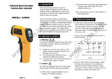
FUNCTIONAL DESCRIPTION
3
LCD
Laser
pointer
Infrared
(Fresnel)
lens &
Sensor
Battery
housing
cover
Trigger
Shift
Left
Button
2 AA batteries
Set Button
Shift Right
Button

LCD INDICATIONS AND SYMBOLS
1. Low Battery Indication
2. Measurement Icon
3. Current Reading
4. Switch Off “REF” function
5. Threshold Value Selection
6. Temperature Unit (°C/°F)
7. Reference Temperature
8. REF Icon
BUTTON FUNCTIONS
• SET button: Sets Reference Temperature, °C or °F unit and Emissivity
adjustment mode.
• Shift Left/Right Buttons: Sets Threshold values {0.5° C (1° F), 3° C (5° F)
, 5° C(10° F), OFF} and Emissivity (0.1 to 1.0).
BATTERY INSTALLATION/REPLACEMENT
To maintain reading accuracy, when the low
battery icon appears, replace thermometer’s battery.
1. Place fingers behind the battery housing cover tabs
and gently pull open the cover.
2. Pull the plastic ribbon under the batteries to pull the
batteries out.
3. Insert two fresh AA Alkaline batteries (with correct
polarity as shown by the marking on the side of
battery housing) over the plastic ribbon inside the
housing. Close the cover.
• Always purchase the correct size and grade of battery
most suitable for the intended use. Always replace
both batteries and install with correct polarity inside
thermometer.
4
PLASTIC RIBBON
HOUSING COVER
BATTERY
POLARITY
MARKING
BATTERY
COVER TAB

• Clean the battery contacts and also those of the device prior to battery installation.
• Remove batteries from equipment which is not to be used for an extended period of time.
• Remove batteries if consumed or if product is to be left unused for a long time.
OPERATING INSTRUCTIONS
Never aim the laser beam pointer at the eyes of a person or animal or
an object other than the work piece.
Follow these steps to measure surface temperature of an object in most applications. See next section for additional
measurement features.
1. Aim the thermometer at the object and squeeze the trigger for at least 3 seconds, “SCAN” icon will appear on the
display during measurement. Use the laser pointer to aim at the object more accurately.
2. Release the trigger to display the “Most Recent” temperature reading. The display will “Remain” and automatically
will shut off after Approximately 1 minute.
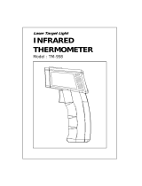
3. For accurate temperature measurement ALWAYS follow the D:S (11:1) ratio rule. For example, if the diameter
of the surface (S) is 1 ft., the distance (D) between the IR thermometer and surface should be LESS than 11 ft.
For the most accurate readings, the distance between the thermometer and the target should be 1/2 of D or
1/2 x D:S x target diameter. For our example:
Optimum Distance = 1/2 x 11 x 1ft = 5.5ft for the target diameter of 1ft.
NOTE: Temperature measurement will not be accurate off shiny objects (such as stainless
steel, gold, aluminum wrapping) or through glass or windows.
MOST ACCURATE
(TARGET > S)
LEAST ACCURATE
(TARGET < S)
LASER POINTER
S (SPOT)
TARGET
D (DISTANCE)
ACCURATE
(TARGET = S)
1/2 D
5

°C / °F TEMPERATURE UNIT SETTING
1. Briefly press the trigger to turn on the display.
2. Briefly press the SET button to toggle between °C or °F. The selected unit is saved in the thermometer memory.
REFERENCE TEMPERATURE SETTING & MEASUREMENT
Use this feature to compare the surface temperature of an object with a saved reference temperature in thermometer
memory. The comparison is visually indicated by 3 backlight colors (Blue, Green, Red) on the LCD display.
• If the scanned surface temperature is hotter than the reference temperature by more than the threshold value, the LCD
color will turn from green to red along with the fast repeating beeper sound to warn users.
• If the scanned surface temperature is colder than the reference temperature by more than the threshold value, the LCD
color will turn from green to blue along with the slow beeper sound to warn users.
• If the scanned surface temperature is within the threshold value, the LCD color will be in green,
• If Reference Temperature mode is turned off, the default LCD color is yellow.
1. Aim the thermometer at the surface spot to be used as reference temperature and press the trigger.
2. While pressing the trigger, briefly press the SET button. After appearance of the reference temperature value at the top
right corner of the LCD display and a short beep, the reference value is saved in thermometer memory.
3. Set temperature Threshold Value by pressing the shift left button “ ” or shift right button “ ” to select the
suitable threshold value from choices of 0.5°C (1°F), 3°C (5°F) , 5°C (10°F) or OFF to turn off the Reference Tem-
perature function.
4. While pressing the trigger, aim and scan various surfaces and observe the change in color of LCD display.
5. To change the reference temperature, aim at a new reference spot, press the SET button to save the new reference
temperature.
If you allow the thermometer to turn off, the saved threshold value in the memory will be erased. Repeat steps 1-4.
6
Reference Temp.
Threshold Threshold
Blue (Colder) Green (Within)
Scanned Surface Temperatures and Corresponding Display Colors
Red (Hotter)

EMISSIVITY ADJUSTMENT
Emissivity is the measure of an object’s ability to emit infrared energy. Emitted energy indicates the temperature of the
object. Emissivity can have a value from 0 (shiny mirror) to 1.0 (blackbody). An emissivity of 1.0 implies that the mate-
rial is 100% efficient at radiating energy. An emissivity of 0.1 implies that the material radiates only 10% of that which
it is capable of radiating. To compensate for deficiency of radiated energy and improve the accuracy of temperature
readings, use the Emissivity chart below to set the Emissivity of the surface which is to be scanned. To set the desired
emissivity:
1. Briefly press the trigger to turn on the display.
2. Press and hold the SET button for around 3 seconds to enter into the emissivity adjustment mode.
3. Select the emissivity value of the scanned material from the chart below.
4. Set the emissivity value by repeatedly pressing “ ” button to increase the value, or by repeatedly pressing “ ”
button to decrease the value of emissivity.
5. After setting the emissivity value, press the SET button for a few seconds to save the value in the thermometer mem-
ory and exit the emissivity adjustment mode.
Notes:
• Most organic, painted, or oxidized surfaces have emissivity values close to 0.95. The default emis-
sivity value of the thermometer is set at 0.95 which is suitable for most applications.
• Since the thermometer retains the emissivity setting in its memory, always check for emissivity to
ensure that it is either set to default (0.95) or an emissivity value corresponding to the surface to be
scanned (from Emissivity chart).
Emissivity Of Some Common Materials
Surface Material Emissivity Surface
Material
Emissivity Surface
Material
Emissivity
Aluminum Foil 0.04 Gold not polished 0.47 Paint 0.96
Aluminum Sheet 0.09 Gold polished 0.025 Paper 0.93
Aluminum Oxidized 0.2 - 0.31 Granite 0.45 Plaster, rough 0.91
Aluminum Polished 0.039 -
0.057
Gravel 0.28 Plastics 0.90 - 0.97
Aluminum Anodized 0.77 Gypsum 0.85 Polypropylene 0.97
Aluminum Rough 0.07 Ice smooth 0.966 Porcelain glazed 0.93
Asbestos board 0.96 Ice rough 0.985 PVC 0.91 - 0.93
Asbestos paper 0.93 - 0.945 Iron polished 0.14 - 0.38 Quartz glass 0.93
Asphalt 0.93 Iron, rusted red 0.61 Roofing paper 0.91
Black Body Matt 1 Iron, dark gray 0.31 Rubber, foam 0.9
7

8
Surface Material Emissivity Surface
Material
Emissivity Surface
Material
Emissivity
Black lacquer on iron 0.875 Iron, rough ingot 0.87 - 0.95 Rubber, glossy 0.94
Black Silicone Paint 0.93 Lead un-oxidized 0.057 -
0.075
Rubber, natural
hard
0.91
Black Epoxy Paint 0.89 Lead Oxidized 0.43 Salt 0.34
Black Enamel Paint 0.8 Limestone 0.90 - 0.93 Sand 0.76
Brass Dull Plate 0.22 Magnesite 0.38 Sandstone 0.59
Brass Polished 0.03 Magnesium
Polished
0.07 - 0.13 Silica 0.79
Brick, red rough 0.93 Marble White 0.95 Silicon Carbide 0.83 - 0.96
Brick, fireclay 0.75 Masonry Plas-
tered
0.93 Silver Polished 0.02 - 0.03
Carbon, not oxidized 0.81 Mercury liquid 0.1 Soil 0.90 - 0.95
Cast Iron 0.44 Mild Steel 0.20 - 0.32 Steel Oxidized 0.79
Cement 0.54 Mortar 0.87 Steel Polished 0.07
Clay 0.91 Nickel, electro-
plated
0.03 Stainless
Steel(SS)
0.85
Coal 0.8 Nickel, polished 0.072 SS, polished 0.075
Concrete 0.85 Nickel, oxidized 0.59 - 0.86 Steel Galvanized
old
0.88
Concrete, rough 0.94 Oak, planed 0.89 Steel Galvanized
New
0.23
Concrete tiles 0.63 Oil paints, all
colors
0.92 - 0.96 Tile 0.97
Cotton cloth 0.77 Paper offset 0.55 Tin un-oxidized 0.04
Copper Polished 0.023 -
0.052
Plaster 0.98 Water 0.95 - 0.963
Copper Nickel Alloy 0.059 Pine 0.84 Wood Beech,
planned
0.935
Glass smooth 0.92 - 0.94 Plaster board 0.91 Wood Oak,
planned
0.885
Glass, Pyrex 0.85 - 0.95 Porcelain, glazed 0.92 Wood, Pine 0.95

CLEANING AND STORAGE
Clean the thermometer housing and the lens using only a soft cloth or cotton swab with water or medical alcohol. Do
not let any liquid enter the case or sensor area. Allow the lens to fully dry before using the thermometer.
Avoid storing the unit in extreme temperature conditions. Do not store below -4°F, or where the radiant temperature
may exceed 140°F.
SPECIFICATIONS
Range -28°C~482°C/-20°F~900°F
Accuracy 0~482°C : ± 2°C AND -28°~0°C: ± 4°C
32~900°F : ± 4°F AND -20~32°F : ± 7°F
Resolution 0.1°C (0.1°F)
Response Time Time ≤500ms
Emissivity Adjustable 0.1~1.0
Distance To Spot(D:S) 11:1
Spectral Response 8~14um
Diode Laser Class II,Power<1mW, Wavelength 630~670nm
Auto Power Off After 60 seconds of inactivity
Operating Temp. 0°C to 50°C / 32°F to 122°F
Storage Temp. -20°C to 60°C / -4°F to 140°F
Relative Humidity(RH) 10~95%(Operating),<80%(Storage)
Power Supply 2 pc. AA battery
Battery Life Typical 65 hours continuous use
Dimensions (L*W*H) 155.5*98.8*27.5mm
Weight 185g ± 0.2g (with battery)
* IMPORTANT: Under adverse conditions (such as bright solar light outdoors or in the
surrounding environment, weak reflection of the surface to be measured, and rough surface)
measurement error can occur.
9

1 YEAR LIMITED WARRANTY
Express and Exclusive Limited Warranty to Original Retail Buyer
Every ALLTRADE® product is inspected before leaving the factory. This product is warranted to be free of defects
in material and workmanship for a period of one year from the date of original purchase. If a defect appears within
one year after the date of purchase, the purchaser may return the item, together with a purchase receipt or other
appropriate proof of purchase to the place of purchase. Upon receipt of the item(s), the place of purchase will, at its
option, replace the defective item or refund your money. This warranty shall not apply when the product has been
used for commercial or rental purposes, has been tampered with, when repairs or attempted repairs have been made
by unauthorized persons, or where the item has been subjected to misuse, abuse, accident or damage in transit. No
charges will be accepted for unauthorized parts, repairs or services.
IN NO EVENT SHALL ALLTRADE BE LIABLE FOR ANY INCIDENTAL OR CONSEQUENTIAL DAMAGES.
Some provinces do not allow limitations on how long an implied warranty lasts and some states do not allow the
exclusion or limitation of the incidental or consequential damages, so part or all of the above limitations or exclusions
may not apply to you. This warranty gives you specific legal rights, and you may also have other rights which vary
from province to province.
FCC INFORMATION
Warning: Changes or modifications to this unit not expressly approved by the party responsible for
compliance could void the user’s authority to operate the equipment.
NOTE: This equipment has been tested and found to comply with the limits for Class B digital device, pursuant to
part 15 of the FCC Rules. These limits are designed to provide reasonable protection against harmful interference in
a residential installation. This equipment generates, uses and can radiate radio frequency energy and, if not installed
and used in accordance with the instructions, may cause harmful interference to radio or television reception, which
can be determined by turning the equipment off and on, the user is encouraged to try to correct the interference by
one or more of the following measures:
- Reorient or relocate the receiving antenna.
- Increase the separation between the equipment and the receiver.
- Connect the equipment into an outlet on a circuit different from that to which the receiver is connected.
- Consult the dealer or an experienced radio/TV technician for help.
This device complies with Part 15 of the FCC Rules.
Operation is subject to the following two conditions:
(1) This device may not cause harmful interference, and
(2) This device must accept any interference received, including interference that may cause undesired operation.
10

FOR CUSTOMER SERVICE
1-800-423-3598
Printed in China
Official Licensed Product.
Vaughan is a registered trademark of
Vaughan & Bushnell Mfg. Co.
All rights reserved.
Distribution & Returns
©2017, Alltrade Tools, LLC
Reno, NV 89508
www.vaughangear.com
MADE IN CHINA
/