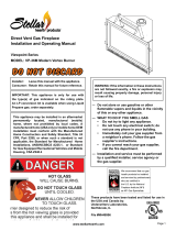
Report No. 216-F-41b-6.5
MODEL #BAY-41-G
HUSSONG MFG. CO., INC.
INSTALLATION AND OPERATION MANUAL
INSTALLER: Leave this manual with the appliance.
CONSUMER: Retain this manual for future reference.
This appliance may be installed in an
aermarket, permanently located,
manufactured home (USA only) or mobile
home, where not prohibited by local codes.
This appliance is only for use with the type of
gas indicated on the rang plate. This
appliance is not converble for use with other
gases, unless a cered kit is used.
Do not store or use gasoline or other
ammable vapors and liquids in the vicinity
of this or any other appliance.
WHAT TO DO IF YOU SMELL GAS
Do not try to light any appliance.
Do not touch any electrical switch; do not
use any phone in your building.
Immediately call gas supplier from a
neighbors phone. Follow the gas supplier
instrucons.
If you cannot reach your gas supplier, call
the re department.
Installaon and service must be performed
by a qualied installer, service agency or the
gas supplier.
WARNING: If the informaon in these
instrucons are not followed exactly, a re or
explosion may result causing property
damage, personal injury, or loss of life.
English and French installaon
manuals available through your
local dealer, or visit our website
www.kozyheat.com
A barrier designed to reduce the risk of burns from the hot viewing glass is
provided with this appliance and shall be installed.
WARNING
HOT GLASS WILL CAUSE BURNS.
DO NOT TOUCH GLASS UNTIL COOLED.
NEVER ALLOW CHILDREN TO TOUCH GLASS.
BAY-41-G ● REV-05 ● May 2014

Read this manual before installing or operating this appliance.
Please retain this owner’s manual for future reference.
CONGRATULATIONS!
We welcome you as a new owner of a Kozy Heat gas fireplace. Kozy Heat products are designed with
superior components and materials; assembled by trained craftsmen who take pride in their work. The
burner and valve assembly are 100% test-fired, and the complete fireplace is thoroughly inspected before
packaging to ensure you receive a quality product. Our commitment to quality and customer satisfaction
has remained the same for over 30 years. We offer a complete line of gas and wood fireplaces, unique
cabinets and stylish accessories to complement any décor. Adding a fireplace is one of the best ways to
increase the value of your home, and we are proud to offer a network of dealers throughout the country to
help make your experience everything you imagine. We pride ourselves in being dedicated not only to
functionality and reliability, but also customer safety. We offer our continual support and guidance to help
you achieve the maximum benefit and enjoyment from your Kozy Heat gas fireplace.
Dudley Hussong
Board Chairman
Jim Hussong
President
Homeowner Reference Information
We recommend you record the following information:
Model Name: Date purchased/installed:
Serial Number: Location on fireplace:
Dealership purchased from: Dealer Phone:
Notes:
1

TABLE OF CONTENTS
R.(# of revision) and a straight line indicates updated information.
2
R.05
HOMEOWNER REFERENCE INFORMATION
1
TABLE OF CONTENTS
2
1.0 INTRODUCTION
3
1.1
Appliance Certification
3
1.2
Safety Information
3
1.3
Commonwealth of Massachusetts Requirements
4
1.4
Installation Overview
5
2.0 SPECIFICATIONS 6
2.1
Components List
6
2.2
BTU Specifications
6
2.3
High Altitude Installations
6
2.4
Electrical Specifications
6
2.5
Gas Information
6
2.6
Appliance Dimensions
7
3.0 FRAMING AND CLEARANCES
8
3.1 Appliance Location and Installation 8
3.2 Stand-Off Assembly and Installation 8
3.3 Nailing Flange Assembly and Installation 9
3.4 Hearth Information
10
3.5 Fireplace Framing
10
3.6 Vent Termination Framing
11
4.0 TYPICAL INSTALLATION OPTIONS
12
5.0 FACING AND FINISHING
13
0
5.1
13
Mantel Requirements
5.2 Safety Barriers
14
6.0 GAS LINE CONNECTION
17
6.1 Gas Conversion
17
6.2 High Altitude Installations
17
7.0
WIRING SCHEMATICS 18
8.0
VENTING 19
8.1 Rear Vent Conversion Instructions 19
8.2 Approved Vent Systems 21
8.3 Restrictor Assembly and Installation 21
8.4 Venting for Horizontal Terminations 22
8.5 Venting for Vertical Terminations 24
8.6 Elbows 25
8.7 Horizontal and Vertical Combination Venting 25
8.8 #700-1 Series Direct Vent Termination Kit(s) 28
8.9 Termination Vent Cap Clearances 29
8.10 Vertical Vent Termination Clearances 30
12.0 LIGHTING AND SHUTDOWN
43
12.1 Operating Instructions
44
12.2 To Turn Gas Off to Appliance
44
13.0 FINALIZING THE INSTALLATION
46
13.1 Pressure Testing
46
13.2 Burner Tube Venturi Adjustment
47
13.3 Restrictors
48
14.0 TROUBLESHOOTING
49
14.1 Pilot Will Not Light / Stay Lit
49
14.2 Pilot Flame Always On / Will not Extinguish
49
14.3 Main Flame Will Not Light
49
14.4 Pilot and Burner Extinguish While in Operation
50
14.5 Glass Sooting
50
14.6 Flame Burns Blue and Lifts Off Burner
50
14.7 No Reaction to Command
50
15.0 MAINTENANCE
51
15.1 Control Board System
51
15.2 Fans
51
15.3 Vent System
51
15.4 Glass Assembly
51
16.0 REPLACEMENT PARTS LIST
52
LIMITED WARRANTY
53
LIFETIME WARRANTY
54
9.0 #970 HEAT DUCT KIT
31
9.1 Specifications
31
9.2 Attach Duct to Fireplace
31
9.3 Install Register Mounting Frame and Junction Box
32
9.4 Install and Wire Fan Assembly
32
9.5 Run and Secure Duct Pipe
33
9.6 Complete the Installation 33
9.7 Operating Instructions
33
9.8 Maintenance
33
10.0 FIREPLACE SETUP
34
10.1 Glass Frame Assembly
34
10.2 #IPI-028 Optional Fan Kit
35
10.3 Light Kit
36
10.4 Glass Media
36
10.5 Control Board Removal and Installation
37
11.0
38
CONTROL SYSTEM
11.1 Control System Components
38
11.2 Control System Operation
39

3
This appliance has been tested by OMNI-Test Laboratories located in Portland, Oregon and complies with:
ANSI Z21.88a-2012/CSA 2.33a-2012, “Vented Gas Fireplace Heaters”
CGA 2.17-M91 (R2009), “Gas-Fired Appliances for Use at High Altitudes”
CSA P.4.1-2009, “Testing Method for Measuring Annual Fireplace Efficiency”
This installation must conform with local codes, or in the absence of local codes, with the National Fuel Gas Code, ANSI
Z223.1/NFPA 54, or the Natural Gas and Propane Installation Code, CSA B149.1.
1.0 INTRODUCTION
1.1 Appliance Certification
1.2 Safety Information
Installation and repair should be done only by a qualified service person. The appliance should be inspected by a
qualified service person before use. Annual inspection by a qualified service person is required to maintain warranty.
More frequent cleaning may be required due to excessive lint from carpeting, bedding materials, etc. It is imperative
that control compartments, burners, and circulation air passageways of the appliance be kept clean.
If this appliance is installed directly on carpeting, tile, or other combustible material other than wood flooring, the
appliance shall be installed on a metal or wood panel extending the full width and depth of the appliance.
Children and adults should be alerted to the hazards of high surface temperatures and should stay away to avoid
burns or clothing ignition.
Young children should be carefully supervised when they are in the same room as the appliance. Toddlers, young
children, and others may be susceptible to accidental contact burns. A physical barrier is recommended if there are at-
risk individuals in the house. To restrict access to a fireplace or stove, install an adjustable safety gate to keep
toddlers, young children, and other at-risk individuals out of the room and away from hot surfaces.
Clothing or other flammable material should not be placed on or near the appliance.
Adequate accessibility clearances for servicing and proper operation must be maintained.
This appliance must not share, or be connected, to a chimney flue serving any other appliance.
Keep area around the appliance clear of combustible materials, gasoline, and other flammable vapor and liquids.
The flow of combustion and ventilation air must not be obstructed.
Due to high temperatures, the appliance should be located out of traffic and away from furniture and draperies.
The glass front, or any part removed for servicing the appliance, must be replaced prior to operating the appliance.
Work should be done by a qualified service technician.
Clean glass only when cool and only with non-abrasive cleansers.
WARNING: DO NOT OPERATE APPLIANCE WITH THE GLASS/FRAME ASSEMBLY REMOVED, CRACKED, OR
BROKEN. REPLACEMENT OF THE GLASS SHOULD ONLY BE PERFORMED BY A LICENSED OR
QUALIFIED SERVICE PERSON.
The glass assembly, Part #B41-057T, shall only be replaced as a complete unit, as supplied by Hussong Mfg. Co., Inc.
DO NOT SUBSTITUTE MATERIALS.
Do not strike or slam glass assembly.
A safety barrier designed to reduce the risk of burns from the hot viewing glass is provided with this appliance and
shall be installed.
Any safety screen, guard, or barrier removed for servicing the appliance must be replaced prior to operating the
appliance.
If the safety barrier becomes damaged, the barrier shall be replaced with the manufacturer’s barrier for this appliance.
For use only with the following safety barriers: part numbers #B41-BSF, #B41-FRSF, #B41-FRSF-BS, #B41-PSF, #B41-
RSF, #B41A-MSF, #B41R-CSF, or #B41R-MSF.
Under no circumstances should any solid fuel (wood, coal, paper, cardboard, etc.) be used in this appliance.
Keep burner and control compartment clean.
Do not use this fireplace if any part has been under water. Immediately call a qualified service technician to inspect
this appliance and to replace any part of the control system and any gas control which has been under water.

4
1.3.1 Installation of Carbon Monoxide Detectors
At time of installation of side wall horizontally vented gas fueled equipment, the installing plumber or gas-fitter shall observe that a hard wired
carbon monoxide detector with an alarm and battery back-up is installed on the floor level where the gas equipment is to be installed. In addition,
the installing plumber or gas-fitter shall observe that a battery operated or hard wired carbon monoxide detector is installed on each additional level
of the dwelling, building or structure served by the side wall horizontal vented gas fueled equipment. It shall be the responsibility of the property
owner to secure the services of qualified licensed professionals for the installation of hard wired carbon monoxide detectors.
In the event that the side wall horizontally vented gas fueled equipment is installed in a crawl space or attic, the hard wired carbon monoxide
detector with alarm and battery back-up may be installed on the next adjacent floor level.
In the event that the requirements of this subdivision can not be met at the time of completion of installation, the owner shall have a period of thirty
(30) days to comply with the above requirements; provided, however, that during said thirty (30) day period, a battery operated carbon monoxide
detector with an alarm shall be installed.
1.3.2 Approved Carbon Monoxide Detectors
Each carbon monoxide detector as required in accordance with the above provisions shall comply with NFPA 720 and be ANSI/UL 2034 listed and
IAS certified.
1.3.3 Signage
A metal or plastic identification plate shall be permanently mounted to the exterior of the building at a minimum of eight (8) feet above grade direct-
ly in line with the exhaust vent terminal for the horizontally vented gas fueled heating appliance or equipment. The sign shall read, in print no less
the one-half inch (1/2) in size, “GAS VENT DIRECTLY BELOW. KEEP CLEAR OF ALL OBSTRUCTIONS”.
1.3.4 Inspection
The state or local gas inspector of the side wall horizontally vented gas fueled equipment shall not approve the installation unless, upon inspec-
tion ,the inspector observes carbon monoxide detectors and signage installed in accordance with the provisions of 248 CMR 5.08 (2) (a) 1 through
4.
1.3.5 Exemptions
The following equipment is exempt from 248 CMR 5.08 (2) (a) 1 through 4:The equipment listed in Chapter 10 entitled “Equipment Not Required
To Be Vented” in the most current edition of NFPA 54 as adopted by the Board; and Product Approved side wall horizontally vented gas fueled
equipment installed in a room or structure separate from the dwelling, building or structure used in whole or in part for residential purposes.
When the manufacturer of Product Approved side wall horizontally vented gas equipment provides a venting system design or venting system
components with the equipment, the instructions provided by the manufacturer for installation of the equipment and the venting system shall
include:
Detailed instructions for the installation of the venting system design or the venting system components; and
A complete parts list for the venting system design or venting system.
When the manufacturer of Product Approved side wall horizontally vented gas equipment does not provide the parts for venting the flue gases, but
identifies “special venting systems”, the following requirements shall be satisfied by the manufacturer:
The referenced “special venting systems” instructions shall be included with the appliance or equipment installation instructions and;
The “special venting systems” shall be Product Approved by the Board, and the instructions for that system shall include a parts list and
detailed installation instructions.
A copy of all installation instructions for all Product Approved side wall horizontally vented gas fueled equipment, all venting instructions, all parts
lists for venting instructions, and/or all venting design instructions shall remain with the appliance or equipment at the completion of the installation.
Gas Equipment Venting System Provided
Gas Equipment Venting System Not Provided
1.3.6 Manufacturer Requirements
The following requirements reference various Massachusetts and national codes not contained in this manual.
For all sidewall horizontally vented gas fueled equipment installed in every dwelling, building or structure used in whole or in part for
residential purposes, including those owned or operated by the Commonwealth and where the side wall exhaust vent termination is less
than (7) feet above finished grade in the area of the venting, including but not limited to decks and porches, the following requirements
shall be satisfied:
1.3 Commonwealth of Massachusetts Requirements

5
NOTE
The qualified installer should follow the procedure best suited for the installation.
1.4 Installation Overview
1. Frame an opening for the fireplace, allowing for vent installation (top or rear) and type of installation (corner or flat wall
application). Refer 4.0, Framing and Clearances, 9.0, Venting, and 4.0, Typical Installation Options.
2. If masonry (optional) is used, prepare foundation for the masonry load. A lintel is required to support the added weight above
fireplace.
3. Attach stand-off brackets and nailing flanges to fireplace. Refer to 3.2, Stand-off Assembly and Installation, and 3.3, Nailing
Flange Assembly and Installation.
4. Insert fireplace into framing.
5. Install hearth (if applicable).
6. Complete gas line installation. Refer to 6.0, Gas Line Connection.
7. Complete electrical hook-up. Install any standard or optional electrical components at this time. Refer to 7.0, Wiring
Schematics, and 10.0, Fireplace Set Up.
8. Complete venting installation. Refer to 8.0, Venting.
9. Secure fireplace to flooring through holes in outer box bottom and to framing with nailing flanges. Verify all clearances at this
point.
10. Install facing material, mantel, or cabinetry; allowing room for safety barrier.
11. Install optional refractory / enamel panels if desired.
12. Install Light Kit and burner media. Refer to 10.3, Light Kit, and 10.4, Glass Media.
13. Install glass assembly. Refer to 10.1, Glass Frame Assembly.
14. Install safety barrier. Refer to 5.2, Safety Barriers.
15. Verify proper operation of fireplace and all components. Refer to 11.0, Control System, and 13.0, Finalizing the Installation.

6
2.2 BTU Specifications
BAY-41-G
Fuel Minimum Input BTU/hr. (kW) Maximum Input BTU/hr. (kW) Orifice Size
Natural Gas
15,000 BTU/hr (4.4 kW) 27,000 BTU/hr (7.9 kW) #42
LP Gas
13,500 BTU/hr (3.96 kW) 27,000 BTU/hr (7.9 kW) #53
2.3 High Altitude Installations
ATTENTION
USA: The appliance may be installed at higher altitudes. Please refer to your American Gas Association guidelines which state the sea
level rated input of Gas Designed Appliances installed at elevations above 2,000 ft. (610 m) is to be reduced 4% for each 1,000 ft. (305 m) above
sea level. Refer also to National Fuel Gas Code, ANSI Z223.1 / NFPA 54, local authorities, or codes which have jurisdiction in your area regarding
the de-rate guidelines.
Canada: When the appliance is installed at elevations above 4,500 ft. (1,372 m), the certified high altitude rating shall be reduced at the
rate of 4% for each additional 1,000 ft. (305 m). Refer also to CSA-B149.1 Natural Gas and Propane Installation Code, local authorities, or codes
which have jurisdiction in your area regarding the de-rate guidelines.
BAY-41-G
Fuel
Minimum Inlet
Gas Pressure
Maximum Inlet
Gas Pressure
Manifold Pressure
(High)
Manifold Pressure
(Low)
Natural Gas
5” WC (1.25 kPa)
(7” WC [1.74 kPa] recommended)
10.5” WC (2.62 kPa) 3.8” WC (.95 kPa) 1.1” WC (.27 kPa)
LP Gas
12” WC (2.99 kPa) (recommended) 13” WC (3.24 kPa) 11” WC (2.74 kPa) 2.9” WC (.72 kPa)
2.5 Gas Information
2.4 Electrical Specifications
This appliance, when installed, must be electrically grounded in accordance with local codes, or in the absence of local codes, with
the National Electrical Code, ANSI/NFPA 70, or the Canadian Electrical Code, CSA C22.1
The IFC Control System Module requires 120V of electricity / batteries to operate. Using the battery back-up will operate the
burner only. Optional fan and light components will not function on battery back-up power. Refer to 8.0, Wiring Schematics, on
page 18 for a complete electrical diagram.
2.0 SPECIFICATIONS
PART NUMBER DESCRIPTION
B41G-150 Control Board Assembly
700-203 Manual Gas Shut-off Valve
B41G-135 Burner Assembly
B41-057T Glass Frame Assembly
IPI-028 Fan Kit (2)-75 CFM
700-408 Remote Control
2.1 Components List

7
WARNING
All stand-off brackets must be attached to fireplace. Do not remove. Top stand-off brackets are not load bearing.
All clearances must be maintained. Other clearances apply.
Table 2.1 Physical Dimensions
Description
Height Width
Back
Width
Depth
Opening
Width
Opening
Height
Stand-off
Height
Back to
Top Vent
Center
Unit Top to
Center of
Back Vent
Floor to
Rear Vent
Center
Unit Top to
Back Vent
Top
Inches
34-1/2 40-3/4 21-3/4 17 37-5/8 29-5/16 10 7-1/4 6-1/8 28-3/8 2-3/4
Millimeters
876 1035 553 431 955 745 254 184 156 721 70
Figure 2.1, Appliance Dimensions
2-3/4”
(70mm)
28-3/8”
(721mm)
BACK
7-1/4”
(184mm)
21-3/4”
(553mm)
TOP
17”
(431mm)
6-1/8”
(156mm)
2-5/16”
(58mm)
FIREPLACE
FRONT
STAND-OFF
GAS LINE HOLE
ELECTRICAL
ACCESS
6-5/8”
(169mm)
6-5/8”
(169mm)
2”
(51mm)
11-13/16”
(300mm)
40-3/4”
(1035mm)
37-5/8”
(955mm)
29-5/16”
(745mm)
10”
(254mm)
34-1/2”
(876mm)
FRONT
RIGHT SIDE
LEFT SIDE
2.6 Appliance Dimensions

8
WARNING
The top stand-offs provide the 10 in. (254 mm) minimum clearance to the header. Use only non-combustible material in this area for
entire width of fireplace. Do not use wood, sheetrock, etc., in this zone.
Top stand-off brackets must be formed and attached prior to positioning fireplace into framed opening.
NOTE: Top stand-off brackets and stand-off heat shields
are attached to fireplace top in a flat state for shipping.
See Illustration 1 in Figure 3.1, Stand-Off Assembly and
Installation.
1. Remove and save (4) screws securing top stand-off heat
shield and stand-off brackets.
2. Form each top stand-off bracket by bending at
perforations, as shown in Illustration 2.
3. Align the holes in the formed top stand-offs with the holes
in the fireplace top. Secure with the (4) screws previously
removed along with (4) screws located on top of the
fireplace.
4. Form stand-off heat shields as shown in Illustration 4.
The flange on the stand-off heat shields will face up and
to the back of fireplace.
5. Align the holes in the formed stand-off heat shields with
the holes in the top stand-off brackets. Secure with (8)
screws provided in the fireplace components packet.
Figure 3.1, Stand-off Assembly and Installation
3.0 FRAMING AND CLEARANCES
3.2 Stand-off Assembly and Installation
This fireplace must be installed on a level surface capable of supporting the fireplace and venting.
Determine the exact position of your fireplace, including hearth height, width, and depth. If possible, place the fireplace in such
a manner that the vent termination will be placed between two studs, thus eliminating the need for additional framing.
This fireplace may be installed in a bedroom.
Due to high temperatures, the appliance should be located out of traffic and away from furniture and draperies.
Please be aware of the large amount of heat this fireplace will produce when determining a location.
WARNING
Install the fireplace on a hard metal or wood surface that extends the full width and depth of fireplace.
Above floor level installations: A solid, continuous platform must be constructed below the appliance.
MINIMUM PLATFORM SIZE: 40-3/4 in. (1035 mm) wide x 17 in. (431 mm) deep.
FIRE HAZARD
Do NOT install directly on carpeting, vinyl, or any combustible material other than wood.
3.1 Appliance Location and Installation
1 Top Stand-off Brackets as Shipped
Formed Stand-off
2
3 Top Stand-off Brackets Installed
4 Stand-off Heat Shields Installed
Table 3.1, Minimum Placement Clearances
To flooring 0 in. 0 mm
Appliance top to ceiling 31 in. 787 mm
Appliance side to adjacent sidewall 1 in. 25 mm
Appliance front to combustibles 36 in. 914 mm

9
Figure 3.2, Back View of Nailing Flanges
Nailing
Flanges
As
Shipped
Nailing Flanges
Installed
Stand-off
Flange
CAUTION
Never permanently remove these assemblies from the fireplace—they must be secured regardless of finish material used.
1. Remove (4) nailing flanges from the right and left side of the fireplace. See Figure 3.2, Back View of Nailing Flanges.
2. Align nailing flange with holes on outside corners of fireplace, with the stand-off flanges on the nailing flanges facing away
from the fireplace See Figure 3.2.
3. Secure the nailing flanges to the fireplace with screws (provided) through the slots in nailing flanges.
4. Bend perforation on nailing flange until parallel with fireplace face. Do not bend toward fireplace face.
5. Position framing stud against the small stand-off (located on backside of nailing flange). Secure with nails or screws. See
Figure 3.3, Front View of Set Nailing Flange
When installed, the nailing flanges provide the minimum 1/4 in. (6 mm) clearance from the sides of the fireplace to
framing. See Figure 3.4, Top View of Nailing Flange Installed.
NOTE
Depending on facing material, tabs can be adjusted forward or backward up to 1/2 in. (13 mm).
3.3 Nailing Flange Assembly and Installation
Stand-off Flange
Nailing
Flange
Framing
Stud
Figure 3.3, Front View of Set Nailing Flange
Stand-Off Flange
1/4” (6 mm) Clearance
Framing Stud
Figure 3.4, Top View of Nailing Flange Installed

10
Framing dimensions should allow for wall covering thickness and fireplace facing materials.
If using a hearth, adjust rough opening size as necessary to maintain clearance requirements.
Do not obstruct the flow of ventilation air.
Horizontal Vent Termination Framing: Refer to 3.6.2, Minimum Horizontal Vent Termination Framing Dimensions, on
page 11.
3.5 Fireplace Framing
Table 3.3, Minimum Finished Opening Dimensions
Opening Bottom to Header Height 44-1/2 in. 1130 mm
Width 41-3/8 in. 1051 mm
Depth 17-1/2 in. 445 mm
1/2 in. (13 mm) clearance at the back and the sides of the fireplace, and 1/4 in. (6.4 mm) clearance from corners must be maintained.
Figure 3.5, Finished Opening Dimensions
44 ½”
(1130mm)
41 ⅜”
(1051mm)
17 ½”
(445mm)
Table 3.2, Appliance Clearances to Combustible Framing
Top of appliance to framing 10 in. 254 mm
From appliance back 1/2 in. 13 mm
From appliance corner 1/4 in. 6 mm
Appliance top to ceiling 31 in. 787 mm
Appliance side to adjacent sidewall 1 in. 25 mm
3.5.1 Wall Enclosure Rough Opening
If masonry is to be used (optional), prepare the necessary foundation for the masonry load. When masonry construction is
being used, a lintel must be used over top of fireplace to support the added weight.
Build the hearth to desired size and height. If a hearth extension is desired, combustible material may be used.
Consider the height of hearth finish material (stone, brick, etc.) when building a fireplace platform. The bottom of the fireplace
must be level with finished hearth to allow for proper fitment of the safety barrier, except model #B41-BSF, a 1-1/4 in. (32 mm)
clearance below the fireplace for proper fitment. Refer to Table 5.2 on page 14.
3.4 Hearth Information

11
CAUTION
Cold air transfer area. The surrounding fireplace chase must comply with all clearances as outlined in this manual and be constructed in
compliance with local building codes. Outside walls should be insulated to prevent cold air from entering room.
3.6 Vent Termination Framing
WARNING
DO NOT RECESS THE VENT CAP INTO WALL OR SIDING.
IMPORTANT
Vent cap location must be in compliance with the guidelines 8.9, Termination Vent Cap Location and Clearances, on page 26.
3.6.1 Vertical Vent Terminations
Follow vent pipe manufacturer’s installation instructions for vertical vent termination framing.
A minimum of 1 in. (25 mm) clearance on all sides of the vertical vent pipe must be maintained.
3.6.2 Minimum Horizontal Vent Termination Framing Dimensions
Natural Gas & LP Gas Horizontal Venting - Rear Vent Applications
Vent Pipe Top (A) Framed Opening Top (B)
31-5/8 in. 803 mm 33-1/8 in. 842 mm
Figure 3.6, Horizontal Vent Termination
Framing Guide
IMPORTANT
Horizontal vent sections require 1/4 in. (6 mm) rise for every 12 in. (305 mm) of travel.
Follow vent pipe manufacturer’s instructions for horizontal terminations.
Table 3.4, Horizontal Venting Clearances
Vent System Top Bottom Sides
Rigid Pipe
1-1/2 in. (38 mm) 1 in. (25 mm) 1 in. (25 mm)
Flex Pipe
1 in. (25 mm) 1 in. (25 mm) 1 in. (25 mm)
Natural Gas Horizontal Venting - Top Vent Applications
90° Elbow off
Appliance Top
Vent Pipe Top (A) Framed Opening Top (B)
Rigid Vent System 45 in. 1143 mm 46-1/2 in. 1181 mm
Flex Vent System 49 in. 1245 mm 50 in. 1270 mm
LP Gas Horizontal Venting - Top Vent Applications
Minimum Vertical Rise
9 in. (229 mm)
Vent Pipe Top (A) Framed Opening Top (B)
Rigid Vent System 52-1/2 in. 1333 mm 54 in. 1372 mm
52-1/2 in. 1333 mm 53-1/2 in. 1359 mm Flex Vent System
Natural Gas & LP Gas Horizontal Venting - Top Vent Applications
Minimum Vertical Rise
15 in. (381 mm)
Vent Pipe Top (A) Framed Opening Top (B)
Rigid Vent System 57 in. 1448 mm 58-1/2 in. 1486 mm
57 in. 1448 mm 58 in. 1473 mm Flex Vent System

12
IMPORTANT
1/2 in. (13 mm) wall materials included in dimensions where applicable. Modify minimum opening if necessary to accommodate finish
material thickness.
41-3/8”
(1051mm)
41-3/8”
(1051mm)
41-3/8”
(1051mm)
28”
(711mm)
Figure 4.4, Rear Vent Vertical
Figure 4.3, Top Vent Horizontal
Figure 4.2, Top Vent Vertical
Figure 4.1, Corner
4.0 TYPICAL INSTALLATION OPTIONS

13
*
Non-Combustible Materials
ONLY in this zone.
WARNING
Provide adequate clearances around air openings into the combustion chamber.
Do not obstruct upper and lower grill openings. Room air enters through the lower passage, is then heated, and exists through upper
passage. Blocking these passages may result in overheating, creating a potentially hazardous situation.
5.0 FACING AND FINISHING
Table 5.1, Non-Combustible Zone
Rigid Pipe:
1-1/2 in. (38mm) above the elbow for the entire width and depth (behind header) of the fireplace.
#700-1 Series Flexible Venting:
1 in. (25mm) above the elbow for the entire width and depth (behind header) of the fireplace.
Provide adequate clearance in front of the fireplace to remove safety barrier, to operate lower grill, to access components, to
install gas line, and other components.
Non-combustible material may be applied over, but not attached, to the fireplace face. This will prevent non-combustible
material from falling off the fireplace face due to heat expansion.
Do not obstruct the flow of ventilation air.
Refer to Table 5.2, Safety Barrier Fit and Mounting Clearances, on page 14 for accessibility clearances. Refer to
Figures 5.2 - 5.5 on pages 14 through 16 for safety barrier models and dimensions.
5.1 Mantel Requirements
Figure 5.1, Mantel Projections, Trim Requirements, and Non-Combustible Zone
NON-COMBUSTIBLE ZONE: No materials are allowed above the fireplace within the shaded
area for the entire width and depth of the fireplace. This air space must remain open.
*
This 3/4 in. (19 mm) deep fireplace facing top trim (top facing) requires a 10 in. (254 mm)
clearance from the fireplace top.
Fireplace Top

14
5.2.2 Overlap Fit - Hanging Installation
Models #B41-BSF, #B41-FRSF-BS, #B41R-MSF, #B41R-CSF, #B41-FRSF, #B41A-MSF, #B41-PSF
1. Center the screen front over the glass frame assembly, allowing the screen front’s mounting brackets to fit inside the air
openings.
2. Align the notched tabs (located on the back) with the slots in the fireplace. Raise slightly and push back to desired position.
3. Lower the screen front until the notched tabs are firmly in position, verifying the depth accommodates finish material.
4. To remove safety screen: lift the screen up and out of slots.
Refer to Figure 5.3, Models #B41-BSF,#B41-FRSF, #B41-FRSF-BS, #B41R-CSF, and #B41R-MSF Dimensions, on page 15.
Models #B41A-MSF and #B41-PSF not shown in Figure 5.3 (Refer to Figure 5.5, Models #B41A-MSF and #B41-PSF
Dimensions, on page 16).
Model #B41-RSF
1. Locate the slots on the back side of the screen front.
2. Partially thread (4) truss head screws, included with this assembly,
into each mounting hole on the fireplace (2 each side).
3. Align the slots on the screen front with the truss head screws on
the fireplace, then slide the screen front unto fireplace.
4. Tighten all screws.
5. Fireplace accessibility: loosen, but do not remove, the (4) truss
head screws located on the sides of the fireplace. Raise the
screen up slightly and out.
5.2.1 Inside Fit - Recessed Installation
Figure 5.2, Model #B41-RSF Dimensions
37-1/2”
(953 mm)
RECTANGULAR SCREEN FRONT
(No Overlap - Inside Fit)
B41-RSF
32-1/4”
(819 mm)
5.2 Safety Barriers
Table 5.2, Safety Barrier Fit and Mounting Clearances
Models Above the fireplace Below the Fireplace Depth from Fireplace
#B41-RSF, #B41-FRSF-BS,
#B41R-MSF, #B41R-CSF,
#B41-FRSF, #B41A-MSF*,
#B41-PSF*
1/4” (6 mm)
Bottom of safety barrier must
be level with finished hearth;
except model #B41-RSF
(inside fit).
Notched tabs allow to set
screen in position to
accommodate facing
material; except model
#B41-RSF (inside fit).
#B41-BSF
1/4” (6 mm) 1-1/4” (32 mm)
#B41A-MSF*, #B41-PSF*
Depending on installation,
models have option for direct
mount. Refer to section 5.2.3.
Bottom of safety barrier must
be level with finished hearth
* Models #B41A-MSF and #B41-PSF have two installation options: (5.2.2) Hanging Installation or (5.2.3) Direct Mount
Installation Option. Follow installation instructions necessary for your type of application.

15
Figure 5.3, Models #B41-BSF,#B41-FRSF, #B41-FRSF-BS, #B41R-CSF, and #B41R-MSF Dimensions
FULL RECTANGULAR SCREEN FRONT
(Top and Sides Overlap)
B41-FRSF B41-FRSF-BS
FULL RECTANGULAR SCREEN FRONT—BRUSHED STEEL
(Top and Sides Overlap)
B41-BSF
B41R-MSF
B41R-CSF
RECTANGULAR MISSION SCREEN FRONT
(Top and Sides Overlap)

16
1. Locate the (4) acorn nuts on the left and right side of the
screen front face (2 each side).
#B41-PSF: Refer to Figure 5.4.
#B41A-MSF: The (4) acorn nuts are located at the outer
corners, closest to the edge.
2. Remove and save the (4) nuts securing the (2) mounting
brackets to the screen front.
3. Position mounting brackets to fit inside the air openings on
the sides of the fireplace, and align the (2) notched tabs on
the back of each bracket with the slots in the fireplace.
4. Set the mounting brackets into desired position, verifying
the depth accommodates finish material.
5. Secure mounting brackets with (4) truss head screws
(included) into each mounting hole on fireplace (2 each
side).
6. Slide the screen front over the (4) mounting studs and
secure with the (4) side acorn nuts previously removed.
Fireplace accessibility: remove the (4) acorn nuts on the
left and right side of the screen front face (2 each side),
then remove screen front assembly from studs on the
mounting bracket.
5.2.3 Overlap Fit - Direct Mount Installation Option
Figure 5.4, #B41-PSF Direct Mount Installation
Mounting Bracket
Mounting Stud
Figure 5.5, Models #B41A-MSF and #B41-PSF Dimensions
B41-PSF
PRAIRIE SCREEN FRONT
(Top and Sides Overlap)
B41A-MSF
Direct Mount Installation Option for Models #B41A-MSF and #B41-PSF (recommended for low clearance applications)

17
ATTENTION
In the USA: The appliance may be installed at higher altitudes. Please refer to your American Gas Association guidelines
which state: the sea level rated input of Gas Designed Appliances installed at elevations above 2,000 ft. (610 m) is to be reduced
4% for each 1,000 ft. (305 m) above sea level. Refer also to National Fuel Gas Code, ANSI Z223.1 / NFPA 54, local authorities, or
codes which have jurisdiction in your area regarding the de-rate guidelines.
In Canada: When the appliance is installed at elevations above 4,500 ft. (1,372 m), the certified high altitude rating shall
be reduced at the rate of 4% for each additional 1,000 ft. (305 m). Refer also to CSA-B149.1 Natural Gas and Propane Installation
Code, Local authorities, or codes which have jurisdiction in your area regarding the de-rate guidelines.
This fireplace is manufactured for use with Natural Gas. Follow the instructions included with the conversion kit if converting to LP
gas. (Sold separately)
ATTENTION
The conversion shall be carried out in accordance with the requirements of the provincial authorities having jurisdiction and in
accordance with the requirements of the ANSI Z223.1 installation code.
CAUTION
Installation of the gas line must only be done by a qualified person in accordance with local building codes, if any. If not, follow ANSI
223.1.
Commonwealth of Massachusetts: Installation must be done by a licensed plumber or gas fitter.
NOTE
A listed (and Commonwealth of Massachusetts approved) 1/2 in. (13 mm) tee handle manual shut-off valve and flexible gas connector
are to be connected to the 1/2 in. (13 mm) control valve inlet. If substituting for these components, please consult local codes for
compliance.
This fireplace is equipped with a 3/8” (10 mm) x 18” (457 mm) long flexible gas connector and manual shut-off valve. The gas line should
be run to the point of connection where the shut-off valve and flexible gas line will connect.
The appliance and its individual shutoff valve must be disconnected from the gas supply piping system during any pressure testing of
that system at pressures in excess of ½ psi (3.5 kPa).
The appliance must be isolated from the gas supply piping system by closing its individual manual shut-off valve during any pressure
testing of the gas line at test pressures equal to or less than ½ psi (3.5 kPa).
For high altitude installations, consult the local gas distributor or the authority having jurisdiction for proper rating methods.
IMPORTANT
The efficiency rating of this appliance is a product of thermal efficiency rating determined under continuous operating conditions and
was determined independently of any installed system.
6.0 GAS LINE CONNECTION
6.1 Gas Conversion
6.2 High Altitude Installations
Table 6.1, Inlet Gas Pressures
Fuel Minimum Inlet Gas Pressure Maximum Inlet Gas Pressure
Natural Gas
5” WC (1.25 kPa)
(7” WC [1.74 kPa] recommended)
10.5” WC (2.62 kPa)
LP Gas
12” WC (2.99 kPa) (recommended) 13” WC (3.24 kPa)

18
IMPORTANT
This system requires 120V of electricity / batteries to operate.
Figure 7.1, IFC Control Module Wiring
IFC Control Module
1.5 V type AA
1.5 V type AA
1.5 V type AA
1.5 V type AA
Flame
Sensor
SW1 Button (red)
Igniter
Pilot
Pilot
Burner
885 Proflame
Battery Pack
Main ON /OFF
Switch
Variable Speed Fan
Appliance
Ground Star
Variable Lights
Male End
7.0 WIRING SCHEMATICS

19
IMPORTANT
This appliance has outlets for both top and rear venting. The unused vent exit must have the appropriate cover plates in place and the
cover plate must be removed according to instructions from the exit to be used.
NOTE
All components removed from the fireplace rear vent will be re-installed for the top vent.
8.1 Rear Vent Conversion Instructions
8.0 VENTING
R.05
3
1. Remove the attachment screw securing the back cover plate. See Illustration 1 in Figure 8.2.
2. Remove (4) screws securing the combustion air intake cover plate. See Illustration 2.
3. Remove (6) screws securing the exhaust cover plate. See Illustration 3.
Figure 8.1, Top Vent Collar Removal
1. Remove the attachment screw securing the cover. See Illustration 1 in Figure 8.1, Top Vent Collar Removal.
2. Remove (4) screws securing the 6-5/8 in. (168 mm) combustion air intake collar. See Illustration 2.
3. Remove (6) screws securing the 4 in. (101 mm) exhaust collar. See Illustration 3.
Figure 8.2 Rear Vent Combustion Air Intake & Exhaust Collars Removal
1
1
2
3
2
8.1.1 Remove Top Vent Collars
8.1.2 Remove Back Vent Combustion Air Intake and Exhaust Collars
Page is loading ...
Page is loading ...
Page is loading ...
Page is loading ...
Page is loading ...
Page is loading ...
Page is loading ...
Page is loading ...
Page is loading ...
Page is loading ...
Page is loading ...
Page is loading ...
Page is loading ...
Page is loading ...
Page is loading ...
Page is loading ...
Page is loading ...
Page is loading ...
Page is loading ...
Page is loading ...
Page is loading ...
Page is loading ...
Page is loading ...
Page is loading ...
Page is loading ...
Page is loading ...
Page is loading ...
Page is loading ...
Page is loading ...
Page is loading ...
Page is loading ...
Page is loading ...
Page is loading ...
Page is loading ...
Page is loading ...
/