Page is loading ...

Z42 DECEMBER 2010
Z42 REV-10
www.kozyheat.com
DO NOT
DISCARD
ZERO CLEARANCE FACTORY BUILT FIREPLACE
WARNING: READ INSTRUCTIONS CAREFULLY BEFORE INSTALLATION. FAILURE TO INSTALL
THIS FIREPLACE CORRECTLY CAN CAUSE SERIOUS STRUCTURAL AND FIRE HAZARDS AND MAY
VOID YOUR WARRANTY.
INSTALLER: LEAVE THIS MANUAL WITH THE APPLIANCE.
CONSUMER: RETAIN THIS MANUAL FOR FUTURE REFERENCE.
INSTALLATION AND OPERATION MANUAL
Z-42-CD shown with accent grills

INTRODUCTION
Read this manual before installing or operating this appliance.
Please retain this owner’s manual for future reference.
PAGE 1
Homeowner Reference Information
We recommend that you record the following information about your fireplace.
Model Name:______________________________ Date purchased/installed:___________________________
Serial Number:____________________________ Location on fireplace:_______________________________
Dealership purchased from:__________________ Dealer Phone:____________________________________
Notes:_____________________________________________________________________________________
__________________________________________________________________________________________
__________________________________________________________________________________________
CONGRATULATIONS!
We welcome you as a new owner of a Kozy Heat gas fireplace. Kozy Heat products are
designed with superior components and materials and assembled by trained craftsmen who
take pride in their work. The burner and valve assembly are 100% test-fired and the complete
fireplace is thoroughly inspected before packaging to ensure that you receive a quality product.
Our commitment to quality and customer satisfaction have remained the same for over 30
years. We offer a complete line of gas and wood fireplaces, unique cabinets and stylish
accessories to compliment any décor. Adding a fireplace is one of the best ways to increase the
value of your home and we are proud to offer a network of dealers throughout the country to
help make your experience everything you imagine. We pride ourselves in being dedicated to
not only function and reliability, but customer safety as well. We offer our continual support
and guidance to help you achieve the maximum benefit and enjoyment from your Kozy Heat
gas fireplace.
Jim Hussong Dudley Hussong
President Board Chairman

TABLE OF CONTENTS
INTRODUCTION
Introduction and Homeowner Reference Information 1
TABLE OF CONTENTS
Table of Contents 2
SAFETY INFORMATION
Safety Information 3
FEATURES
Features 4
SPECIFICATIONS
Fireplace Dimensions 5
Clearance to Combustibles 5
Installation Overview 6
Placement Clearance Requirements 6
Placement Illustration 7
TYPICAL INSTALLATION OPTIONS
Typical Installation Options 8
FRAMING
Wall Enclosure Rough Opening 9
Hearth Extension 9
COMBUSTION AIR PIPE INSTALLATION
Combustion Air Pipe Installation 10
Combustion Air Pipe Venting Configurations 11
CHIMNEY
Chimney Location Illustrations 12
Chimney Requirements 13
Approved Chimney Systems 13
Anchor Plate Installation 13
Chimney Installation 14
OPTIONAL FAN INSTALLATION
Optional Fan Installation 15-16
Fan Shield Installation 15
FIREBRICK INSTALLATION
Firebrick Installation 17
PAGE 2
FIREPLACE FRAMING & FACING
Fireplace Framing & Facing 18
Mantel Projection Chart 18
COMPLETE THE INSTALLATION
Upper Grill Installation 18
Upper Grill Removal 18
Lower Grill Installation 18
Lower Grill Removal 18
Arched Door Model Spring Handle Installation 18
Cast Iron Door Model Spring Handle Installation 18
DOOR SEAL ALIGNMENT & ADJUSTMENT (Arched Door Model)
Checking the Seal 19
Hinge Adjustment 19
Latch Adjustment 20
DOOR SEAL ADJUSTMENT (Cast Door Model)
Door Seal Adjustment 21
FIREPLACE OPERATION
Fireplace Operation 22
Ash Disposal 22
MAINTENANCE REQUIREMENTS
Creosote Information 23
Glass Information 23
Broken Glass Removal & Replacement - Arched Door Model 23
Broken Glass Removal & Replacement - Cast Iron Door Model 23
OPTIONAL #970 HEAT DUCT KIT INSTALLATION
Optional #970 Heat Duct Kit Installation Instructions 24-28
ALTERNATE FLOOR PROTECTION MATERIAL WORKSHEET
Alternate Floor Protection Material Worksheet 29
TROUBLESHOOTING
Troubleshooting 30
REPLACEMENT PARTS
Replacement Parts 30

If this appliance is installed directly on carpeting, tile or other combustible material other than wood flooring, the appliance shall be
installed on a metal or wood panel extending the full width and depth of the appliance.
Combustible flooring 16” (406 mm) in front of and 8” (203mm) to each side of the fuel opening must be insulated with non-combustible
floor protection with a minimum insulation R-value of 0.8.
Do not store clothing, furniture or combustibles within 36” (914mm) of the fireplace.
The chimney should be inspected monthly during the heating season to determine if creosote buildup has occurred. If creosote has
accumulated, it should be removed to reduce the risk of a chimney fire. We recommend a professional chimney cleaner inspect and
clean the chimney at least once annually.
Children and adults should be alerted to the hazards of high surface temperatures and should stay away to avoid burns or clothing
ignition.
Young children should be carefully supervised when they are in the same room as the appliance. Toddlers, young children and others
susceptible to accidental contact burns. A physical barrier is recommended if there are at risk individuals in the house. To restrict access
to a fireplace or stove, install an adjustable safety gate to keep toddlers, young children and other at risk individuals out of the room and
away from hot surfaces.
The glass front or any part removed for servicing the appliance must be replaced prior to operating the appliance. Work should be done by
a qualified service technician.
Clean glass only when cool and only with non-abrasive cleansers.
Do not operate this appliance with the glass/frame assembly removed, cracked or broken. The glass assembly, shall only be replaced as
supplied by Hussong Mfg. Co., Inc. Replacement of the glass assembly must only be performed by a licensed or qualified service person.
DO NOT SUBSTITUTE MATERIALS.
Do not strike or slam glass assembly.
Do not burn waste paper.
Except when loading, the fireplace must be operated with the door / doors closed.
Do not obstruct room air inlet and outlet grills. This may cause the fireplace to overheat.
Burn only dry seasoned wood. Extremely hard woods, such as oak or ash can require up to two years of drying time to be sufficiently dry.
It is recommended that smoke detectors be installed in your home as required by local building codes or the authority having jurisdiction.
Some fuels, such as charcoal, may generate carbon monoxide, a dangerous, odorless gas. Exposure to carbon monoxide may cause serious
illness or death.
For further information on using your fireplace safely, obtain a copy of the National Fire Protection Association publication “Using coal &
Wood Stoves Safely.” NFPA No. HS-10
SAFETY INFORMATION
This fireplace has been tested and listed by Intertek Testing Services (Warnock Hersey) to UL 127-2008, CAN/ULC S610-M98 Safety Standards for
U.S. and Canadian installations. This fireplace installation must conform with local building codes, or in the absence of local codes, with the NFPA
211 Standard for Chimneys, Fireplaces, and Vents.
IMPORTANT: BEFORE INSTALLING THIS FIREPLACE, THE AUTHORITY HAVING JURISDICTION SHOULD BE CONSULTED TO DETERMINE
IF A PERMIT IS REQUIRED.
INSTALLATION AND REPAIR SHOULD BE PERFORMED ONLY BY A QUALIFIED INSTALLER.
WARNING: THIS FIREPLACE HAS NOT BEEN TESTED WITH ANY GAS COMPONENT. TO REDUCE THE RISK OF FIRE OR INJURY, DO NOT
INSTALL ANY GAS COMPONENT, INCLUDING AN UNVENTED GAS LOG SET INTO THIS FIREPLACE.
WARNING: DO NOT CONNECT THIS FIREPLACE TO A CHIMNEY FLUE SERVING ANOTHER APPLIANCE.
PAGE 3
MOBILE HOME INSTALLATIONS:
WARNING: DO NOT INSTALL IN A SLEEPING ROOM.
WARNING: THE STRUCTURAL INTEGRITY OF THE MOBILE HOME FLOOR, WALL, AND CEILING / ROOF MUST BE MAINTAINED.

FEATURES
EPA/WA Certified/Non-Catalytic (EPA emissions rate 3.34g / hr.)
High quality lifetime glass
Arched glass valance (Z42)
Large burning area
Air-seal 10 ga. steel door (Z42)
Twin air-seal cast iron doors (Z42-CD)
Zero Clearance to stand-offs
Air-wash system (keeps viewing area cleaner)
(2) heat duct knock-outs for optional ducting (#970 kit required)
Decorative grills in various styles and finishes
Decorative screen doors in various styles and finishes (Z42 only)
Automatic fan kit with variable speed control ( (2) 100 CFM)
44” (1118 mm) lintel iron
6” flexible heat duct kit
4” non-closure air vent
Finish material trim kits
Tested by Intertek Testing Services (formerly Warnock Hersey)
Sealed combustion chamber
EPA certified
Non-catalytic
Uses 100% outside air for combustion
U.S. and Canadian approved
Fireplace Weight (as packaged for shipment)
Z42: 515lbs. (233.6kg)
Z42-CD: 534lbs. (242.2kg)
STANDARD FEATURES
OPTIONAL FEATURES
WEIGHT
SAFETY FEATURES
PAGE 4

SPECIFICATIONS
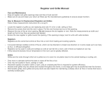
FIREPLACE DIMENSIONS
LETTER KEY A B C D E F G H
DESCRIPTION Height Width Depth Glass Frame
Height
Glass Frame
Width
Stand-off Height Front to Flue
Center
Back to Flue
Center
FIREPLACE
DIMENSIONS
INCHES 38 42 25-15/16 18-3/16 31-11/16 3-5/8 18-1/4 7-11/16
MILLIMETERS 965 1067 658 463 805 92 463 196
CLEARANCE TO COMBUSTIBLES
Fireplace to back wall……………………………….0” (0mm)
Fireplace to sidewalls………………………………..0” (0mm)
Duct boots to framing……………………………….0” (0mm)
Top stand-off to header……………………………..0” (0mm)
Fireplace bottom to inside top of enclosure……..72” (1.83m)
WITHIN ENCLOSURE AREA
EXPOSED AREA
Wallboard to faceplate top edge/ sides………….0” (0mm)
Fuel door opening to sidewall..………………..8” (203mm)
Fireplace face top to 8” (203mm) mantel…..12” (305mm)
Front of fireplace……………………………..36” (914mm)
Air duct vent to ceiling………………………….2” (51mm)
NOTE: Even though minimum clearances from back and side walls is 0”, 1/4” (6mm) space is recommended for heat expansion.
PAGE 5
B. 42”
(1067mm)
E . 31-11/16”
(805mm)
H. 7-11/16”
(196mm)
G 18-1/4”
(463mm)
7-15/16”
(202mm)
16”
(407mm)
A. 38”
(965mm)
D. 18-3/16”
(463mm)
F. 3-5/8”
(92 mm)
12-1/16”
(307mm)
16”
(406mm)
3-1/8”
(80mm)
5-7/8”
(149mm)
C. 25-15/16”
(658mm)
9-15/16”
(252mm)
Figure 5a

1. If masonry (optional) will be used, prepare foundation for the masonry load. A lintel is required to support the added weight above the
fireplace.
2. Frame an opening for the fireplace, allowing for vent installation and type of installation (corner, flat wall application).
3. Install optional hearth.
4. Install optional heat duct venting.
5. Install any electrical wiring.
6. Install fireplace into framing.
7. Attach combustion air pipe.
8. Install chimney.
9. Install desired facing material.
10. Install mantel.
11. Install optional fan.
12. Install firebrick.
13. Install door components and grills.
14. Install any optional decorative accessories.
Location of doors and windows on all floors of the home in relation to the fireplace and chimney must be considered and be in
compliance with applicable codes, if any.
This fireplace must be installed on a level surface capable of supporting the fireplace and venting.
Fireplace must be placed directly on wood or non-combustible surface (not linoleum or carpet) extending the entire depth and width of
fireplace.
Metal sealing strips must be used under fireplace and hearth extension.
The height of the enclosure must be a minimum of 72” (1.83m). This measurement is from fireplace bottom to inside top of enclosure.
Due to high surface temperatures, fireplace should be located out of traffic and away from furniture and draperies.
Please be aware of the large amount of heat this fireplace will produce when determining a location.
See illustration on following page.
INSTALLATION OVERVIEW
NOTE: The qualified installer should follow the procedure best suited for the installation.
PAGE 6
IMPORTANT: Combustible flooring 16” (406mm) in front of and 8” (203 mm) to each side of the fuel opening must be insulated with
non-combustible floor protection with a minimum insulation R-value of 0.8.
Manufactured hearth materials will usually have a published R value (resistance to heat) or k value (conductivity of heat).
Use the following formula to convert a k value to an R value.
R = 1/k x inches of thickness. See complete formula on page 29.
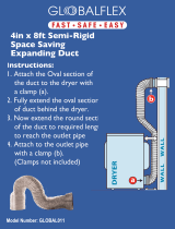
PLACEMENT CLEARANCE REQUIREMENTS

PAGE 7
PLACEMENT CLEARANCE REQUIREMENTS
Minimum enclosure height:
72” (1.83m)
Metal sealing strips
Minimum width:
48” (1219mm)
Minimum depth:
16” (406mm)
Non-combustible floor protection
with minimum
insulation R-value of 0.8
Fuel door opening
to adjacent side wall
8” (203mm)
minimum
Fireplace face top to
8” (203mm) mantel
12” (305mm)
WARNING: FOLLOW ALL INSTRUCTIONS AND CLEARANCES AS OUTLINED THROUGHOUT THIS MANUAL.
DO NOT FILL SPACE DIRECTLY ABOVE FIREPLACE WITH ANY MATERIAL (EXCEPT WOOD FRAMING).
Do not install shelving or cupboards into this area.
Figure 7a

TYPICAL INSTALLATION OPTIONS
IMPORTANT: If this fireplace is installed on an exterior wall, it must be insulated the same as any other exterior wall to prevent cold air
from entering the home.
Combustion air pipes must be secured with screws to prevent separation and cold air transfer.
NOTE: All dimensions include 1/4” (6mm) side and back expansion space /
1/2” (13mm) sheathing. Sheathing is flush with fireplace front.
Adjust dimensions if sheathing is more than 1/2” (13mm) thick.
Must allow 6” (152mm)
for combustion air pipe.
Combustion
Air Pipe
8” (203mm) from door
to side wall
Combustion
Air Pipe
Combustion
Air Pipe
21-1/2”
(546mm)
26-1/4”
(667mm)
42-1/2”
(1080mm)
26-1/4
(667mm)
48-1/2”
(1232mm)
42-1/2”
(1080 mm)
26-1/4”
(667mm)
94-3/4”
(2407mm)
67”
(1702mm)
3”
(76mm)
PAGE 8
Figure 8a

FRAMING
Frame opening to fit fireplace. All required clearances must be maintained.
MINIMUM WALL ENCLOSURE DIMENSIONS: 42-1/2” (1080mm) wide x 38-1/4” (792mm) high x 26-1/4” (667mm) deep.
IMPORTANT: Allow a minimum of 6” (152mm) in framing width dimension for the combustion air pipe which will be installed after
fireplace has been inserted into framing. Please refer to illustration on previous page.
ENCLOSURE MUST BE A MINIMUM OF 72” (1.83 m) HIGH FROM BOTTOM OF FIREPLACE TO INSIDE TOP OF ENCLOSURE.
APPLIES TO BOTH RAISED AND NON-RAISED HEARTHS: Combustible flooring 16” (406mm) in front of and 8” (203mm) to
each side of fuel door opening must be insulated with non-combustible floor protection with a minimum insulation R-value of 0.8.
Manufactured hearth materials will usually have a published R value (resistance to heat) or k value (conductivity of heat).
Use the following formula to convert a k value to an R value.
IMPORTANT: Metal sealing strip (included with fireplace) must be used. Install sealing strip so it is centered under fireplace and hearth
extension the full width of fireplace. Sand-cement grout may also be used between hearth and an on-site constructed hearth
extension.
WALL ENCLOSURE ROUGH OPENING
CAUTION: The lower grill must be allowed to open completely. Do not position fireplace in such a manner that would obstruct this grill.
NOTE: If installing optional #600-1 Fan Kit, run electrical wiring at this time.
If installing optional #970 Heat Duct Kit, please refer instructions included with kit at this time.
Floor
Non-combustible
hearth extension
material
Metal sealing strips
Sand-cement grout
PAGE 9
R = 1/k x inches of thickness. See complete formula on page 29.
Figure 9a

COMBUSTION AIR PIPE
This fireplace requires outside air for combustion and is manufactured with a collar protruding approximately 1/4” (6mm) from right side
of fireplace. An outside air pipe adaptor (4” (102mm) diameter / 3” (76mm) in length), is included with fireplace to properly connect the
outside air pipe to fireplace.
IMPORTANT: Do not connect outside air adaptor until after fireplace has been inserted into framing.
1. Insert combustion air intake adaptor into collar on right side of fireplace. Secure with screws.
2. Connect 4” (102 mm) galvanized or heavier pipe to adaptor and run to nearest outside wall. Secure with screws. See venting
configuration on following page. Aluminum flex duct pipe approved for outside combustion air may also be used.
Do not crush or tear aluminum flex duct pipe.
3. Avoid running combustion air an excessive length. Follow shortest distance possible to terminate to the outside.
WARNING: DO NOT TERMINATE INTO ATTIC OR GARAGE. TERMINATION MUST BE TO THE OUTSIDE OF HOME.
If ducting beside chimney chase, terminate intake air at least 3ft. (914m) below termination level of chimney. The air pipe may also be
ducted below floor level of fireplace providing it is ducted to the outside.
NOTE: If the combustion air pipe runs for any distance outside the enclosure, but inside the house, wrap with insulation to eliminate
condensation or frost build-up.
4. Mount a standard metal vent cover designed for 4” (102mm) pipe on outside exterior wall with louvers pointing downward.
WARNING: DO NOT USE PLASTIC FLEX PIPE, SUCH AS DRYER VENT PIPE FOR COMBUSTION AIR PIPE VENTING.
Air intake adaptor
Position fireplace into framed opening.
Insert air intake adaptor into 4” collar on
fireplace right side.
PAGE 10
DO NOT FILL THE SPACE DIRECTLY ABOVE FIREPLACE WITH ANY MATERIAL (EXCEPT WOOD FRAMING).
Do not install shelving or cupboards into this area.
Figure 10a

Do not place combustible
material below stand-offs.
Hearth Extension
Metal sealing strip centered under fireplace and
hearth the entire width of fireplace.
COMBUSTION AIR PIPE VENTING CONFIGURATIONS
PAGE 11
Figure 11a

CHIMNEY LOCATION
RECOMMENDED LOCATION
Above peak
RECOMMENDED LOCATION
Above peak
Inside heated space
MARGINAL LOCATION
Wind loading possible
MARGINAL LOCATION
Below peak
NOT RECOMMENDED
Not the highest point of roof
Wind loading possible
NOT RECOMMENDED
Too close to tree
Below adjacent structure
Lower roof line
Avoid outside wall
RECOMMENDED
Insulated exterior chase
SLANTED ROOFS
FLAT ROOFS
Chimney must
extend 3ft. (914m)
above roof
Chimney must extend 2ft. (610mm) above any
portion of the roof or adjacent structures
within 10ft. (3.05m) of chimney.
Chimney must extend 2ft. (610mm) above any
portion of the roof or adjacent structures
within 10ft. (3.05m) of chimney.
Chimney must
extend 3ft. (914m)
above roof
PAGE 12
Figure 12b
Figure 12a

CHIMNEY INSTALLATION
CHIMNEY REQUIREMENTS
MINIMUM CHIMNEY HEIGHT: 12ft. (3.66m)
Chimney must extend a minimum of 3ft. (914mm) above highest point where it passes through roof and at least 2ft. (610mm) higher
than any portion of a building within 10ft. (3.05m). See illustrations on previous page.
MAXIMUM CHIMNEY HEIGHT: 50ft. (15.24m)
ELBOWS: A maximum of (4) 30˚ elbows may be used (2 sets offsets).
MAXIMUM OFFSET: 4ft. (1219mm)
If (2) 30˚ elbows are used, chimney height must be a minimum of 14ft. (4.27m).
If (4) 30˚ elbows are used, chimney height must be a minimum of 25ft. (7.62m).
Do not connect this fireplace to a chimney flue serving another appliance.
APPROVED CHIMNEY SYSTEMS
Selkirk Metalbestos: UL (Ultra Temp)
Simpson Dura-Vent: Dura-Plus
Simpson Dura-Vent: Dura-Tech
American Metal Products: Amer-Tech
SuperPro / SuperVent
ICC / Excel
Alternate listed 6” diameter HT-type UL 103 All-Fuel Chimney Systems, including CAN-0S629 listed chimneys may be used.
Follow chimney manufacturer’s instructions for proper chimney installation, clearance to combustibles and support bracket requirements.
CAUTION: DO NOT FILL REQUIRED CLEARANCES BETWEEN CHIMNEY AND COMBUSTIBLES WITH INSULATION!
ANCHOR PLATE INSTALLATION
IMPORTANT: The appropriate anchor plate must be purchased with chosen chimney system . Sealant and screws for attaching
anchor plate to fireplace are included.
Place a bead of sealant under chimney anchor plate. Push plate collar into fireplace flue. Secure with (4) screws.
IMPORTANT: Anchor plate must fit into flue collar on fireplace to prevent creosote leakage.
Anchor Plate
Anchor Plate
Flange
Fireplace Flue
Anchor Plate
Sealant
Secure with (4) screws
PAGE 13
Figure 13a

CHIMNEY INSTALLATION
1. After anchor plate installation, connect first chimney section per manufacturer’s installation instructions.
2. Cut and frame required holes in floor, ceiling, and roof where chimney will pass through.
WARNING: REFER TO CHIMNEY MANUFACTURER‟S INSTRUCTIONS FOR PROPER FRAMING SIZE, CLEARANCE TO
COMBUSTIBLES AND SUPPORT BRACKET REQUIREMENTS.
WARNING: CLEARANCE BETWEEN CHIMNEY AND COMBUSTIBLES SHOULD NEVER BE LESS THAN 2” (51mm).
DO NOT FILL THIS REQUIRED AIR SPACE WITH INSULATION OR OTHER MATERIALS.
CHIMNEY INSTALLATION
FIRESTOP: A firestop must be installed where chimney passes through each floor level. Refer to chimney manufacturer’s instructions
for part numbers and installation procedures.
ATTIC INSULATION SHIELD: An attic insulation shield is required by chimney manufacturers for protection where the chimney
passes into attic space. This will prevent debris and insulation from coming into contact with the
chimney. Refer to chimney manufacturer requirements.
3. Install chimney sections, firestops, attic insulation shields, etc., following chimney manufacturer’s instructions and requirements,
as well as chimney minimum / maximum height requirements as outlined in this installation manual.
4. Install flashing, storm collar and chimney cap following chimney manufacturer’s instructions.
5. Refer to chimney manufacturer’s requirements concerning supports, bracing, anchors, etc.
PAGE 14
WARNING: CEILING / ROOF THIMBLE MUST EXTEND COMPLETELY THROUGH CAVITY TO OUTERMOST PLANE OF ROOF.
Figure 14a

INSTALLATION OF THIS FAN SHOULD BE DONE ONLY BY A QUALIFIED INSTALLER
The optional fan kit includes:
(2) 110 CFM fan with temperature control switch and 4ft. (1.22m) fan cord
(4) 1/4” nuts
OPTIONAL FAN INSTALLATION
IMPORTANT: Wiring must be done before enclosing fireplace sides. An electrical box and romex connector are pre-installed on a removable
panel on right side of fireplace. A receptacle / speed control assembly and (3) wire nuts are included in fireplace components
packet.
PAGE 15
Before adjusting temperature control switch, unplug 3-prong plug on fan cord from receptacle. Adjust position of temperature control
switch to a warmer location under firebox to turn fan ON sooner or move it to a cooler location under firebox to turn fan ON later. Fan will
turn on when sensor in temperature control switch reaches 110° F and will turn OFF when sensor reaches 90° F. After adjustment, plug
3-prong plug on fan cord into receptacle.
TEMPERATURE CONTROL SWITCH POSITION
FAN SHIELD INSTALLATION
Two fan shields are included in fireplace components packet.
These shields divert more air circulating through fans upward, increasing volume
exiting through upper grill.
Slide one corner of a fan shield onto front chute on each fan, making sure ‘V’
portion of shield is inside chute. Slide fan shield down onto chute.
Figure 15a
WARNING: MAKE SURE HOUSEHOLD BREAKER IS SHUT OFF PRIOR TO WORKING ON ANY ELECTRICAL LINES.
WARNING: THIS APPLIANCE IS EQUIPPED WITH A THREE-PRONG (GROUNDING) PLUG FOR PROTECTION AGAINST SHOCK HAZARD AND
SHOULD BE PLUGGED DIRECTLY INTO A PROPERLY GROUNDED THREE-PRONG RECEPTACLE. DO NOT CUT OR REMOVE
GROUNDING PRONG FROM THIS PLUG.
NOTE: Code approved line voltage wiring 14 gauge or better must be used when wiring this assembly. Refer local electrical codes for specific requirements.
NOTE: This appliance must be electrically grounded and connected in accordance with local codes, or in the absence of local codes, with the National Electrical
Code, ANSI/NFPA 70 Current Edition, or the Canadian electrical Code CSA C22.1.
NOTE: This fan will not operate unless speed control has been turned ON and sufficient heat has been applied to temperature control switch. The fan will
turn ON and OFF automatically as fireplace heats and cools. Adjust fan to desired speed while it is running.
Lower grill must be removed from fireplace prior to installation of this fan. Refer to page18 of this installation manual for assistance if
necessary.
1. Insert fans through lower grill opening, push to back. Align mounting slots in fan brackets onto mounting studs. Secure with nuts.
2. Connect fan wiring by attaching connectors on right fan onto terminals on left fan.
3. From inside lower right grill opening, loosen screws securing removable access panel (with electrical box & romex connector
installed). Remove panel.
4. Insert 110V - 120V wiring (with ground) through romex connector and wire to the speed control / receptacle assembly, matching
black (hot), white (neutral), and green (ground) wires to corresponding wires on speed control / receptacle assembly.
5. Secure speed control / receptacle assembly to the electrical box with (2) screws provided.
6. Re-install electrical access panel. Tighten screws.
7. Attach temperature control switch to bottom of firebox.
8. Plug cord into electrical box receptacle.
9. Turn speed control counter-clockwise until it ‘clicks’. This is the OFF position.
10. Turn speed control ON by turning knob clockwise past the ‘click’ - this is the highest setting.
11. Re-install lower grill. Refer to page 18 of this installation manual if necessary.
FAN INSTALLATION

PAGE 16
OPTIONAL FAN INSTALLATION
Incoming line 110-120V 60Hz
#600-083 Receptacle /Speed Control Assembly
Access panel
Electrical box
Romex Connector
White (neutral) from receptacle
White (neutral) from incoming line
Black from receptacle White from speed control
Black from speed control Black (hot) from incoming line
Ground (green) from receptacle
Connect
Connect
Ground (bare) from incoming line
Connect
Connect
Figure 16a

FIREBRICK INSTALLATION
The following firebrick are included with this fireplace:
7- 4-1/2” x 9” (114mm x 229mm)
6- 4-1/2” x 10-3/4” (114mm x 273mm)
1- 4-1/2” x 4-1/2” (114mm x 114mm)
10- 4-1/2” x 13-1/2” (114mm x 343mm)
2- 2-1/2” x 13-1/2” (64mm x 343mm)
1- Firebrick retainer
1. Position (5) 4-1/2” x 13-1/2” (114mm x 343mm) and (1) 2-1/2” x 13-1/2” (64mm x 343mm) firebrick along back wall of firebox.
2. Starting at back, position (3) 4-1/2” x 10-3/4” (114mm x 273mm) under firebrick brackets along each side of firebox.
3. Place (7) 4-1/2” x 9” (114mm x 229mm) and (1) 4-1/2” x 4-1/2” (114mm x 114mm) on firebox bottom.
4. Lay (5) 4-1/2” x 13-1/2” (114mm x 343mm) and (1) 2-1/2” x 13-1/2” (64mm x 343mm) firebrick over firebrick refractory panel
resting on (4) stainless steel pipes at top of firebox.
NOTE: The 4-1/2” x 4-1/2” (114mm x 114mm) firebrick is at center back.
5. With 45˚ flange down, slide firebrick retainer between top of first pipe & firebrick. Push retainer back until it is against front of
firebrick and under refractory panel. Set retainer down on top of pipe. The 45˚ flange on firebrick retainer should now be behind
first pipe.
Firebrick refractory panel
Firebrick refractory panel not shown in some
illustrations for clarity purposes only
PAGE 17
Firebrick refractory panel located on top of pipes. DO NOT DISCARD.
Figure 17e
Figure 17d
Figure 17c
Figure 17b Figure 17a

FIREPLACE FRAMING & FACING
Frame in fireplace. Maintain necessary clearances to combustibles. Framing materials should not come in actual contact with fireplace.
If installing a mantel (combustible material may be used), follow mantel projection chart below.
CAUTION: If using „thin‟ brick, non-combustible facing material such as rock board or metal must be used. Do not attach directly to
fireplace face.
HANDLE INSTALLATION (included with fireplace)
ARCHED DOOR: Thread black spring handle into nut located in mounting hole at top
right of door front.
CAST DOOR: Thread black spring handles onto door handles.
NOTE: Non-combustible material such as brick, tile, marble, or stone may be placed over top and side face sections.
This material MUST NOT come in direct contact with fireplace or cracking of face materials will occur.
Facing material should overlap side framing members approximately 1/4” - 3/8” (6mm - 10mm).
ARCHED DOOR MODEL
PAGE 18
A. Align rods in upper grill to holes at the top of upper grill opening. Push grill up until bottom clears face frame. Set down into holes at
bottom of grill opening.
B. Remove nuts from lower grill assembly. Insert bolts in grill through lower grill hinges. Secure with nuts.
A. Lift upper grill up and out of opening.
B. Remove nuts securing lower grill to hinges, remove grill, reattach nuts to grill.
GRILL SET (sold separately)
FINALIZE THE INSTALLATION
HOLES AT TOP OF GRILL OPENING
HOLES AT BOTTOM OF GRILL OPENING
LOWER GRILL ATTACHMENT
Figure 18c
Figure 18a
Figure 18b
INSTALL:
REMOVE:
11-1/4” (286mm)
10” (254mm)
8-1/2” (216mm)
7-1/4” (184mm)
6” (152mm)
4-1/2” (114mm)
3-1/4” (83mm)
2” (51mm)
3/4” (19mm)
17” (432mm)
Top of fireplace face
15” (381mm)
13” (330mm)
11” (279mm)
9” (229mm)
7” (178mm)
5” (127mm)
3” (76mm)
1” (25mm)

DOOR SEAL ALIGNMENT / ADJUSTMENT (Arched Door Model)
Every effort has been made at the factory to ensure a proper door seal prior to shipment. Misalignment, however, may still occur during
shipment, mishandling and / or installation.
The following procedures will help you determine if the door is sealing properly, and how to achieve a proper seal.
CHECKING THE SEAL
1. Close and latch door.
2. Check seal by pushing against corners of glass.
- No movement indicates proper seal.
- Any movement between the glass and firebox face at any corner indicates an inadequate seal. This will create creosote build-up
on glass and cause the fire to burn faster.
HINGE ADJUSTMENT
1. Close and latch door.
2. Place wooden shim (included) between bottom of door and the face on the latch side. This is necessary to ‘hold’ door in horizontal
alignment.
3. Determine if upper, lower, or both hinges need adjustment.
IMPORTANT: DO NOT LOOSEN NUTS SECURING DOOR HINGES AT TOP AND BOTTOM OF DOOR.
UPPER FACE HINGE: Remove upper grill. Locate two nuts securing upper face hinge.
LOWER FACE HINGE: Open lower grill, locate two nuts securing lower face hinge (similar to upper grill hinge).
4. Using a 7/16 wrench or nut driver, LOOSEN BUT DO NOT REMOVE the two nuts. Push door in slightly, (either top or bottom,
depending on adjustment needed) to achieve a tighter door seal. Re-tighten nuts.
5. Remove shim. Repeat steps #1 & #2 in ‘CHECKING THE SEAL‟ section above.
6. Repeat steps #1 - #5 of this section until proper door seal is achieved.
NOTE: Door may need to be „pulled out‟ if binding occurs at either the top or bottom right corners.
Do not loosen these nuts
Loosen nuts securing face hinge
Place shim between bottom of
door and face
PAGE 19
Figure 19a
/