GE JGGN24LPDBB Installation guide
- Category
- Barbecues & grills
- Type
- Installation guide
This manual is also suitable for
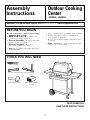
GE JGGN24LPDBB gas grill offers a versatile outdoor cooking experience with its durable construction and convenient features. Equipped with a side burner, you can simultaneously grill your main course and prepare sauces or sides. The Flav-R-Wave cooking system enhances the flavor of your food, while the retractable shelf provides extra space for grilling tools or platters. Enjoy precise temperature control with the infinite control burner system, ensuring perfectly cooked meals every time.
GE JGGN24LPDBB gas grill offers a versatile outdoor cooking experience with its durable construction and convenient features. Equipped with a side burner, you can simultaneously grill your main course and prepare sauces or sides. The Flav-R-Wave cooking system enhances the flavor of your food, while the retractable shelf provides extra space for grilling tools or platters. Enjoy precise temperature control with the infinite control burner system, ensuring perfectly cooked meals every time.


-
 1
1
-
 2
2
-
 3
3
-
 4
4
-
 5
5
-
 6
6
-
 7
7
-
 8
8
-
 9
9
-
 10
10
-
 11
11
-
 12
12
-
 13
13
-
 14
14
-
 15
15
-
 16
16


GE JGGN24LPDBB Installation guide
- Category
- Barbecues & grills
- Type
- Installation guide
- This manual is also suitable for
GE JGGN24LPDBB gas grill offers a versatile outdoor cooking experience with its durable construction and convenient features. Equipped with a side burner, you can simultaneously grill your main course and prepare sauces or sides. The Flav-R-Wave cooking system enhances the flavor of your food, while the retractable shelf provides extra space for grilling tools or platters. Enjoy precise temperature control with the infinite control burner system, ensuring perfectly cooked meals every time.
Ask a question and I''ll find the answer in the document
Finding information in a document is now easier with AI
Related papers
Other documents
-
 Furniture of America IDF-AC6330GY Installation guide
-
Alvin Mobile Step-Design File Tube Rack WSF36 User manual
-
 airmaster 70005 User manual
-
 NewTechWood US-QD-PB-13-TK Installation guide
-
Luxor LLTS12 Assembly Manual
-
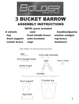 Bolder Innovations BB2RM Operating instructions
-
Broil King 9459-34 Installation guide
-
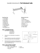 Grace Company The Professional Caddy Operating instructions
-
DataVideo RKM-572 User manual
-
Broilmaster DPA155 Heat Indicator s Installation guide


