Page is loading ...

Multimaster 260
MIG/TIG/STICK WELDING PACKAGE
F15-692-G 06 / 2009
INSTRUCTION MANUAL
This manual provides instructions for units starting with serial No. MORJ125051

2
This equipment will perform in conformity with the description thereof contained in this manual and accompa-
nying labels and/or inserts when installed, operated, maintained and repaired in accordance with the instruc-
tions provided. This equipment must be checked periodically. Malfunctioning or poorly maintained equipment
should not be used. Parts that are broken, missing, worn, distorted or contaminated should be replaced imme-
diately. Should such repair or replacement become necessary, the manufacturer recommends that a telephone
or written request for service advice be made to the Authorized Distributor from whom it was purchased.
This equipment or any of its parts should not be altered without the prior written approval of the manufacturer.
The user of this equipment shall have the sole responsibility for any malfunction which results from improper
use, faulty maintenance, damage, improper repair or alteration by anyone other than the manufacturer or a ser-
vice facility designated by the manufacturer.
BE SURE THIS INFORMATION REACHES THE OPERATOR.
YOU CAN GET EXTRA COPIES THROUGH YOUR SUPPLIER.
These INSTRUCTIONS are for experienced operators. If you are not fully familiar with the
principles of operation and safe practices for arc welding and cutting equipment, we urge
you to read our booklet, “Precautions and Safe Practices for Arc Welding, Cutting, and
Gouging,” Form 52-529. Do NOT permit untrained persons to install, operate, or maintain
this equipment. Do NOT attempt to install or operate this equipment until you have read
and fully understand these instructions. If you do not fully understand these instructions,
contact your supplier for further information. Be sure to read the Safety Precautions be-
fore installing or operating this equipment.
CAUTION
USER RESPONSIBILITY
READ AND UNDERSTAND THE INSTRUCTION MANUAL BEFORE INSTALLING OR OPERATING.
PROTECT YOURSELF AND OTHERS!

3
TABLE OF CONTENTS
Section / Title Page
1.0 Safety Precautions ....................................................................................5
1.1 Safety - English ..................................................................................5
1.2 Safety - Spanish .................................................................................9
1.3 Safety - French .................................................................................13
2.0 Description ..........................................................................................17
2.1 General ........................................................................................19
2.2 Receiving - Handling............................................................................19
2.3 Safety ..........................................................................................19
2.4 Description.....................................................................................19
3.0 Installation.......................................................................................... 23
3.1 Location....................................................................................... 23
3.2 Handle Assembly Installation................................................................... 23
3.3 Electrical Input Connections ....................................................................24
3.4 Voltage Changeover ............................................................................24
3.5 Secondary Output Connections . . . . . . . . . . . . . . . . . . . . . . . . . . . . . . . . . . . . . . . . . . . . . . . . . . . . . . . . . . . . . . . . 25
3.6 “NAS” Torch Connections ...................................................................... 26
3.7 Wire Feeder Mechanism ....................................................................... 26
3.8 Connection of Shielding Gas Supply .............................................................27
4.0 Operation .......................................................................................... 29
4.1 Standard Controls ............................................................................. 29
4.2 Optional Controls...............................................................................31
4.3 Mig Welding Set-up.............................................................................33
4.4 Tig Welding Set-up .............................................................................35
4.5 Stick Welding Set-up ........................................................................... 36
4.6 Handling the Tig Torch..........................................................................37
5.0 Maintenance........................................................................................ 39
5.1 Maintenance and Service ...................................................................... 39
5.2 Inspection and Service......................................................................... 39
6.0 Replacement Parts ...................................................................................41
6.1 General ........................................................................................41
6.2 Ordering .......................................................................................41

4
TABLE OF CONTENTS

5
SECTION 1 SAFETY PRECAUTIONS
1.0 Safety Precautions
1.1 Safety - English
WARNING: These Safety Precautions are
for your protection. They summarize pre-
cautionary information from the references
listed in Additional Safety Information sec-
tion. Before performing any installation or operating
procedures, be sure to read and follow the safety precau-
tions listed below as well as all other manuals, material
safety data sheets, labels, etc. Failure to observe Safety
Precautions can result in injury or death.
PROTECT YOURSELF AND OTHERS --
Some welding, cutting, and gouging
processes are noisy and require ear
protection. The arc, like the sun, emits
ultraviolet (UV) and other radiation
and can injure skin and eyes. Hot metal can cause
burns. Training in the proper use of the processes
and equipment is essential to prevent accidents.
Therefore:
1. Always wear safety glasses with side shields in any
work area, even if welding helmets, face shields, and
goggles are also required.
2. Use a face shield tted with the correct lter and
cover plates to protect your eyes, face, neck, and
ears from sparks and rays of the arc when operating
or observing operations. Warn bystanders not to
watch the arc and not to expose themselves to the
rays of the electric-arc or hot metal.
3. Wear ameproof gauntlet type gloves, heavy long-
sleeve shirt, cuess trousers, high-topped shoes,
and a welding helmet or cap for hair protection, to
protect against arc rays and hot sparks or hot metal.
A ameproof apron may also be desirable as protec-
tion against radiated heat and sparks.
4. Hot sparks or metal can lodge in rolled up sleeves,
trouser cus, or pockets. Sleeves and collars should
be kept buttoned, and open pockets eliminated from
the front of clothing.
5. Protect other personnel from arc rays and hot
sparks with a suitable non-ammable partition or
curtains.
6. Use goggles over safety glasses when chipping slag
or grinding. Chipped slag may be hot and can y far.
Bystanders should also wear goggles over safety
glasses.
FIRES AND EXPLOSIONS -- Heat from
ames and arcs can start res. Hot
slag or sparks can also cause res and
explosions. Therefore:
1. Remove all combustible materials well away from
the work area or cover the materials with a protec-
tive non-ammable covering. Combustible materials
include wood, cloth, sawdust, liquid and gas fuels,
solvents, paints and coatings, paper, etc.
2. Hot sparks or hot metal can fall through cracks or
crevices in oors or wall openings and cause a hid-
den smoldering re or res on the oor below. Make
certain that such openings are protected from hot
sparks and metal.“
3. Do not weld, cut or perform other hot work until the
workpiece has been completely cleaned so that there
are no substances on the workpiece which might
produce ammable or toxic vapors. Do not do hot
work on closed containers. They may explode.
4. Have re extinguishing equipment handy for instant
use, such as a garden hose, water pail, sand bucket,
or portable re extinguisher. Be sure you are trained
in its use.
5. Do not use equipment beyond its ratings. For ex-
ample, overloaded welding cable can overheat and
create a re hazard.
6. After completing operations, inspect the work area
to make certain there are no hot sparks or hot metal
which could cause a later re. Use re watchers when
necessary.
7. For additional information, refer to NFPA Standard
51B, "Fire Prevention in Use of Cutting and Welding
Processes", available from the National Fire Protec-
tion Association, Batterymarch Park, Quincy, MA
02269.
ELECTRICAL SHOCK -- Contact with
live electrical parts and ground can
cause severe injury or death. DO NOT
use AC welding current in damp areas,
if movement is conned, or if there is
danger of falling.

6
SECTION 1 SAFETY PRECAUTIONS
1. Be sure the power source frame (chassis) is con-
nected to the ground system of the input power.
2. Connect the workpiece to a good electrical
ground.
3. Connect the work cable to the workpiece. A poor
or missing connection can expose you or others
to a fatal shock.
4. Use well-maintained equipment. Replace worn or
damaged cables.
5. Keep everything dry, including clothing, work
area, cables, torch/electrode holder, and power
source.
6. Make sure that all parts of your body are insulated
from work and from ground.
7. Do not stand directly on metal or the earth while
working in tight quarters or a damp area; stand
on dry boards or an insulating platform and wear
rubber-soled shoes.
8. Put on dry, hole-free gloves before turning on the
power.
9. Turn o the power before removing your gloves.
10. Refer to ANSI/ASC Standard Z49.1 (listed on
next page) for specic grounding recommenda-
tions. Do not mistake the work lead for a ground
cable.
ELECTRIC AND MAGNETIC FIELDS
— May be dangerous. Electric cur-
rent owing through any conduc-
tor causes localized Electric and
Magnetic Fields (EMF). Welding and
cutting current creates EMF around welding cables
and welding machines. Therefore:
1. Welders having pacemakers should consult their
physician before welding. EMF may interfere with
some pacemakers.
2. Exposure to EMF may have other health eects which
are unknown.
3. Welders should use the following procedures to
minimize exposure to EMF:
A. Route the electrode and work cables together.
Secure them with tape when possible.
B. Never coil the torch or work cable around your
body.
C. Do not place your body between the torch and
work cables. Route cables on the same side of
your body.
D. Connect the work cable to the workpiece as close
as possible to the area being welded.
E. Keep welding power source and cables as far
away from your body as possible.
FUMES AND GASES -- Fumes and
gases, can cause discomfort or harm,
particularly in conned spaces. Do
not breathe fumes and gases. Shield-
ing gases can cause asphyxiation.
Therefore:
1. Always provide adequate ventilation in the work area
by natural or mechanical means. Do not weld, cut, or
gouge on materials such as galvanized steel, stain-
less steel, copper, zinc, lead, beryllium, or cadmium
unless positive mechanical ventilation is provided.
Do not breathe fumes from these materials.
2. Do not operate near degreasing and spraying opera-
tions. The heat or arc rays can react with chlorinated
hydrocarbon vapors to form phosgene, a highly
toxic gas, and other irritant gases.
3. If you develop momentary eye, nose, or throat ir-
ritation while operating, this is an indication that
ventilation is not adequate. Stop work and take
necessary steps to improve ventilation in the work
area. Do not continue to operate if physical discom-
fort persists.
4. Refer to ANSI/ASC Standard Z49.1 (see listing below)
for specic ventilation recommendations.

7
SECTION 1 SAFETY PRECAUTIONS
5. WARNING: This product, when used for welding
or cutting, produces fumes or gases
which contain chemicals known to
the State of California to cause birth
defects and, in some cases, cancer.
(California Health & Safety Code
§25249.5 et seq.)
CYLINDER HANDLING -- Cylinders,
if mishandled, can rupture and vio-
lently release gas. Sudden rupture
of cylinder, valve, or relief device can
injure or kill. Therefore:
1. Use the proper gas for the process and use the
proper pressure reducing regulator designed to
operate from the compressed gas cylinder. Do not
use adaptors. Maintain hoses and ttings in good
condition. Follow manufacturer's operating instruc-
tions for mounting regulator to a compressed gas
cylinder.
2. Always secure cylinders in an upright position by
chain or strap to suitable hand trucks, undercar-
riages, benches, walls, post, or racks. Never secure
cylinders to work tables or xtures where they may
become part of an electrical circuit.
3. When not in use, keep cylinder valves closed. Have
valve protection cap in place if regulator is not con-
nected. Secure and move cylinders by using suitable
hand trucks. Avoid rough handling of cylinders.
4. Locate cylinders away from heat, sparks, and ames.
Never strike an arc on a cylinder.
5. For additional information, refer to CGA Standard P-1,
"Precautions for Safe Handling of Compressed Gases
in Cylinders", which is available from Compressed
Gas Association, 1235 Jeerson Davis Highway,
Arlington, VA 22202.
EQUIPMENT MAINTENANCE -- Faulty or
improperly maintained equipment can
cause injury or death. Therefore:
1. Always have qualied personnel perform the instal-
lation, troubleshooting, and maintenance work.
Do not perform any electrical work unless you are
qualied to perform such work.
2. Before performing any maintenance work inside a
power source, disconnect the power source from
the incoming electrical power.
3. Maintain cables, grounding wire, connections, power
cord, and power supply in safe working order. Do
not operate any equipment in faulty condition.
4. Do not abuse any equipment or accessories. Keep
equipment away from heat sources such as furnaces,
wet conditions such as water puddles, oil or grease,
corrosive atmospheres and inclement weather.
5. Keep all safety devices and cabinet covers in position
and in good repair.
6. Use equipment only for its intended purpose. Do
not modify it in any manner.
ADDITIONAL SAFETY INFORMATION -- For
more information on safe practices for
electric arc welding and cutting equip-
ment, ask your supplier for a copy of
"Precautions and Safe Practices for Arc
Welding, Cutting and Gouging", Form
52-529.
The following publications, which are available from
the American Welding Society, 550 N.W. LeJuene Road,
Miami, FL 33126, are recommended to you:
1. ANSI/ASC Z49.1 - "Safety in Welding and Cutting"
2. AWS C5.1 - "Recommended Practices for Plasma Arc
Welding"
3. AWS C5.2 - "Recommended Practices for Plasma Arc
Cutting"
4. AWS C5.3 - "Recommended Practices for Air Carbon
Arc Gouging and Cutting"

8
SECTION 1 SAFETY PRECAUTIONS
5. AWS C5.5 - "Recommended Practices for Gas Tung-
sten Arc Welding“
6. AWS C5.6 - "Recommended Practices for Gas Metal
Arc Welding"“
7. AWS SP - "Safe Practices" - Reprint, Welding Hand-
book.
8. ANSI/AWS F4.1, "Recommended Safe Practices for
Welding and Cutting of Containers That Have Held
Hazardous Substances."
MEANING OF SYMBOLS - As used
throughout this manual: Means Atten-
tion! Be Alert! Your safety is involved.
Means immediate hazards which,
if not avoided, will result in im-
mediate, serious personal injury
or loss of life.
Means potential hazards which
could result in personal injury or
loss of life.
Means hazards which could result
in minor personal injury.

17
Specications
Rated DCCV or DCCC Output (10 min base)
50% duty cycle (NEMA Class I) ..................................260 amps @ 27 vdc
Output Current Range
Mig (GMAW) ................................................................................. 35-300 amps
Tig (GTAW) .................................................................................... 10-300 amps
Stick (SMAW)................................................................................ 40-300 amps
Open Circuit Voltage
Mig (MGAW)...........................................................................................39.0 vdc
Tig (TGAW).................................................................................................20 vdc
Stick (SMAW).............................................................................................70 vdc
Primary Input Voltage & Current @ 260 amp rated load
208/230 vac, 60 Hz, 1 ph .................................................................57/52 amps
Wire Feed Range ..............................................65-675 ipm (1.6 - 17.3 m/min)
Net Weight ................................................................................250 lbs. (112.5 kg)
Shipping Weight .....................................................................290 lbs. (130.5 kg)
W x L x H ...................25.3 in. (64 cm) x 39.5 in. (100 cm) x 33.5 in. (85 cm)
Advanced SuperSwitch•
TM
technology makes
multi-process welding a breeze. Simplied
setup makes it easy to select Mig, Tig, or Stick
DC welding output from 15 to 300 amps; rated •
260 amps at 50% duty cycle
Output Pre-Set Capability for Quick Set-Up•
Two Digital Meters for Easy Fine Tuning•
Heavy Duty Four Drive Roll Stand•
Convenient, Large Capacity Built-In Tool Box •
Dual “Easy-On” Cylinder Tray•
Pulse Mig Capability with optional module•
Industrial Ready-To-Weld Multi-Process Package Multimaster 260
Ordering Information
Multimaster 260 cvcc Multi-Process Packages
Each of the following packages are set ready to run .035/.045 diameter
wire. Packages include power source with built-in four roll wire feeder;
factory installed undercarriage & cylinder rack; Gun Master 250 Amp
Mig Torch; Gas regulator/owmeter with hose; Work cable & clamp;
Primary input cable; Mig Welding Handbook; 10# sample of .035 86HP
III Wire and 5# sample Stick Electrodes. See next page for options and
accessories.
MultiMaster 260 w/ 12 ft. GM-250 “NAS” torch
208/230 vac, 1 phase 50/60 Hz Argon ................................. 0558001519
208/230 vac, 1 phase 50/50 Hz CO
2
...................................... 0558001523
230-575 vac, 1 phase 50/60 Hz Argon ................................. 0558001521
230-575 vac, 1 phase 50/60 Hz CO
2
...................................... 0558001525
MultiMaster 260 w/ 15 ft. GM-250 “NAS” torch
208/230 vac, 1 phase 50/60 Hz Argon ................................. 0558001520
208/230 vac, 1 phase 50/60 Hz CO
2
...................................... 0558001524
230-575 vac, 1 phase 50/60 Hz Argon ................................. 0558001522
230-575 vac, 1 phase 50/60 Hz CO
2
..................................... 0558001526
MultiMaster 260 w/ 12 ft. “NAS” torch and spool gun, Argon
208/230 vac, 1 phase 50/60 Hz /MT-250SG ....................... 0558001767
230-575 vac, 1 phase 50/60 Hz /MT-250SG ...................... 0558001768
MultiMaster 260 w/ 15 ft. “NAS” torch and spool gun, Argon
208/230 vac, 1 phase 50/60 Hz /MT-250SG ....................... 0558001769
230-575 vac, 1 phase 50/60 Hz /MT-250SG ....................... 0558001770
MultiMaster 260 w/ 12 ft. GM-250 “NAS” torch and spool gun, Argon
208/230 vac, 1 phase 50/60 Hz /ST-23A .............................. 0558001771
230-575 vac, 1 phase 50/60 Hz /ST-23A .............................. 0558001772
MultiMaster 260 w/ 15 ft. “NAS” torch and spool gun, Argon
208/230 vac, 1 phase 50/60 Hz /ST-23A .............................. 0558001773
230-575 vac, 1 phase 50/60 Hz /ST-23A .............................. 0558001774
SECTION 2 DESCRIPTION

18
Optional Equipment
Pre/Post Flow/Spot/Burnback module ..................................... 0558002889
Inductance Control Module ......................................................... 0558002888
Remote Control Module ................................................................ 0558002605
FC-5B Foot Control - 30 ft. (9.1 m) cable
Provides remote current control and contactor (on/o) control .................33646
Spool Gun Module ........................................................................... 0558002606
MT-250SG Spool Gun ..................................................................................36779
(Requires Spool Gun module)
ST-23A Spool Gun .........................................................................................19164
(Requires adapter 37301 and Spool Gun module)
Pulse Module Option ...................................................................... 0558002604
HW-17V-2TL (w/valve) Heliarc Tig Torch Assembly
Tig weld without disconnecting the Mig torch. 60 deg. 12.5 ft. .................35857
HW-17 Torch Accessory Kit ..................................................................... 999126
Work Cable & Clamp .....................................................................................35881
Digital Meter
Volts, Amps, and Wire feed speed
Voltage/Current
Control
Process Selector
Voltage Preset
Status Indicators
Wire Feed Speed
Control
Pulse Module Option
Pulse Mig Welding of Carbon Steel, Stainless
Steel and Aluminum
Remote Control Option
“Spool-on-Gun” Option
Electrode Holder Assembly - 175 amp (15 ft.)
Includes holder, cable and quick connector ..................................... 0558001786
Electrode Holder Assembly - 300 Amp (15 ft.)
Includes holder, cable and quick connector ..................................................21226
Tee Connector (1 male/ 2 female) ................................................... 13792804
Primary Extension Cord (25 ft.) .................................................................37833
TIG Welding Handbook ............................................................................ 781F29
MIG Welding Handbook ........................................................................... 791F18
SECTION 2 DESCRIPTION

19
2.1 GENERAL
This manual has been prepared for experienced welders. Do
NOT permit untrained persons to install, operate or maintain
this equipment. Do NOT attempt to install or operate this
equipment until you have read and fully understand these
instructions.
This manual is intended for use in familiarizing person nel with
the design and operation of this equipment. All information
presented here should be read careful ly before installing and
using this equipment.
2.2 RECEIVING-HANDLING
Upon receipt of this equipment, clean all packing material
from around the unit and immediately inspect for any dam-
age that may have occurred during shipment. Any claims
for loss or damage occurring in transit must be led with
the carrier. The carrier will furnish a copy of the bill of lading
and the freight bill on request, if the need to le a damage
claim arises.
When requesting information regarding this equipment,
make sure that you include product name, part num ber, and
serial number.
2.3 SAFETY
The safety section at the front of this manual should be read
completely before attempting to install and operate this
equipment. Both equipment and person nel hazards are
reduced if proper safety precautions are taken. If you are
unsure of yourself in any situa tion, ask your supervisor or
other experi enced person nel for help.
2.4.1 POWER SOURCE
The power source is a secondary chopper DC output designed
for single phase primary connec tions. An output controlled
fan provides proper cooling during normal welding opera-
tions and shuts o four minutes after welding stops. The fan
will automatically re-start when welding resumes and proper
machine temperatures will be maintained.
2.4.2 WIRE FEEDER
The four (4) roll drive wire feeder is built into the power source
cabinet, housed separately from the welding machine electri-
cal components. Cooling air is not drawn through the wire
feeder compartment or electronic controls reducing exposure
to dirt and dust which improves product performance and
reliability.
The wire feeder pushes wire at speeds from 65 to 675 ipm
(inches per minute).
2.4.3 CONTROLS
The Multimaster 260 can be used to weld solid and ux cored
wires. The operator selects the process desired on a three posi-
tion switch located on the front panel. A detailed description
of the power source controls is included in Section 4 (Opera-
tion) of this manual.
2.4.4 BUILT-IN TOOL BOX
The Multimaster 260 is designed with a lockable storage space
on the left side of the machine for welding accessories such as
contact tips, gas nozzles, small grinder, spare parts, welding
hood and protective clothing. (Figure 1B)
2.4.5 GUN MASTER 250 MIG GUN
This air-cooled welding gun is supplied complete and ready
to weld .035 in. hard wire. The gun accommodates .045 inch
wire by changing the contact tip. Other wire sizes can be used.
Refer to Section 6, for other wire size and alloy accessories.
2.4.6 RUNNING GEAR
The Multimaster 260 is equipped with running gear with swivel
front wheels and a dual gas cylinder support.
Means immediate hazards which, if not
avoided, will result in immediate, serious
personal injury or loss of life.
Means potential hazards which could result
in personal injury or loss of life.
Means hazards which could result in minor
personal injury.
2.4 DESCRIPTION
The Multimaster 260 is a DC welding system designed for
Mig (GMAW), Tig (GTAW) or Stick (SMAW) welding. In the Mig
mode this unit is capable of operating with short arc or spray
arc transfer and handles both solid wires and tubular cored
wires. This unit is suitable for carbon steel, stainless steel,
aluminum and many other alloys. It provides a power source
with built in wire feeder and undercarriage with provisions
for two gas cylinders.
SECTION 2 DESCRIPTION

20
Choice of 12’ or 15’ Gun
Master 250 Mig Gun
HW-17 Tig Torch
(Optional)
Stick Electrode
Holder
(Optional)
15’ Work Cable
and Clamp
Choice of Argon or CO
2
Regulator/
Flowmeter
Simple To Use Weld
Controls
Figure 1A - Components
Welding Gloves
(Optional)
Eyetech Auto-
matic Helmet
(Optional)
Factory Installed
Two Cylinder Easy
Load Running Gear
Large, Easy To Read
Digital Displays for Wire
Speed, Amps and Volts
6’ Gas Hose
Simple and quick
polarity change-over
Cylinder Safety
Chain
SECTION 2 DESCRIPTION

21
Tool Box with Small
Parts Tray
Voltage Switch
Compartment
4 Roll
Drive Stand
2 Cylinder
Low Mount Tray
Wheel Kit
Installed
Handle
Hinged Wire
Compartment Door
Adaptable
Spindle Assembly
Inductance Burnback
Preow/postow
Spot (Options)
Figure 1B - Components
Cylinder
Chain
SECTION 2 DESCRIPTION

23
3.0 INSTALLATION
3.1 LOCATION
Several factors should be considered when selecting an in-
stallation site. Adequate ventilation is necessary to provide
cooling, and the amount of dirt and dust to which the ma-
chine is exposed should be minimized. There should be at
least 18 inches of unrestricted space between the machine’s
side and rear panels and the nearest obstruction to provide
freedom of air movement through the power source.
3.2 HANDLE ASSEMBLY INSTALLATION
The Multimaster 260 is factory assembled except for the front
handle assembly which is mounted to the machine upside
down for shipping purposes. The handle assembly consists
of two brackets and a cross bar. To install the handle in its
proper position, do the following:
A. Remove the two sheet metal screws from the brackets on
each side of the front handle assembly. See Figure 3A.
B. Remove front handle assembly and reverse sides with the
mounting brackets. This will put the handle assembly in
the proper orientation. Reattach brackets using the sheet
metal screws removed in Step A. See Figure 3B.
Figure 2 - Dimensions
20”
32”
42”
Sheet metal Screws
The installation site should permit easy removal of the ma-
chine’s outer enclosure for maintenance. Installing or placing
any type of ltering device will restrict the volume of intake
air, thus subjecting the internal components to overheating.
Warranty is void if any type of ltering device is used.
Figure 3B - Handle Assembly Installation
SECTION 3 INSTALLATION
Sheet metal
Screws
Figure 3A - Handle Assembly Removal
Handle Bracket
Handle Bracket

24
3.3 ELECTRICAL INPUT CONNECTIONS
In order to provide a safe and convenient means to complete-
ly remove all electrical power from the machine, it is highly
recommended that a line disconnect switch be installed in
the input circuit of the machine.
Before making electrical input connections to the weld-
ing machine, unplug the unit or use “Machinery Lockout
Procedures”. If the connections are to be made from a line
disconnect switch, the switch should be padlocked in the
o position. If the connection is to be made from a fuse-
box, remove the fuses and padlock the cover closed.
3.3.1 INPUT ELECTRICAL REQUIREMENTS
The primary input voltage requirements are shown on the
power source nameplate. The power source is designed
to be operated from 208/230 vac single phase 50/60 Hz or
230/460/575 vac single phase 50/60 Hz.
3.3.2 INPUT PLUG
The input power cord is provided with an attachment plug.
The plug will mate with a 250 volt, 50 Amp receptacle conform-
ing to NEMA 6-50R congura tion (208/230 vac model only).
The receptacle should be wired to a separately fused discon-
nect or circuit breaker by an electrician. This disconnect
or breaker can be wired to a single phase system or two
conductors of a three phase system. A third conductor for
grounding must be connected between the disconnect and
the receptacle.
The termi nal labeled GRD is connected to the power source
chassis and is for ground purposes only. This must be
connected to a good electrical ground. Do not connect
a conductor from the terminal labeled GRD to any one of
the L1, L2 terminals as this will result in an electrically hot
machine chassis.
3.4 VOLTAGE CHANGEOVER (Figure 4)
The voltage changeover terminal board is located in the tool
compartment on the left side of the machine. As shipped
from the factory, the Multimaster 260 is congured for the
highest connectable voltage. If using the other input voltages,
the links on the terminal board (TB) inside the unit must be
repositioned for the appropriate input voltage. See gures
4A - 4E for 60Hz input voltage congurations. To gain access
to the terminal board, open the access panel on the left side.
To change voltages, perform the following:
Typical Installation - User
Supplied Power Discon-
nect Box, Receptacle and
Plug
SECTION 3 INSTALLATION
Primary
Input
Volts
Full
Load
Line
Amperes
Fuse
Size
Recommended
Primary
Input
Conductor
Size
Ground
Conductor
Size
208 57 90 8 8
230 52 90 8 8
460 26 30 12 12
575 20 30 12 12
Input Conductor and Fuse Size

25
Figure 4 - Voltage Changeover Terminal Board
208/230 Version Shown Installed
Clear Panel Hinges on
corner screw
Remove this
screw only
This screw must
remain in place
Do Not Remove
Figure 4A -
Input Terminal Board
230/460/575 Vac Model
230 Vac Conguration
Figure 4B -
Input Terminal Board
230/460/575 Vac Model
460 Vac Conguration
Figure 4C -
Input Terminal Board
230/460/575 Vac Model
575 Vac Conguration
Figure 4D -
Input Terminal Board
208/230 Vac Model
208 Vac Conguration
Figure 4E -
Input Terminal Board
208/230 Vac Model
230 Vac Conguration
A. Remove the left screw ONLY and swing plexiglass door
upward.
B. Adjust the copper bar links to the primary voltage being
used.
C. Swing clear panel down and secure with screw.
3.5 SECONDARY OUTPUT CONNEC TIONS (Figure 5)
The Multimaster 260 Welding System is completely self-
contained so that the front panel gun/torch connections are
internally connected to the welding polarity (DCEP or DCEN)
via the secondary output terminals depending on the welding
process being used.
Figure 5 - Polarity Set-up
SECTION 3 INSTALLATION

26
3.6 “NAS” TORCH CONNECTIONS (Figure 6)
To install a Gun Master Mig Gun 250, remove the locking knob
on the side of the NAS connector and insert the male power
pin of the gun. Be sure the “O” rings are securely seated by
pushing inward on the power pin while tightening the lock-
ing knob.
Install a spool of welding wire on the spindle as follows:
A. Remove the locking pin from the spindle (Figure 8).
B. Place wire spool on the spindle to rotate clockwise as
wire is unwound; spindle brake pin must engage hole in
spool.
C. Replace the locking pin into the spindle hole closest to
the spool.
3.7.3 THREADING WELDING WIRE
A. Turn o power switch.
B. Release pressure drive roll assembly. Check that proper
wire diameter grooves are in the inner position.
3.7 WIRE FEEDER MECHANISM
3.7.1 DRIVE ROLLS (Figure 7 and 9)
The drive roll has two grooves: the small groove feeds .035 in.
diameter wire, the large groove feeds .045 in. wire. The groove
nearest the gear motor feeds the wire. If the required groove
is not correctly positioned, perform the following:
A. Release the pressure drive roll lever.
B. Remove the two (2) screws holding the drive rolls to the
gears.
C. Reverse the drive roll on the drive roll shaft.
D. Replace the screws and tighten.
E. Secure the pressure drive roll assembly.
Figure 6 - NAS Gun Connector
Locking Knob
Feed Roll Release Screws
Figure 7 - Wire Feeder Mechanism
3.7.2 WELDING WIRE SPOOL INSTALLATION
As with any work area, make sure safety glasses with side
shields are worn when handling or changing wire or clip-
ping wire o at the spool or at the end of the torch. Hold
onto the wire coming o the spool with one hand before
clipping. Serious eye injury can result due to the resilience
of the wire which can quickly unravel, or a cut wire end
which may shoot across the room.
Figure 8 - Spindle Assembly
Locking Pin
Spool Spindle
SECTION 3 INSTALLATION

27
Pressure Roll Assembly
Pressure Release
Lever
Threading the wire
through the inlet
guide
Figure 9 - Threading the Wire
Before threading welding wire, make sure chisel point and
burrs have been removed from wire end to prevent wire
from jamming in gun or liner.
C. Feed the wire from the spool through the inlet guide,
across the drive roll grooves and center guide into the
outlet guide and NAS connection tube.
SECTION 3 INSTALLATION
Make sure that the proper “outlet guide tube” is inserted into
the front-panel gun tting for the size and type of wire being
used, see Table 6 in the Replacement Parts section for wire
feed accessories.
To ensure proper wire feeding, it is important that the wire be
kept clean and that the drive rolls be periodi cally cleaned of
any chips or scale that might be carried into the gun liner.
D. Lower pressure roll assembly and secure. Turn the power
“on” and feed wire through to gun tip using the gun trig-
ger to start wire feeding.
When the power switch is on, and gun trigger is de-
pressed, the electrode wire becomes electrically hot, and
the wire drive rolls will rotate.
3.7.4 SPOOL BRAKE DRAG ADJUSTMENT
Spool brake disc friction should provide enough drag to keep
the wire spool from spinning freely after wire feed stops. If
adjustment is required, turn the adjusting screw inside the
spindle housing clockwise to increase drag or counterclock-
wise to decrease it. Drag should be just enough to limit
wire overrun.
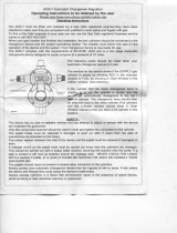
3.8 CONNECTION OF SHIELDING GAS SUPPLY
3.8.1 R-33-FM-580 Regulator
The R-33-FM-580 regulator is an adjustable regulator designed
for use with Argon, Helium, and C-25 (75% Argon/25% CO
2
)
gas service. Table 2 provides the recommended ow ranges
for the R-33-FM-580 regulator.
Argon 10-50 cfh
Helium 150-230 cfh
C-25 10-50 cfh
Table 2 - Typical Flow Rates
A. With the cylinder cap in place, CAREFULLY slide the cylinder
of gas onto the Multimaster 260 cylinder rack.
B. Secure the cylinder to the unit using the chain provid-
ed.
C. Unscrew the cylinder cap.
Do not clamp regulator cap in a vise or grip it with a pair
of pliers. Distortion of cap can jam the internal parts and
cause excessively high delivery pressure as well as weaken
the threaded joint to the regulator body. This may cause
the cap to y o and possibly injure personnel in area.
D. Open the cylinder valve slightly, for an instant, to blow
out any dust or dirt that may have collected in the valve
outlet. BE SURE to keep your face away from the valve
outlet to protect your eyes.
E. Attach the regulator to the cylinder valve. Align the regula-
tor so that the owmeter is vertical and then tighten the
connection nut with a 1-1/8 in. open end or adjustable
wrench. To prevent damaging the O-ring seals and plastic
tube, do not use the owmeter tube as a ‘handle’ when
attaching the regulator.
F. Close the ow control valve on the owmeter.
G. Attach the gas hose from the rear of the Multimaster 260
to the regulator outlet connection.

28
Figure 10 - R-33 Regulator
Cylinder Valve
Connection
Nut
Flow Tube
Control Valve
Pressure
Gauge
SECTION 3 INSTALLATION
Never stand directly in front of or behind the regulator
when opening the cylinder valve. Always stand to one
side.
H. Open the cylinder valve SLOWLY a fraction of a turn. This
will prevent damage to the gauge and critical components
in the regulator. When the gauge needle stops moving,
then open the cylinder valve fully.
I. Using a leak test solution, such as P/N 998771 (8 oz. ctr)
or soapy water, test for leakage around the cylinder valve
stem, the regulator inlet connection, and the hose con-
nections at the regulator. Correct any leaks before starting
work.
3.8.1 TO REGULATE FLOW
Flow is controlled by adjusting the owmeter valve until de-
sired ow is indicated by the ball oat in the owmeter tube.
Always take the reading across the TOP of the ball.

29
4.0 OPERATION
Comply with all ventilation, re and other safety require-
ments for arc welding as established in the SAFETY Section
at the front of this manual.
4.1 STANDARD CONTROLS
4.1.1 POWER ON/OFF SWITCH & LAMP
The main power switch is located on the front panel in the
upper left-hand corner. This switch energizes the main trans-
former, control circuitry and illuminates the Power “ON” lamp.
(Figures 12 &13)
4.1.2 FAULT LAMP (Figure 12)
The fault lamp is congured for future use and is not currently
activated.
4.1.3 TEMP LAMP (Figure 12)
The TEMP lamp illuminates if an over temperature condition
occurs within the Multimaster 260. This condition may be
caused by excessive duty cycle or over-current conditions.
When an over temperature condition occurs, the welding
output is turned o and the unit must be allowed to cool.
The machine will automatically reset when the temperature
falls to a safe level.
4.1.4 PROCESS SELECTOR SWITCH (Figure 12)
The three position process selector switch is located in the
upper righthand corner of the control panel. The process
selector switch provides the visual indication of which process
(Mig, Tig or Stick) has been selected.
4.1.5 SECONDARY WELDING CONNECTIONS
The secondary output welding terminals, POS (+) and NEG
(-) are located in the lower right of the front panel, directly
beneath the NAS Mig Gun Connector (Figure 13). See 4.4, 4.5,
and 4.6 for Setup Guides for specic application.
4.1.6 DIGITAL DISPLAYS (WFS, AMPS & VOLTS)
The digital displays located on the left side of the control
panel are multi-functional depending on the welding process
being used.
4.1.7 MIG WELDING
In the Mig process mode, the digital displays will read preset
wire feed speed in inches per minute and preset arc volts
when the PRESET button is pressed. Once welding begins,
the displays will show average welding current and volts in
the top and bottom display, respectively. The displays have
a “HOLD” circuit that retains the welding conditions. After
welding stops, the display will continue to show the last
welding current and voltage sampled for 10 seconds, then
returns to “0”.
Figure 11 - Burnback Control
4.1.8 TIG and STICK WELDING
In the TIG and STICK process mode, you must depress and hold
the PRESET button while presetting the welding current in the
top display. Releasing the preset button causes the display to
return to zero. Once welding begins, the display will show av-
erage welding current and volts in the top and bottom display,
respectively. After welding stops, the display will again return
to zero. There is no “HOLD” circuit for the display when using
the TIG and STICK process modes.
4.1.9 WIRE FEED SPEED CONTROL (Figure 12)
The wire feed speed control potentiometer allows wire feed
speed adjustments between 65 and 675 inches per minute
(IPM). Selecting the Mig process and pressing the PRESET
switch allows the wire feed speed to be preset in the top digital
display by turning the wire speed knob.
4.1.10 VOLTAGE/CURRENT TRIM (Figure 12)
The arc voltage is controlled with this knob when the Process
Selector Switch is in the MIG position. The Mig arc voltage
can be preset by pressing the preset button and reading the
preset arc volts in the bottom digital display while turning
this knob.
The arc current is controlled with this knob when the WELD
PROCESS SWITCH is in the TIG or STICK position. The welding
current can be preset in amperes by pressing the preset button
and reading the preset amps in the top digital display while
turning this knob. The actual arc voltage will be displayed
during welding.
4.1.11 BURNBACK CONTROL (Figure 11)
The burnback control is located inside the wire spool compart-
ment above the wire feed motor. The control knob adjusts
the time between when the wire feed brake is applied and
the welding contactor is turned “o”. This determines how far
the wire will burnback towards the contact tip after welding
is stopped. If the wire is sticking in the weld pool then turn
the knob clockwise a small amount and retest. Continue this
procedure until the wire clears the top of the weld pool or
burns back the desired amount.
SECTION 4 OPERATION
/