Page is loading ...

Challenger Series
OPERATORS MANUAL
Manual No. 513562 Rev.2


This manual provides basic information about the machine. Instructions and suggestions are
given covering its operation and care.
The illustrations and specifi cations are not binding in detail. We reserve the right to make
changes to the machine without notice, and without incurring any obligation to modify or pro-
vide new parts for machines built prior to date of change.
DO NOT ATTEMPT to operate the machine until instructions and safety precautions in this
manual are read completely and are thoroughly understood. If problems develop or questions
arise in connection with installation, operation, or servicing of the machine, contact Stoelting.
Stoelting Foodservice Equipment
502 Highway 67
Kiel, WI 53042-1600
U.S.A.
Main Tel: 800.558.5807
Fax: 920.894.7029
Customer Service: 888.429.5920
Fax: 800.545.0662
Email: [email protected]
© 2014 PW Stoelting, LLC
stoeltingfoodservice.com

Safety Alert Symbol:
This symbol Indicates danger, warning or caution.
Attention is required in order to avoid serious per-
sonal injury. The message that follows the symbol
contains important information about safety.
Signal Word:
Signal words are distinctive words used throughout
this manual that alert the reader to the existence and
relative degree of a hazard.
CAUTION
The signal word “CAUTION” indicates a potentially
hazardous situation, which, if not avoided, may result
in minor or moderate injury and equipment/property
damage.
A Few Words About Safety
Safety Information
Read and understand the entire manual before
operating or maintaining Stoelting equipment.
This manual provides the operator with information
for the safe operation and maintenance of Stoelting
equipment. As with any machine, there are hazards
associated with their operation. For this reason safety
is emphasized throughout the manual. To highlight
specifi c safety information, the following safety defi ni-
tions are provided to assist the reader.
The purpose of safety symbols is to attract your at-
tention to possible dangers. The safety symbols, and
their explanations, deserve your careful attention
and understanding. The safety warnings do not by
themselves eliminate any danger. The instructions
or warnings they give are not substitutes for proper
accident prevention measures.
If you need to replace a part, use genuine Stoelting
parts with the correct part number or an equivalent
part. We strongly recommend that you do not use
replacement parts of inferior quality.
WARNING
The signal word “WARNING” indicates a potentially
hazardous situation, which, if not avoided, may result
in death or serious injury and equipment/property
damage.
CAUTION
The signal word “CAUTION” not preceded by the
safety alert symbol indicates a potentially hazardous
situation, which, if not avoided, may result in equip-
ment/property damage.
NOTE (or NOTICE)
The signal word “NOTICE” indicates information or
procedures that relate directly or indirectly to the
safety of personnel or equipment/property.

TABLE OF CONTENTS
SECTION 1 - DESCRIPTION AND SPECIFICATIONS
1.1 Description ......................................................................................................................1
1.2 Specifications ..................................................................................................................1
SECTION 2 - INSTALLATION
2.1 Shipment and Transit........................................................................................................3
2.2 Installation ........................................................................................................................3
2.3 Remote Condenser ..........................................................................................................5
2.4 Mix Pump Installation and Checkout (Remote Models)...................................................... 7
SECTION 3 - OPERATING INSTRUCTIONS
3.1 Safety Information............................................................................................................. 9
3.2 Safety Precautions ...........................................................................................................10
3.3 Operating Controls ...........................................................................................................11
3.4 Spigot Switch...................................................................................................................11
3.5 Drive Motor Overload .......................................................................................................11
3.6 Power Switch (CLEAN-OFF-SERVE) ..............................................................................11
3.7 Freezing Switch................................................................................................................11
3.8 Door Interlock Switch........................................................................................................11
3.9 Remote Pump Switch.......................................................................................................11
3.10 Dispense Rate Adjuster .................................................................................................11
3.11 High Pressure Cut Out ....................................................................................................11
3.12 Sanitizing Procedures .................................................................................................... 11
3.13 Initial Freeze Down and Operation..................................................................................12
3.14 Removing Mix From the Freezer.....................................................................................13
3.15 Disassembly and Assembly of Front Door (Model 217 and 238R) ..................................14
3.16 Disassembly and Assembly of Auger ............................................................................. 16
3.17 Disassembly and Assembly of Mix Line Adaptor (Remote Models) ................................17
3.18 O-Ring Removal and Care .............................................................................................17
3.19 Cleaning of Freezer and Freezer Parts...........................................................................17
3.20 Sanitize Freezer Parts....................................................................................................18
SECTION 4 - MAINTENANCE INSTRUCTIONS
4.1 Freezer Adjustments ........................................................................................................19
4.2 Product Temperature Adjustment ......................................................................................19
4.3 Drive Belt Tension Adjustment ..........................................................................................19
4.4 Condenser Cleaning (Air-Cooled Freezers) .....................................................................19
4.5 Preventative Maintenance ................................................................................................20
4.6 Extended Storage ............................................................................................................20
4.7 Troubleshooting ................................................................................................................20
SECTION 5 - HOW TO ORDER REPLACEMENT PARTS
5.1 How To Order Replacement Parts ....................................................................................23
5.2 Parts List and Reference Drawings ..................................................................................23

LIST OF ILLUSTRATIONS
Figure Title Page
1 Caster Options ...................................................................................................... 3
2 Water Connections ................................................................................................ 4
3 Electrical Connections........................................................................................... 4
4 Auger Shaft Rotation ............................................................................................. 5
5 Remote Condenser ............................................................................................... 6
6 Mix Transfer Line & Pump Installation .................................................................... 8
7 Warning Label Locations....................................................................................... 10
8 Operating Controls ................................................................................................ 11
9 Air Bleed............................................................................................................... 12
10 Pump Switch ......................................................................................................... 12
11 Front Door Disassembly........................................................................................ 14
12 Spinner Assembly ................................................................................................. 15
13 Auger with Rubber Rear Seal ................................................................................ 16
14 Auger Disassembly ............................................................................................... 16
15 Plastic Parts.......................................................................................................... 16
16 Auger Assembly.................................................................................................... 16
17 Auger Flight Spring ............................................................................................... 17
18 Mix Line Adapter ................................................................................................... 17
19 Removing O-rings ................................................................................................. 17
20 Potentiometer........................................................................................................ 19
21 Belt Adjustment ..................................................................................................... 19

1
SECTION 1
DESCRIPTION AND SPECIFICATIONS
1.1 DESCRIPTION
The Stoelting Challenger pressurized freezers are available in water cooled or air cooled versions (completely self-
contained or with remote condensers). Some models are available with built-in hoppers or remote mix pump feed.
Freezers are equipped with fully automatic controls to provide for consistent temperature and uniformity of product.
Refer to Mix Pump Manual for complete information on the operation of the mix pump.
1.2 SPECIFICATIONS
LEDOM NOITPIRCSED
712elytSpmuPreppoH-evreStfoS-lerraBelgniS
R712elytSpmuPetomeR-evreStfoS-lerraBniwT
R522elytSpmu
PetomeR-ekahS-rennipShtiwlerraBelgniS
R832elytSpmuPetomeR-evreStfoS-tsiwThtiwlerraBniwT
-fleS.rosserpmoc
ekahsPH0.2dnaevrestfosPH5.2ahtiw,rotomevirdPH2aedulcnisledomevobaehT
.pmupxim912ledomgnitleotSahtiw,ed
isrepreppoh)retil7.42(nollag5.6evahsrezeerfdeniatnoc
LEDOM
HTDIW
mc/ni
HTPED
mc/ni
THGIEH
mc/ni
.TWTEN
gk/bl
71283/515.99/52.93361/52.467.381/504
R71283/515.99/52.935.451/57.061.071/573
R52283/515.99/52.935.451/5
7.065.471/583
R8326.04/617.99/52.933.451/57.06223/017
:STNEMERIUQERLACIRTCELE
.elbaliavaeraztreh06,stlov032/802,esahp3rotlov032,esahP1-citsemoD
.stnemeriuqercificepsrofrezeerfehtforaerehttaetalpemanlacirtceleotrefeR-
.lenapredaehtnorfro,lenapedistfeldnihebdet
acoltekcapnoitamrofninisimargaidgniriW-

2

3
SECTION 2
INSTALLATION
2.1 SHIPMENT AND TRANSIT
The freezer has been assembled, operated, and inspected
at the factory. For shipment, the freezer is placed on skids,
with small parts placed separately in boxes. Upon arrival
at the final destination, the freezer must be checked for
any damage which may have occurred during final transit.
With the sturdy packaging used, the equipment should
arrive in satisfactory condition. THE CARRIER IS RE-
SPONSIBLE FOR ALL DAMAGE IN TRANSIT, WHETHER
VISIBLE OR CONCEALED. Do not pay the freight bill until
you have checked the equipment. Have the carrier note
any visible damage on the freight bill. If concealed dam-
age and or shortage is found later advise the carrier within
ten days and request inspection. The customer must place
claim for damage and/or shortages in shipment with the
carrier. Stoelting, Inc. cannot make any claims against
the carrier.
2.2 INSTALLATION
Installation of the freezer involves moving the freezer close
to its permanent location, removing all protective packag-
ing, setting in place and cleaning.
A. Remove all protective packaging. Remove the hold
down bolts from the wooden pallet, and walk freezer
off the pallet.
B. The freezer is shipped without legs. To install legs,
lift freezer and screw caster, extension, or leg into
the bottom of frame at each corner. Refer to caster
and leg options in Figure 1.
Figure 1. Caster Options
For Models 217, 217R, 225R, 238R
Warning
FREEZER MUST NOT BE ALLOWED TO TIP
MORE THAN 10°. FAILURE TO HEED THIS WARN-
ING COULD RESULT IN THE FREEZER FALLING
ON IT’S SIDE CAUSING SERIOUS DAMAGE OR
INJURY.
C. To level turn the top part of the caster or the bottom
part of the leg in or out. Then level by placing a level
on top of the freezer at each corner.
NOTE
Leveling is necessary for correct freezer drainage.
D. For all freezers allow a minimum of 6 inches of space
at the front and rear for air circulation. For efficient
operation, the room temperature should not be be
low 60° F (16° C) or above 90° F (32° C).
E. For water cooled freezers, install a minimum of 1/2
inch pipe or 5/8 inch inside diameter copper water
line to the freezer. The water line must be connected
in a manner that will comply with local codes and
allow adequate room for servicing.
NOTE
All external plumbing is to be supplied by the customer.
Water lines connect to fittings at the rear of the freezer.
(See Fig.2) Connect the clean, potable, water inlet to water
source using flexible high water pressure line. Ordinary
garden hose is not recommended. Connect the water out-
let to flexible plastic tubing. The outlet can be secured to
floor drain, as the outlet is clean, warm water.
Option B - Casters & ExtensionsOption A - Casters

4
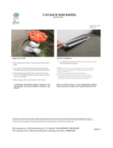
Figure 2
Water Connections
Figure 3
Electrical Connections
Water Out
Water In
Access Holes

5
CAUTION
FLUSH ALL WATER LINES BEFORE INSTALLA-
TION. IN NEW STORES WITH SEDIMENT IN
WATER, ADD SUITABLE FILTER OR STRAINER
TO WATER INLET. FAILURE TO FLUSH ALL
WATER LINES MAY RESULT IN EQUIPMENT
FAILURE AND EQUIPMENT DAMAGE.
F. Refer to nameplate at the side of the freezer for
specific electrical requirements. Connect electrical
power to the junction box at the rear of the freezer.
Bring wires into junction box through access hole in
bottom rear of freezer. (Fig.3).
ATTENTION
The 24V AC pilot circuit is wired for a 240V supply.
If this freezer is installed in a location with a 208V
supply the transformer must be rewired. Remove
the left and right side panel to access.
CAUTION
ELECTRICAL TECHNICIANS MUST BE CONTINU-
OUSLY ALERT TO THE PRACTICE OF ALL NEC-
ESSARY SAFETY RULES AND PRECAUTIONS
WHEN SERVICING THIS EQUIPMENT AS VOLT-
AGES ARE PRESENT WHICH CAN CAUSE SERI-
OUS OR FATAL INJURY.
ELECTRICAL WIRING MATERIALS, ARRANGE-
MENT AND GROUNDING MUST CONFORM WITH
NATIONAL AND OTHER APPLICABLE ELECTRI-
CAL CODES.
Figure 4
Auger Shaft Rotation
G. Check the auger shaft rotation by placing the MAIN
DRIVE switch in the CLEAN position. Auger shaft
rotation is clockwise as viewed through the clear plas-
tic front door. If the rotation is not clockwise, turn
main electrical power OFF. Then reverse any two
electrical power lines in the junction box (three phase
only). Recheck auger shaft rotation. (Fig.4)
NOTE
Three phase freezers in areas of unbalanced elec-
trical loads require special attention when connect-
ing input electrical power. The unbalanced leg of
power (called wild or high) must be connected to L2
in the junction box.
H. Remote fed freezers require an approved 1/2 inch
(12.7 mm) I.D. refrigerated mix transfer tube from
mix pump in walk in cooler to mix inlet at top of
freezer. Clamp both ends of tubing. Support to
prevent sagging and to promote total drainage when
not in use.
NOTE
Refer to the mix pump manual for complete infor-
mation on the operation of the mix pump.
2.3 REMOTE CONDENSER
The remote condenser can be installed either indoors or
outdoors without additional protection required. Horizon-
tal installation requires the liquid line connection to be
made at the bottom of the coil. There should be no ob-
structions to the fan within five feet of the discharge.
NOTE
There must be an adequate supply of ambient air
below 120° F (49° C). Operating above this tem-
perature will result in loss of capacity. Guard against
recirculation due to discharge into an overhang roof
or the side of the building.
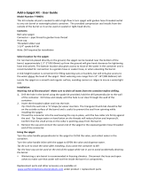
A. Connect 230VAC, 60HZ, 1-PH to run the 1/6 HP,
2.8 AMP fan motor.
B. Connect refrigerant lines. Use 3/8 inch (9.52 cm)O.D.
copper line only. Trap hot gas line as shown (Fig.5).
Do not trap liquid line at all. If condenser is below
the freezer, no traps are required. (Fig.5)
NOTE
Maximum line length is 50 feet (15.24 meters).

6
Figure 5
Remote Condenser

7
2.4 U3 MIX PUMP INSTALLATION AND CHECKOUT
(REMOTE MODELS)
A. Follow the steps below to install the mix pump in an
upright position on the wall (allow clearance for a
mix container under pump). See Fig.6.
1. Mount by locating four (4) hole centers on cooler
wall using mounting bracket as template.
Caution
KNOW THE COOLER’S WALL DESIGN BEFORE
DRILLING TO PREVENT PERSONAL INJURY OR
PROPERTY DAMAGE.
2. Drill four (4) 1/2" diameter holes into cooler wall
3/4" deep.
3. Insert well-nut to flange and apply silicone seal-
ant around outside diameter of flange and cooler
wall.
4. Repeat steps 2&3 for other located hole centers.
5. Mount bracket to cooler wall with supplied wing
screws. Hand tighten until secure.
6. Mount pump to bracket with wing nuts.
B. Connect 1/2" (1.27cm) I.D. plastic food grade tubing
to the mix container. Secure with hose clamps. (5/
8" tubing is used with the 219 pump)
C. Connect 1/2" (1.27 cm) I.D. plastic food grade
tubing between the large port of air/mix tee and
refrigerated mix transfer line. Secure with large hose
clamp or equivalent.
D. Plug mix pump into a 115 volt grounded receptacle.
National sanitation foundation compliance require-
ments (Remote Pump)
In order to comply with the “National Sanitation Testing
Laboratory, Inc.” (NSF)code #6:
A. This unit (remote pump) must be installed with a “NSF”
listed refrigerated mix transfer line. The mix transfer
line must be pitched to the cooler with no sags or
low points, to allow complete drainage.(Fig.6).
B. The product at the mix pump and in transfer line must
be maintained below 41° F (5.0° C).

8
Figure 6
Mix Transfer Line
and Pump Installation

9
3.1 Safety Information
WARNING Read and understand the entire manual before operating or maintaining Stoelting equipment.
This Owner’s Manual provides the operator with information for the safe operation and maintenance of Stoelting
equipment. As with any machine, there are hazards associated with their operation. For this reason safety is
emphasized throughout the manual. To highlight specific safety information, the following safety definitions are
provided to assist the reader.
The purpose of safety symbols is to attract your attention to possible dangers. The safety symbols, and their
explanations, deserve your careful attention and understanding. The safety warnings do not by themselves eliminate
any danger. The instructions or warnings they give are not substitutes for proper accident prevention measures.
Safety Labels
Take notice of all warning labels on the freezer (refer to Figure 7). The labels have been put there to help you
maintain a safe working environment. The labels have been designed to withstand washing and cleaning. All labels
must remain legible for the life of the freezer. Labels should be checked periodically to be sure they have not been
damaged or removed and that they can be recognized as warning labels.
If you are in need of replacement labels, contact the authorized Stoelting distributor in your area.
DANGER
SAFETY ALERT SYMBOL Indicates danger, warning or caution. Attention is
required in order to avoid serious personal injury. The message that follows the
symbol contains important information about safety.
DANGER indicates an imminently hazardous situation, which, if not avoided, will
result in death or serious injury and equipment/property damage.
WARNING indicates a potentially hazardous situation, which, if not avoided, may
result in death or serious injury and equipment/property damage.
CAUTION indicates a potentially hazardous situation, which, if not avoided, may
result in minor or moderate injury and equipment/property damage.
CAUTION indicates a potentially hazardous situation, which, if not avoided, may
result in equipment/property damage.
NOTICE indicates information or procedures that relate directly or indirectly to
the safety or personnel or equipment/property.
NOTICE
WARNING
CAUTION
CAUTION
SECTION 3
OPERATING INSTRUCTIONS

10
3.2 SAFETY PRECAUTIONS
Do not attempt to operate the freezer until the safety pre-
cautions and operating instructions in the manual are read
completely and are thoroughly understood.
SAFE OPERATION IS NO ACCIDENT; observe these
rules:
A. Know the freezer. Read and understand the operat-
ing instructions.
B. Notice all warning labels on the freezer.
C. Wear proper clothing. Avoid loose fitting garments,
and remove watches, rings or jewelry which could
cause a serious accident.
D. Maintain a clean work area. Avoid accidents by
cleaning the area and keeping it clean.
E. Stay alert at all times. Know which switch, push
button or control you are about to use and what
effect it is going to have.
F. Disconnect electrical power for maintenance.
Never attempt to repair or perform maintenance on
the freezer until the main electrical power has been
disconnected.
G. Do not operate under unsafe operating condi-
tions. Never operate this freezer if unusual or exces-
sive noise or vibration occurs.
Figure 7
Warning Label Locations

11
3.3 OPERATING CONTROLS
It is required that the operator know the function of each
control or component on the freezer before operating. Refer
to Fig.8 for the location of the operating controls.
3.4 SPIGOT SWITCH
The SPIGOT SWITCH will automatically activate the au-
ger drive and refrigeration system when the spigot switch
is opened to draw product.
3.5 DRIVE MOTOR OVERLOAD
The internal DRIVE MOTOR OVERLOAD will trip if the
drive motor is overloaded. It will reset after approximately
10-12 minutes. If the drive motor continues to trip, refer to
troubleshooting.
3.6 POWER SWITCH (Clean-Off-Serve)
The POWER switch is a three-position toggle switch used
to control the operation of the refrigeration system and
auger. When the switch is placed in the CLEAN position,
the refrigeration system will be off and the auger will ro-
tate for cleaning.
When the switch is placed in the OFF position, the refrig-
eration system and the auger are inoperative. When the
switch is placed in the SERVE position, the refrigeration
system and auger will be controlled automatically. The
switch must be placed in the SERVE position for normal
operation.
3.7 FREEZING SWITCH
The FREEZING switch is a two-position toggle switch used
to control the operation of the auger drive and refrigeration
system. When the switch is placed in the MAXIMUM po-
sition, the freezer will continue to run for a minimum of 30
seconds after the spigot is closed. This time cycle pro-
vides make-up cooling periods of heavy dispensing. Heavy
dispensing is drawing more than 18 ounces (.53 liters) in
one minute.
When the switch is placed in the NORMAL position, the
freezer will continue to run for a minimum of 5 seconds
after the spigot is closed. This time cycle is to be used
during periods of normal dispensing. Normal dispensing
is drawing less than 18 ounce (.53 liters) in one minute.
NOTE
Do not leave the switch in the MAXIMUM position
during slow or moderate dispensing as the product
temperature will become too cold.
3.8 DOOR INTERLOCK SWITCH
When the door is securely fastened the freezer will oper-
ate normally. When the door is removed the drive and
compressor will not run.
3.9 REMOTE PUMP SWITCH
The OFF-ON REMOTE PUMP SWITCH is a two-position
switch. When wired in series with the model 219 or U3
REMOTE PUMP OFF, pump operation can be controlled
from the front of the freezer. With the 219 or U3 REMOTE
PUMP OFF-ON SWITCH in the ON position, place the
OFF-ON pump switch in the ON position and the pump
will start. Place the OFF-ON switch in the OFF position
and the pump will stop.
3.10 DISPENSE RATE ADJUSTER
The dispense rate adjuster limits the opening of the spigot.
To adjust product dispense rate, turn the adjusting knob
clockwise for slower flow and counter-clockwise for faster
flow.
3.11 HIGH PRESSURE CUT OUT
If the head pressure exceeds 405 PSIG the high head
pressure cut out will trip. The reset button can be ac-
cessed from the lower front of the freezer.
3.12 SANITIZING PROCEDURES
For sanitizing to be effective, it must be performed after
the mix pump and freezer parts have been cleaned, and
just prior to filling the hopper or storage container with
mix. Sanitizing the night before is not effective.
When sanitizing the freezer, refer to local sanitary regula-
tions for applicable codes and recommended sanitizing
products and procedures. The frequency of sanitizing must
comply with local health regulations. Mix sanitizer ac-
cording to manufacturer’s instructions to provide a 100
parts per million strength solution. Mix sanitizer in quan-
tities of no less than 2 gallons (7.5 liters) of 120° F water.
Allow sanitizer to contact the surfaces to be sanitized for
5 minutes. Any sanitizer must be used only in accordance
with the manufacturer’s instructions.
Figure 8. Operating Controls
Pump Switch
Dispenser Rate Adjusters

12
NOTE
Stoelting has found that stera-sheen green label
sanitizer and cleaner does an effective job of prop-
erly sanitizing and cleaning soft serve freezers. A
sample is included with each new freezer. Read di-
rections on packet, for more information. Other prod-
ucts may be as effective.
CAUTION
PROLONGED CONTACT OF SANITIZER WITH
FREEZER MAY CAUSE CORROSION OF STAIN-
LESS STEEL PARTS.
ANY DISINFECTANT MUST BE USED ONLY IN
ACCORDANCE WITH THE MANUFACTURER’S
INSTRUCTIONS. IN GENERAL, SANITIZING MAY
BE CONDUCTED AS FOLLOWS:
A. Clean and lubricate parts.
B. Use a sanitizer mixed according to manufacturer’s
instructions to provide a 100 parts per million strength
solution. Mix sanitizer in quantities of no less than 2
gallons (7.5 liters) of 120° F water. Allow the sani-
tizer to contact the surfaces to be sanitized for 5
minutes.
F. Check for leaks at three points when the freezer
barrel is first pressurized with sanitizing solution.
1. Check for leaks at the plastic front door O-rings
may not be sealing.
2. Open access door on the side panel. Make sure
the rear seal is not leaking.
3. Check in the hopper (hopper models) to see that
no bubbles are around the discharge end of the
mix transfer tube.
G. Using a sanitized soft bristle brush or equivalent,
dipped in sanitizing solution, clean mix container
(remote models) or sides of hopper, exterior of pump,
and underside of hopper cover (hopper models).
H. After five minutes, open spigot to expel sanitizing
solution. Drain all solution from freezer.
I. Close the spigot and place the mix pump switch and
the POWER switch in the OFF position.
The freezer is now sanitized and ready for adding mix.
3.13 INITIAL FREEZE DOWN AND OPERATION
This section covers the recommended operating proce-
dures to be followed for the safe operation of the freezer.
A. Sanitize just prior to use according to instructions in
section 3.11.
B. Prepare the desired amount of mix and then fill hop-
per (hopper models) or storage container (remote
models) with approximately three gallons (11 liters)
or more of mix.
NOTE
Hopper models must not be filled to more than 2"
(5 cm) from the top.
Figure 9. Air Bleed
Sanitizer must be used only in accordance with the
manufacturer’s instructions. Pour into hopper (hop-
per models) or storage container (remote models).
C. Place the mix pump switch in the ON position and
open air bleed valve on the front door by pushing
valve in and holding. (See Fig.9)
D. Let sanitizing solution fill the freezer barrel to air bleed
valve, then close the valve by pulling out to lock in
place.
E. Place the MAIN DRIVE switch in the CLEAN
position.
Figure 10. Pump Switch
Air
Bleed
Pump Switch

13
H. Shake refrigeration (Model 225R) is automatically
actuated when the spigot is opened. To start the
spinner rotating, you must depress the foot pedal
(some models). When dispensing a product, open
the spigot fully, quickly and completely, filling the
cup in one operation. Slow dispensing, or progres-
sively filling the cup in several steps, may
result in undesirable reduction in product
temperature. After dispensing a product, the freezer
will run for 5-20 seconds to freeze new product that
has entered the barrel.
1. The shake freezer is designed to dispense the
product at a constant draw rate of one pint (.47
liters) every 19 seconds. This rate assumes the
mix is supplied to the freezing cylinder at 41° F
(5.0° C) or less and the product is dispensed at
27° F (-3.3° C) or higher, with a nominal overrun
of 50-55%. A higher mix supply temperature, a
lower product temperature, or a lower overrun will
result in a reduced draw rate.
2. It is possible to overdraw, if rate is exceeded for
extended periods. If the freezer is overdrawn,
the result will be a soft product and an air
"popping" sound heard at the freezing cylin
der. During normal operation it is not nec-
essary to be overly concerned about capacity.
But if there is an order for six shakes at one time,
each using 9 ounces (.26 liters) of product, it
should be considered as 54 ounces (1.60 liters)
of product. Experienced operators will notice when
the freezer is beginning to fall behind, and will
slow down the rate of draw so as not to exceed
the capacity.
I. Air-cooled, self-contained shake and soft serve freez-
ers are designed to operate in 90° F (32° C) maxi-
mum ambient air temperature. Higher temperatures
will result in reduced capacity.
J. On hopper models, when the float in the liquid level
indicator is all the way down, there is approximately
two gallons (7.57 liters) of mix left in the hopper. If
mix runs out, excessive overrun will result in air pops
and unsalable product. Keep the hopper full at night
to aid in proper cooling.
3.14 REMOVING MIX FROM THE FREEZER
This cleaning procedure must be followed each time the
freezer is to be shut off for an extended period such as
overnight or on non-business days.
A. Place the mix pump in the OFF position. Pull pickup
hose from mix source.
B. Draw desired frozen mix from freezer. Close spigot.
C. Place POWER switch in CLEAN position. (20 min-
utes maximum)
C. Place the mix pump switch, located on the mix pump,
in the ON position. Immediately open the spigot and
let approximately 8 ounces (.2 liters) of liquid mix
with sanitizing solution, drain out of the spigot.
NOTE
Model 238R freezers have pump switches located
on the side of the upper front panel. (See Fig.10)
D. Close the spigot and open the air bleed valve on the
front door by pushing the valve in and holding. Allow
the barrel to fill until the mix level is 1/2 inch (12.7
mm) below air bleed valve, then release valve and
pull closed to lock in place.
E. Start the compressor and drive motor by placing the
main drive switch in the SERVE position.
F. The product will be ready to serve after the compres-
sor has cycled on and off repeatedly or in approxi-
mately 12 minutes for soft serve and 30 minutes for
shake.
G. Soft serve refrigeration (217 and 238R) is automati-
cally actuated when the spigot is opened. For nor-
mal dispensing, open the spigot no more than 90°.
(This is when the handle knob is pointing directly
away from the front door.) This position provides
excellent control over the product and aids in
making desired shaped portions. Close the spigot
completely after dispensing.
1. The soft serve freezer is designed to dispense
the product at the constant draw rate of one pint
(.47 liters) every 37 seconds. This rate assumes
the mix is supplied to the freezing cylinder at
41° F (5.0° C) or less and the product is dispensed
at 17° F (-8.3° C) or higher, with a nominal over
run of 40%. A higher mix supply temperature, a
lower product temperature, or a lower overrun will
result in a reduced draw rate. Also, some mixes
with a high water content will result in reduced
draw rates.
2. It is possible to overdraw, if the dispense rate
exceeds the freezer's designed freezing capac
ity for extended periods. If the freezer is
over drawn, the result will be a soft product
and an air "popping" sound heard at the
freezing cylinder. During normal operation it
is not necessary to be overly concerned about
capacity. But if there is an order for six shakes
at one time, each using 9 ounces (.26 liters) of
product, it should be considered as 54 ounces
(1.60 liters) of product. Approximately two
minutes must be allowed for a drawing of this
volume. Experienced operators will notice
when the freezer is beginning to fall behind, and
will slow down the rate of draw so as not to
exceed the capacity.

14
K. Open spigot to expel water. When the hopper or pail
is empty, place the mix pump switch and main drive
switch in the OFF position. Allow freezer barrel to
drain completely.
L. Repeat steps E-K using mild detergent solution.
M. Repeat steps E-K using 120 to 130° F (49-54° C) hot
rinse water.
3.15 DISASSEMBLY AND ASSEMBLY OF FRONT DOOR
(MODEL 217 AND 237R)
To aid in the disassembly of the front door, refer to
Figure 11 and the following steps:
CAUTION
TURN FREEZER OFF AT MAIN DRIVE SWITCH
BEFORE DISASSEMBLING FOR CLEANING OR
SERVICING.
A. Disassembly of front door.
1. Remove the front door by unscrewing the black
knobs.
CAUTION
HAZARDOUS ROTATING BLADES-DO NOT OP-
ERATE UNIT WITH FRONT DOOR OR SPIGOT
REMOVED.
Figure 11
Front Door Disassembly
Allow the mix to agitate in freezer barrel until the mix has
become a liquid.
D. Place the mix pump in the ON position. Open spigot
and pump liquid mix through the freezer. When empty,
place main drive switch and the mix pump switches
in the OFF position.
E. Close spigot and fill hopper (hopper models) with
approximately two gallons of cold tap water.
NOTE
On remote models, place mix pump suction tube
into the pail of cold tap water.
F. Open air bleed valve on the front door by pushing
valve in and holding.
G. Place the mix pump switch in the ON position.
H. Let the cold water fill freezer to air bleed valve, then
close the valve by pulling out to lock in place.
I. Place the main drive switch in the CLEAN position.
J. Allow water to agitate until the inside surface of front
door has rinsed clean.
Model 237R
Front Door
Model 217/225
Front Door
O-ring placed INSIDE spigot
extension CASTLE TYPE ONLY
ÈÈ
ÈÈ
È
/