Baker Manufacturing 8PL41U Installation guide
- Type
- Installation guide

Baker Manufacturing Co., LLC/Monitor Division • Evansville, WI 53536
Phone: 800-356-5130 • Fax: 608-882-3777 • Website: bakermonitor.com
1 Excavate around the well casing to a depth sufciently
below the frost line to mount the casing according to
government regulations tting.
2 To cut the casing hole with a hole saw use a 2-3/8"
diameter saw. Locate the hole at right angles to the
discharge line for a swing joint. A Black and Decker
“Twiston” hole saw, or the equivalent, is recommended
for this purpose. A little practice on the basis of the saw
manufacturer’s instructions is required for best results.
It is important to remove the inward
projecting n formed in cutting the hole with a half
round le. Steel chips adhering to the casing inside and
out must be brushed away.
3 To mount strap hold strap in place, slide casing tting
over the bolt ends and against the casing and spin on
nuts. Make sure that the inner lip of the tting enters
the casing hole. Tighten nuts, after which the outer
edge of the casing tting should be in contact with
the casing. Torque to 10# ft., do not excede 20# ft. for
PVC pipe.
4 To install pump, make up and lower the drop pipe as-
sembly in the usual way, starting with the pump and
stopping with the drop pipe tting supported just above
the well casing. Tape the motor cable to the unlabeled
side of the drop pipe tting. Coat the neoprene “O”
ring with clean vaseline. Screw a 1" pipe into the drop
pipe tting and attach to hoist. Untape and uncoil
the cable attached to the drop pipe tting. With the
opening in the drop pipe tting extending in exactly
the same direction as the casing tting, slowly lower
the drop pipe assembly into the well. When the drop
pipe tting aligns with the casing tting the “T” arm of
the actuator cam snaps downward thrusting the drop
pipe tting into the casing tting sealing the joint and
locking the two together.
5 To complete the well insert the eye of the release cable
back into the well just as far enough to avoid interfer-
ence with the cap. Complete the wiring and cap the
well.
6 To pull the pump, remove the upper part of the cap.
First support drop pipe with a 1" pipe screwed into the
drop pipe tting and attached to a hoist. Then release
drop pipe by pulling upward on the release cable eye.
The drop pipe assembly including the pump may now
be withdrawn from the well.
(WARNING: Failure to support drop pipe assembly
properly before pulling upward on release cable
INSTALLATION INSTRUCTIONS
PITLESS ADAPTERS
eye may result in serious injury and/or damage to
drop pipe & pump assembly)
NOTE: If an At-The-Well Control system is used,
the contractor will supply 1/4" nipple and 1/4" x
3/8" reducer coupling.
NOTE: Improper chlorination can lead to corrosion
problems.

Baker Manufacturing Co., LLC/Monitor Division • Evansville, WI 53536
Phone: 800-356-5130 • Fax: 608-882-3777 • Website: bakermonitor.com
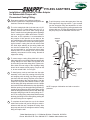
PITLESS ADAPTERS
Conduit
Tapping
Stainless
Control
Cable
Conduit
Well
Casing
Neck
Discharge
Pipe
Casing
Fitting
Actuator
Drop
Pipe
Fitting
Drop
Pipe
6 To pull the pump, remove the upper part of the cap.
First support the drop pipe with a 1" pipe screwed
into the drop pipe tting and attached to a hoist.
Then release the drop pipe by pulling upward on the
release cable eye. The drop pipe assembly including
the pump may now be withdrawn from the well.
Installation Instructions for Pitless Adapter
for Submersible Pumps with
Pressurized Casing Fitting.
1 Excavate around the well casing according to
government regulations to a depth sufciently below the
frostline to mount the casing tting.
2 To cut the casing hole with a hole saw use a 2-1/8"
diameter saw for 4" casing ttings and a 2-1/2" or
(63mm) diameter saw for all other casing ttings
sizes. Locate the hole at right angles to the discharge
line for a swing joint. A Black and Decker "Twiston"
hole saw, or the equivalent, is recommended for
this purpose. A little practice on the basis of the
saw manufacturer's instructions is required for best
results. It is important to remove the inward project-
ing n formed in cutting the hole with a half round
le. Steel chips adhering to the casing inside and
out must be brushed away. The torch cut hole is
not recommended for a pressurized casing tting
because there is not enough room for the errors
ordinarily encountered in torch cutting. Smooth all
edges after drilling.
3 To mount strap to casing tting hold bolt in place,
slide casing tting over the bolt ends and against the
casing and spin on nuts. Make sure that the inner
lip of the tting enters the casing hole. Tighten nuts,
after which the outer edge of the discharge tting
should be in contact with the casing. Torque to 10#
ft., do not exceed 20# ft. for PVC pipe.
4 To install pump, make up and lower the drop pipe
assembly in the usual way, starting with the pump
and stopping with the drop pipe tting supported
just above the well casing. Tape the motor cable to
the unlabeled side of the drop pipe tting. Coat the
neoprene O-ring with clean vaseline. Screw a 1" pipe
into the drop pipe tting and attach to hoist. Untape
and uncoil the cable attached to the drop pipe tting.
With the opening in the drop pipe tting extending in
exactly the same direction as the casing tting, slowly
lower the drop pipe assembly into the well. When the
drop pipe tting aligns with the casing tting the "T"
arm of the casing tting snaps downward thrusting
the drop pipe tting into the casing tting sealing the
joint and locking the two together.
5 To complete the well insert the eye of the release
cable back into the well just far enough to avoid in-
terference with the cap. Complete the wiring. Start
the pump and check for leakage around the casing
tting and cap the well.
NOTE: Improper chlorination can lead to corrosion
problems.
-
 1
1
-
 2
2


Baker Manufacturing 8PL41U Installation guide
- Type
- Installation guide
Ask a question and I''ll find the answer in the document
Finding information in a document is now easier with AI
Other documents
-
Flint & Walling 4F11P05305S Installation guide
-
Craftsman 390284380 Owner's manual
-
Zoeller 1452-0008 Operating instructions
-
Rehau Outdoor Wood Boiler Pipe Installation guide
-
Zoeller 1452-0005 Operating instructions
-
Raychem Mini WinterGard 120 Volt Installation guide
-
Everbilt EBPA100NL Operating instructions
-
Land Rover Discovery Owner's manual
-
Uponor 5017935 Installation guide
-
Wayne CWS75n Operating instructions