Page is loading ...

INSTRUCTION MANUAL
CAUTION: Read All Instructions Before Operating Equipment
MFJ ENTERPRISES, INC.
300 Industrial Park Road
Starkville, MS 39759 USA
Tel: 662-323-5869 Fax: 662-323-6551
COPYRIGHT MMVI MFJ ENTERPRISES, INC.
C
Model MFJ-654
VERSION 1A

DISCLAIMER
Information in this manual is designed for user purposes only and is not
intended to supersede information contained in customer regulations, technical
manuals/documents, positional handbooks, or other official publications. The
copy of this manual provided to the customer will not be updated to reflect
current data.
Customers using this manual should report errors or omissions,
recommendations for improvements, or other comments to MFJ Enterprises, 300
Industrial Park Road, Starkville, MS 39759. Phone: (662) 323-5869; FAX: (662)
323-6551. Business hours: M-F 8-4:30 CST.

MFJ-654 hamProAudio
TM
Microphone Equalizer/Conditioner Instruction & Technical Manual
-2-
TABLE OF CONTENTS
TOPIC PAGE
1. TABLE OF CONTENTS 2
2. LIST OF FIGURES 2
3. INTRODUCTION AND FEATURES 3
4. TYPICAL SPECIFICATIONS 4
5. SYSTEM CONTROLS 5
a. FRONT PANEL JACKS AND CONTROLS 5
b. REAR PANEL JACKS AND CONTROLS 7
6. SYSTEM SETUP 8
a. INTERNAL HEADERS 8
b. INTERNAL JUMPER BLOCK 9
c. CABLES 17
d. POWER 17
e. HEADPHONES 17
f. RADIO AUDIO 17
7. THEORY OF OPERATION 18
8. MFJ-654 EASY-START INSTRUCTIONS 20
9. IN CASE OF DIFFICULTY 23
10.TECHNICAL ASSISTANCE 23
LIST OF FIGURES
Figure 1 Front Panel Jacks and Controls 5
Figure 2 Rear Panel Jacks and Controls 7
Figure 3 Internal Headers 8
Figure 4-10 Internal Jumper Blocks 9-13
Figure 12 Yaesu Mic Jack Pinout, Front View 14
Figure 13 Functional Diagram 18
Figure 14 Compression and Gating Characteristics 19
Figure 15-16 Schematic 24-25
LIST OF TABLES
Table 1 Sample Jumper Settings Table for Yaesu FT-1000 Series 14
Table 2 Microphone Pinout 16

INTRODUCTION & FEATURES
INTRODUCTION
The MFJ-654 hamProAudio Microphone Equalizer/Conditioner was designed
with the serious operator in mind. Based on the Broadcast Industry Standard
Speech Compression IC the SSM-2166 from Analog Devices it allows the
operator flexibility in the use of input sources and output methods.
The 8 band Equalizer was designed to use the most desired center frequencies
and “Q” possible.
FEATURES
Choice of 3 Input Sources: In order to add versatility MFJ has included the
following input sources for the MFJ-654:
1. A standard RJ-45 input jack common to most new radios.
2. Standard 8 pin round chassis connector for the majority of the radios
produced in the last 25 years.
3. MFJ’s own input consisting of a 3.5 -mm jack that allows the user to
choose from feeding audio, audio and a PTT function for use with the Heil
series of Boom-Mic Headsets, or even provides phantom voltage on the
tip for the MFJ-393 Boom-Mic Headphones or on the ring for use with a
computer Boom-Mic or Boom-Mic headset.
These features are included along with allowing you to feed audio from a
computer, TNC or Modem.
Fully Adjustable Gain Amplifier: You have control of the output level to bring
weak microphones up to a useful level or will provide over 1.2 volts peak to peak
using the auxiliary output.
Wide Range Compression Settings: With an adjustable compression setting
from 1:1 to 15:1 you control the amount of compression to get your signal
thought the toughest of band conditions.
Adjustable Downward Expansion Level and Delay: No more feeding the
background noise into your signal. The MFJ-654 allows you to set the level of
Downward Expansion to only pass audio when you are talking and a delay to
minimize the cutting in and out between words.
Selectable 8 Band Equalizer: You have full control of your audio with up to
±16dB of control for 8 center frequencies.

J-654 hamProAudio
TM
Microphone Equalizer/Conditioner Instruction & Technical Manual
-4-
INTRODUCTION & FEATURES
Audio Pass Through from your Radio: No need to switch the headphones
from the MFJ-654 to the radio. At the push of a button you can instantly switch
from normal operation to a test mode that allows you to adjust the settings
without going on the air with the built in monitor amplifier.
By-pass Function: Switch the MFJ-654 in or out and you still have the radios
audio in the headphones useful when you want to Rag Chew and don’t need the
Compression or Downward Expansion of the MFJ-654.
Multiple Outputs: The MFJ-654 has multiple outputs for both receive/test audio
and Microphone audio. No need to have to hunt for an adapter to switch
between 3.5 -mm or 1/4inch stereo phone jacks. Microphone audio is fed out
through the RJ-45 connector through the 3.5 mm Auxiliary Output or through a
separate 3.5 mm jack that gives true balanced output if you need it.
Rugged Construction: Attractive all-metal cabinet, conservative component
selection, space age SMD Circuitry and extensive RF filtering ensure solid
performance for years to come. Fully covered by MFJ’s “No Matter What” one
year limited warranty.
Before attempting to operate your MFJ-654, please read the manual thoroughly.
It contains important detail about setting up your unit to obtain the best
performance.
TYPICAL SPECIFICATIONS
Input source……………………Dynamic or electret microphone low or high Z
Stereo or Monaural radio audio.
Sound card or Modem
Output ………………………….High or low Z. Adjustable signal level
Bandwidth …………………….20 kHz
Total harmonic distortion ….1% maximum, <0.2% typical.

J-654 hamProAudio
TM
Microphone Equalizer/Conditioner Instruction & Technical Manual
-5-
SYSTEM CONTROLS
MFJ-654 JACKS AND CONTROLS
COMPRESSION MONITORLEVEL DELAYOUTPUT
BYPASS POWER
INPUT
DOWNWARD EXPANSION
Max Min Max Min
OFF
ON
OUTPUT LEVEL POWER
MICROPHONE IN
EQ INPUT LEVEL
Max Min Max Min Max Min
400 Hz200 Hz100 Hz50 Hz
+
-
3200 Hz2400 Hz1600 Hz800 Hz
+
-
+
-
+
-
+
-
+
-
+
-
+
-
ON
OFF
ON
OFF/BYPASS
MFJ Microphone Equalizer/ConditionerhamProAudio™
MFJ-654
EQUALIZER
0 0 0 0 0 0 0 0
Max
Min
Figure 1: MFJ-654 Front Panel Jacks and Controls
Bottom Rows
1. 8 pin Microphone Input Jack: Accepts input from any standard 8 pin
microphone.
2. RJ-45 Microphone Input Jack: Accepts the input from a standard RJ-45
Microphone.
3. Compression Level: Controls the Compression function from no
Compression to 15:1 maximum Compression.
4. Equalizer Input Level LED: This LED allows you to set the input level to
the Equalizer section.
5. Input Level Gain: This control sets the input level to the Equalizer
section.
6. Output Gain Level LED: A one time adjustment will allow this LED to
monitor your output level and allow you to set the gain level for any input
source easily.
7. Output Level Gain: Allows a wide range of output levels for various
radios or other uses.
8. Downward Expansion Level: Allows adjustment of the required audio
level to allow the unit to pass audio. Great for noisy conditions.
1 2 3 4 5 6 7 98 10 11 12
13
14 15 16 17 18 19 20 21 22

J-654 hamProAudio
TM
Microphone Equalizer/Conditioner Instruction & Technical Manual
-6-
SYSTEM CONTROLS
9. Downward Expansion Delay: Sets the amount of time that the internal
amplifier will remain open with no audio. Great to hold the audio open
between syllables and words.
10. Power On LED: Instant visual identification if you are using the MFJ-654
or just the standard microphone.
11. Monitor Gain: Control the audio level in the headphones when in the test
position.
12. Bypass ON/OFF Switch: Allows you to either use your Microphone direct
(out) or through the MFJ-655 (in).
13. Power ON/OFF Switch: Cuts the power to the unit on (in) or off (out).
Top Rows
14. 50 Hz: Cuts or emphasizes lowest speech frequencies.
15. 100 Hz: Cuts or emphasizes lowest speech frequencies.
16. 200 Hz: Cuts or emphasizes lowest speech frequencies.
17. 400 Hz: Cuts or emphasizes mid-range speech frequencies.
18. 800 Hz: Cuts or emphasizes mid-range speech frequencies.
19. 1600 Hz: Cuts or emphasizes upper-range speech frequencies.
20. 2400 Hz: Cuts or emphasizes syllabant sounds and adjacent channel
“chatter”.
21. 3200 Hz: Cuts or emphasizes syllabant sounds and adjacent channel
“chatter”.
22. Equalizer ON & OFF/Bypass: Cuts the Equalizer on (in) or off (out).

J-654 hamProAudio
TM
Microphone Equalizer/Conditioner Instruction & Technical Manual
-7-
SYSTEM CONTROLS
OUTPUT
LEVEL
LED
MICROPHONE
OUT
MFJ ENTERPRISES, INC.
STARKVILLE, MS USA
POWER
12VDC
FROM MFJ-654
FROM RADIO
EXTERNAL
PTT
SWITCH
AUX.
AUDIO
OUTPUT
BALANCED
AUDIO
OUTPUT
AUX.
AUDIO
INPUT
RECEIVED
AUDIO
INPUT
OUT
HEADPHONE AUDIO
Figure 2: MFJ-654 Rear Panel Jacks and Controls
1. Power: Accepts 2.1 –mm power plug to supply 12-15 Vdc to the unit.
2. From Radio/From MFJ-654: This switch allows the audio to be fed from
the radio to the headphones or in the test mode for the audio from the
microphone to be fed to the headphones for setting the MFJ-654.
Additionally in the test mode the PTT is disabled allowing you to key the
microphone without keying the radio.
3. Headphone Output: Allows you to use a pair of 3.5 –mm stereo
headphones. The test audio is mono fed into both sides of the phones.
The radio audio is what your radio puts out. Handy if you have a Main and
a Sub-receiver.
4. Headphone Ouput: Same function as number 3 but for ¼ inch stereo
headphones.
5. External PTT Input: This ¼ inch jack allows PTT from a Hand Switch or
Foot Switch.
6. Auxiliary Output: This 3.5 –mm jack allows direct audio to be fed out
from the unit. Useful when high levels of audio are required as up to 1.2
volts peak to peak are available.
7. Balanced Output: This 3.5 –mm stereo jack give a balanced output.
8. Output LED Level Set: This trim pot is used to adjust the point at which
the LED illuminates.
9. Auxiliary Input: This multifunction input allows just about anything to be
used with the MFJ-654 by setting the appropriate input jumpers.
10. RJ-45 Output: This is where the MFJ-5398 or the MFJ-5397MX is
attached.
11. Received Audio Input: This jack allows either stereo or mono (if wired
properly) audio from your radio is applied.
1 2 3 4 5 6 7 9 8 10 11

J-654 hamProAudio
TM
Microphone Equalizer/Conditioner Instruction & Technical Manual
-8-
SYSTEM SETUP
INTERNAL HEADERS
Figure 3: Internal Headers
1. Header 1: This sets the input of the unit to your specific microphone. Default 1-2 is set
to 680 ohms the standard impedance setting for most stock microphones. If you need
low impedance then move the jumper to positions 3-4. Remove for high impedance
microphones.
2. Header 3: This allows the PTT line to be placed on the ring of the 3.5 –mm auxiliary
input jack. Default is off.
3. Header 4: This header allows phantom voltage to be fed to electret microphones
Default is 0 volts pins 1-2 shorted. Move this jumper to pins 3-4 for 1.5 volts, 5-6 for 5
volts or 7-8 for 8 volts.
4. Header 5: High impedance output. Default is shorted for low impedance output but if
required remove this jumper for approximately 50K output impedance.
5. Header 6: This header allows the phantom voltage set by header 4 to be passed to the
ring of the Auxiliary input jack. Default is off. If used with standard computer
microphone/headphones set to 5 volts.
6. Header 7: This header ties the CT of the output transformer allowing a balance output
to be available at the 3.5 –mm jack. Default is off.
7. Header 8: This header allows the PTT line to be placed on the Auxiliary Output ring
terminal of the 3.5 –mm jack. Default is off.
8. Header 9: This Header places phantom voltage on the microphone input line and the tip
of the 3.5 mm input jack. It must be shorted when using a microphone requiring phantom
voltage.
9. Header 10: This header allows the transformer to be bypassed to increase the low
frequency response. Default is 1-2 not bypassed.
10. Header 11: This header allows the transformer to be bypassed to increase the low
frequency response. Default is 1-2 not bypassed.
11. Header 12: This header grounds the Mic Ground to the radio and must be shorted if the
transformer is being bypassed. Default is off.

J-654 hamProAudio
TM
Microphone Equalizer/Conditioner Instruction & Technical Manual
-9-
SYSTEM SETUP
Figure 4: Internal Jumper Blocks
Refer to Table 1 for common microphones. Consult your owner’s manual to
determine your specific microphone pinout.
1. Jumper 2: PTT from the Microphone. Place a jumper on the pin number that
corresponds to the pin of your microphone that supplies the PTT line to the radio.
2. Jumper 3: Microphone Audio Ground. Place a jumper on the pin number
that corresponds to the pin that supplies the shielded ground from the
microphone.
3. Jumper 4: Microphone Audio Input. Place a jumper on the pin number that
corresponds to the pin that supplies microphone audio.
4. Jumper 5: Pass/Thru. This allows you to pas any other lines from the
microphone for feature such as up/down/fast. Normally all lines that are not
being used for the Mic Audio, Mic Ground and PTT line will be jumpered.
5. Jumper 7: PTT to Radio. Place a jumper on the pin corresponding to the pin
that your radio requires for PTT
6. Jumper 8: Microphone Audio Ground to Radio. Place a jumper on the pin
that corresponds to the pin that your radio requires for the shielded ground.
7. Jumper 9: Microphone Audio to Radio. Place a jumper on the pin that
corresponds to the pin on your radio that feeds microphone audio to the radio.

J-654 hamProAudio
TM
Microphone Equalizer/Conditioner Instruction & Technical Manual
-10-
SYSTEM SETUP
Front panel view of Mic Jacks.
Refer to this drawing for the numbering of the headers from 1 to 8. The RJ-45 is numbered with
the clip down. Note the position of the key for the 8 pin round mic jack. This could be rotated on
your particular unit.
INTERNAL JUMPER BLOCKS
The Jumper Installation diagrams within this instruction manual will help you in
setting up your MFJ-654 to match your radio. If your radio is not listed with the
diagram, it means that we have not verified your radio to use that diagram. You
can try to install jumpers as indicated. If that does not work, please refer to the
radio manual to identify the MIC pin assignment for you radio then follow the
instructions given at the end of this section in the MFJ-654 instruction manual to
install the jumpers.
ICOM 8-Pin Round Microphone Setup:
IC-255, 288, 28, 290, 38A, 375, 707, 718, 725, 726, 728, 729, 730, 735, 737, 745, 746, 746PRO,
751, IC-756, 756PRO, 756PROII, 775DSP, 761, 78, 781, 910H
This diagram may cover some
other radios in the ICOM product
line with 8-pin round microphone
jack.
If there are any Questions
concerning the information
provided, please refer to your
RADIO INSTRUCTION
MANUAL.
MFJ is neither liable nor
responsible for any mistakes or
errors in the information
provided.
Receive Audio is taken from the
Headphone Audio Output.
Figure 5: ICOM 8-Pin Round Microphone Setup

J-654 hamProAudio
TM
Microphone Equalizer/Conditioner Instruction & Technical Manual
-11-
SYSTEM SETUP
ICOM 8-Pin Modular Microphone Setup:
IC-207H, 2720H, 2800H, 703, 706, 706MKII, 706MKIIG, V8000
This diagram may cover some
other radios in the ICOM
product line with 8-pin modular
microphone jack.
If there are any Questions
concerning the information
provided, please refer to your
RADIO INSTRUCTION
MANUAL.
MFJ is neither liable nor
responsible for any mistakes or
errors in the information
provided.
Receive Audio is taken from
the Headphone Audio Output.
Figure 6: ICOM 8-Pin Modular Microphone Setup
Figure 7: YAESU 8-Pin Round Microphone Setup
YAESU 8-Pin Round Microphone Setup:
YAESU FT-650, 707, 712, 726, 736, 756, 767, 77, 790II, 700, 840, 890, 990, 1000D
This diagram may cover some
other radios in the YAESU
product line with 8-pin round
microphone jack.
If there are any Questions
concerning the information
provided, please refer to your
RADIO INSTRUCTION
MANUAL.
MFJ is neither liable nor
responsible for any mistakes or
errors in the information
provided.
Receive Audio is taken from the
Headphone Audio Output.

J-654 hamProAudio
TM
Microphone Equalizer/Conditioner Instruction & Technical Manual
-12-
SYSTEM SETUP
YAESU 8-Pin Modular Microphone Setup:
YAESU FT-817, 857, 897
This diagram may cover some
other radios in the YAESU
product line with 8-pin modular
microphone jack.
If there are any Questions
concerning the information
provided, please refer to your
RADIO INSTRUCTION
MANUAL.
MFJ is neither liable nor
responsible for any mistakes or
errors in the information
provided.
Receive Audio is taken from
the Headphone Audio Output.
Figure 8: YAESU 8-Pin Modular Microphone Setup
Figure 9: KENWOOD 8-Pin Round Microphone Setup
KENWOOD 8-Pin Round Microphone Setup:
TS-50, 60, 140, 430, 440, 450, 570, 660, 670, 680, 690, 711, 780, 811, 850, 870, 930, 940, 950
TM-201A, 201B, 211, 221, 231, 241, 321, 331, 401A, 401B, 421, 431, 441, 521, 531, 541, 621
TM-631, 701, 721, 731, 2530, 2550, 2570, TR-50, 751, 851, TW-4000, 4100
This diagram may cover some
other radios in the Kenwood
product line with 8-pin round
microphone jack.
If there are any Questions
concerning the information
provided, please refer to your
RADIO INSTRUCTION
MANUAL.
MFJ is neither liable nor
responsible for any mistakes or
errors in the information
provided.
Receive Audio is taken from the
Headphone Audio Output .

J-654 hamProAudio
TM
Microphone Equalizer/Conditioner Instruction & Technical Manual
-13-
SYSTEM SETUP
KENWOOD 8-Pin Modular Microphone Setup:
TM-251, 255, 261, 451, 461, 641, 642, 732, 733, 741, 742, 941, 942, G707, V7A
This diagram may cover some
other radios in the Kenwood
product line with 8-pin modular
microphone jack.
If there are any Questions
concerning the information
provided, please refer to your
RADIO INSTRUCTION
MANUAL.
MFJ is neither liable nor
responsible for any mistakes or
errors in the information
provided.
Receive Audio is taken from
the Headphone Audio Output .
Figure 10: KENWOOD 8-Pin Modular Microphone Setup

J-654 hamProAudio
TM
Microphone Equalizer/Conditioner Instruction & Technical Manual
-14-
SYSTEM SETUP
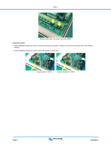
CUSTOMIZING INTERNAL JUMPERS
If your radio is not listed above, you can create a custom jumper position table.
Begin by removing the screws from the sides of the cabinet. Lift the cover off.
Look from the front view and notice the group of pins and black jumpers on the
left side behind the microphone connector and in front of the microphone output
jack. Fill in a custom table like the following:
Pin JP8 rad
mic gnd
Jp3 mic
gnd
JP5
pass
JP4 mic
audio
JP7 rad
ptt
JP2 mic
ptt
JP9 rad
audio
1 X
2 X
2 X
4 X
5 X
6 X X
7 X X X
8 X X
Table 1: Sample Jumper Settings Table for Yaesu FT-1000 Series
UNLISTED RADIOS
To make a jumper table for an unlisted radio, you must look at the radio manual.
Find the page that shows the microphone wiring. This is a sample of a Yaesu-
style wiring diagram that was used above:
Figure 12:
PTT
Mic
Mic Gnd
Yaesu Mic Jack Pin-out, Front View
8
7
6
5
PTT Gnd
If you compare table 1 to this connector diagram, you will see how it is laid out.
Notice an “X” was placed at the appropriate PTT and MIC pins according to the
rules below.
Look at the microphone-wiring diagram in your radio manual, fill in a table, and
connect the leads as we have done in our example. We have provided a blank
chart below for you to fill in.

J-654 hamProAudio
TM
Microphone Equalizer/Conditioner Instruction & Technical Manual
-15-
SYSTEM SETUP
1.) Jumper 4 and 9 should copy each other, and use the same jumper
pin number for the center MIC wire.
2.) Jumper 2 and 7 also jointly share the same pin numbers as the PTT
pin.
3.) The MIC GND, Jumper, should connect to the same pin as the outer
MIC lead and only that pin.
4.) Be sure to place a pass-through connection jumper on every lead
EXCEPT numbers used on HD 2, 4, 7, and 9.
The following blank table is for your personal use. Use your radio’s manual to
complete the table. This will assist you in properly setting the jumpers for your
radio.
Remember!!! Use the following wiring chart rules:
1.) Never ground the microphone audio ground to the chassis ground!
2.) JP4 and JP9 are always the same jumper slot number
3.) JP2 and JP6 are always the same jumper slot number
4.) JP5 always has a jumper except where JP2, JP4, JP7 and JP9 are
jumpered!
Pin JP8 rad
mic gnd
JP3 mic
gnd
JP5
pass
JP4 mic
audio
JP7 rad
ptt
JP2 mic
ptt
JP9 rad
audio
1
2
3
4
5
6
7
8

J-654 hamProAudio
TM
Microphone Equalizer/Conditioner Instruction & Technical Manual
-16-
SYSTEM SETUP
Radio Pin 1 Pin 2 Pin 3 Pin 4 Pin 5 Pin 6 Pin 7 Pin 8
Alinco
MIC
AUDIO
PTT DOWN UP 5
VOLTS
AF
OUT
MIC
GND
GND
Icom
MIC
AUDIO
+8
VOLTS
UP/DOWN SQL PTT PTT
GND
MIC
GND
Kenwood
MIC
AUDIO
PTT DOWN UP 8
VOLTS
NC MIC
GND
PTT
GND
Yaesu FT1000
FT847
UP GND DOWN FAST GND PTT MIC
GND
MIC
AUDIO
Yaesu FT-990
FT-1000MP
UP +5
VOLTS
DOWN FAST GND PTT MIC
GND
MIC
AUDIO
Table 2: Common Microphone Pinouts

J-654 hamProAudio
TM
Microphone Equalizer/Conditioner Instruction & Technical Manual
-17-
SYSTEM SETUP
CABLES
Simply connect your microphone to the appropriate input and use either a MFJ-
5398 for 8 pin Round or MFJ-5397MX for 8 pin Modular connector to the output
on the rear of the unit and attach to your radio.
Connect the audio from your headphone jack to the 3.5-mm jack on the MFJ-
654. If your radio output is mono then simply wire the tip and the ring of the
cable to provide audio to both sides of the headphones.
Connect a Foot Switch or Hand Switch to the PTT jack located on the rear of the
unit.
POWER
The MFJ-654 will operate with any well-filtered 10-14 VDC power supply capable
of at least 150 mA. The required power connector is a 2.1 -mm ID, 5.5 mm OD
coaxial power plug.
As this is a quality audio unit, use of an unregulated wall power supply
transformer is not recommended as the unloaded voltages can easily exceed 15
volts and the lack of filtration and regulation can introduce hum and other
components into your signal.
Wire (+) voltage to center and (-) to common.
HEADPHONES
Use stereo headphones rated at 8-40 Ohms impedance. Jacks for either ¼ inch
or 3.5 –mm headphones are included on the rear of the unit. Use of quality
phones will aid in the reproduction of the audio when setting up the unit.
RADIO AUDIO
If your radio provides left and right output for a main and a sub-receiver then use
a stereo 3.5 –mm to the termination that your radio uses.
If your radio provides mono output then either use a stereo 3.5 –mm cable and
connect the tip and ring and then attach the termination that your radio uses.

J-654 hamProAudio
TM
Microphone Equalizer/Conditioner Instruction & Technical Manual
-18-
THEORY OF OPERATION
The SSM2166 is a complete microphone signal condition system on a single IC.
It provides amplification, RMS detection, limiting, variable Compression and
Downward Expansion.
Figure 13: Functional Diagram
Figure 13 shows the functional diagram of the SSM2166. Input signals below
Vde set by The Downward Expansion control on the front panel are downward
expanded, that is a -1dB change in the input signal level causes a -3dB change
in the output level. The average time for this feature is set by the Delay control
on the front panel. Overall gain of the MFJ-654 is set by controlling the Vca
through the front panel control. Gains of up to 20 dB are available. Compression
is set by the front panel control and ratios of 1:1 up to 15:1 are possible.

J-654 hamProAudio
TM
Microphone Equalizer/Conditioner Instruction & Technical Manual
-19-
THEORY OF OPERATION
Figure 14: Compression and Gating Characteristics
Figure 14 shows how the input levels are compressed for various levels of
compression within the SSM2166. Compression is a method of signal
processing that the loudest signals are made softer and the quietest signal are
boosted this reduces the overall dynamics of the signal but this also makes the
output appear louder to the ear.
Bypassing the Output Transformer: All transformers will roll off the lower
frequencies particularly below 200HZ while this is desirable for DX situations
some users may find this undesirable. If this is the case and the added isolation
of the transformer is not required then simply set the jumpers 10-12 to the
required location to bypass the audio transformer.
/