7
Symptom Possible Cause Corrective Action
No Heat/
No Cool/
No Fan
(common problem)
1.) Blown fuse or tripped circuit
breaker
2.) Furnace power switch to OFF
3.) Furnace blower compartment
door panel loose or not
properly installed
4.) Loose connection to
thermostat or system
1.) Replace fuse or reset breaker
2.) Turn switch to ON
3.) Replace door panel in proper position to engage
safety interlock or door switch
4.) Tighten Connections
No Heat
1.) System Switch not set to
Heat
2.) Loose connection to
thermostat or system
3.) Heating System requires
service or thermostat
requires replacement
Verify thermostat and system wires are securely
aached.
Diagnosc: Set System Switch to Heat and raise
the setpoint above room temperature. Within ve
minutes the thermostat should make a so click
sound and “Heat On” should appear on display.
This sound indicates the thermostat is operang
properly. If the thermostat does not click, try the
reset operaon listed below. If the thermostat does
not click aer being reset, contact your heang and
cooling service person or place of purchase for a
replacement. If the thermostat clicks, contact the
furnace manufacturer or a service person to verify
the heang system is operang correctly.
No Cool
1.) System Switch not set to
Cool
2.) Loose connection to
thermostat or system
3.) Cooling System requires
service or thermostat
requires replacement
Verify thermostat and system wires are securely
aached.
Diagnosc: Set System Switch to Cool and lower
setpoint below room temperature. Same procedures
as diagnosc for “No Heat” condion except set the
thermostat to Cool and lower the setpoint below the
room temperature. There may be up to a ve minute
delay before the thermostat clicks in Cooling if the
compressor lock-out opon is selected in the installer
menu. (see INSTALLER MENU, item 50)
Heat, Cool or Fan
Runs Constantly
Possible short in wiring,
thermostat, heat, cool or fan
system
Check each wire connection to verify they are not
shorted or touching other wires. Try resetting the
thermostat. If the condition persists contact your
HVAC service person.
Thermostat Display
& Thermometer
Disagree
Thermostat display requires
adjustment
Display can be adjusted +/-5°. See User Menu item
04
TROUBLESHOOTING
(Troubleshooting continued on next page)
Resetting the Thermostat or Thermostat Settings
If the thermostat has good batteries, but has a blank display or does not respond to key
presses, the thermostat should be reset by removing the batteries for 2 minutes. This reset
will not change the menu settings. If the condition persists after reinstalling the batteries,
replace the thermostat.
To conveniently reset only the user settings back to factory defaults, press Menu and Back-
light buttons at the same time and hold until the display goes blank and resets.
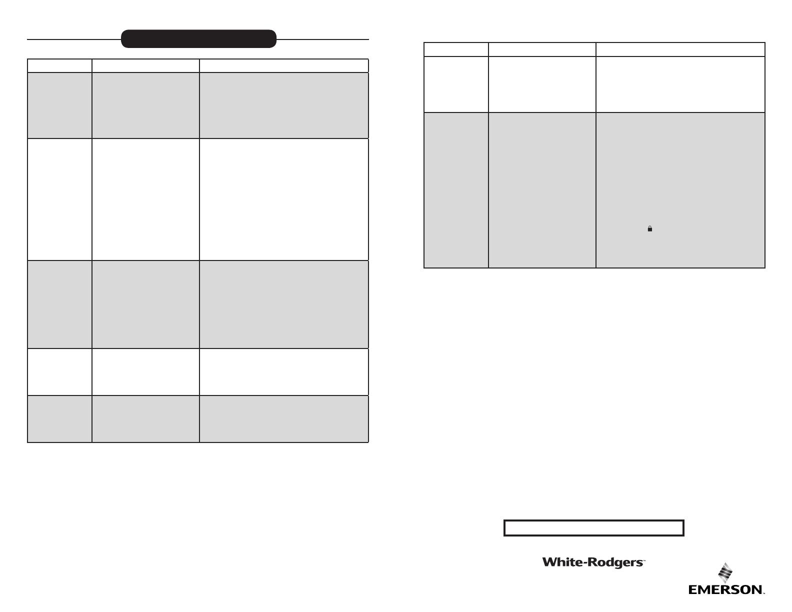
Symptom Possible Cause Corrective Action
Furnace (Air
Conditioner)
Cycles Too Fast or
Slow (narrow or
wide temperature
swing)
The location of the thermostat
and/or the size of the Heating
System may be inuencing the
cycle rate
Digital thermostats provide precise control and cycle
faster than older mechanical models. The system
turns on and o more frequently but runs for a shorter
time. If you would like to increase cycle time, choose
SLO for slow cycle in the Installer menu. (Reference
menu items 30 & 35) If an acceptable cycle rate is not
achieved, contact your HVAC service person.
“Call for Service”
icon appears on
displayed
1.) Heating system is not able
to heat the space to within
10 degrees of the setpoint
within 2 hours
2.) Cooling system is not able
to cool the space to within
10 degrees of the setpoint
within 2 hours
3.) If “--” is displayed for the
Room Temperature, a
replacement thermostat is
needed
4.) None of the buttons operate
on the thermostat
1.) See corrective action for “No Heat”
2.) See corrective action for “No Cool”
3.) Replace thermostat
4.) Make sure keypad lockout is not turned on
(denoted by icon)
TROUBLESHOOTING (C0ntinued)
HOMEOWNER HELP LINE: 1-800-284-2925
White-Rodgers is a business
of Emerson Electric Co.
The Emerson logo is a
trademark and service mark
of Emerson Electric Co.
www.white-rodgers.com
www.emersonclimate.com


