Maytag MDE6400AYQ Installation guide

Category
Electric laundry dryers
Type
Installation guide
AUTOMATIC DRYER
INSTALLATION INSTRUCTIONS
The installation, including a proper exhaust system,
is the responsibility of the owner.
LEAVE THESE INSTRUCTIONS WITH THE OWNER
Printed in U.S.A. 6 3716990
Read this before you start...
Tools needed for installation
Teflon tape or pipe
joint compound (gas only)
Cutting knife
Pipe wrench (gas only)
Nut drivers
Level
Screw driver (standard)
Duct tape
Crescent wrench
ITEMS PROVIDED
®®o gQ
® %d\@ @
Electric Dryer Gas Dryer
Only Only
Proper installation is the responsibility of the owner.
HOWEVER, SERVICE CALLS PERFORMED AS A RESULT OF POOR SET-UP, ADJUSTMENT AND
CONNECTION ARE THE RESPONSIBILITY OF THE INSTALLER.
Make sure you have everything necessary for proper installation.
1. GROUNDED ELECTRICAL OUTLET is required. See Electric Requirements.
2. POWER CORD for electric dryers (except Canada).
3. GAS LINES (if a gas dryer) must meet National and Local Codes.
4. EXHAUST SYSTEM - must be rigid metal or flexible stiff walled metal exhaust ducting. See Exhaust Requirements.
43 1/4"
minimum
36.1/4"
_Imlnlmum
1 1/2"
IMPORTANT TO INSTALLER
PLEASE READ THE FOLLOWING INSTRUCTIONS
CAREFULLY BEFORE STARTING TO INSTALL
THE DRYER. THESE INSTRUCTIONS SHOULD
BE RETAINED FOR FUTURE REFERENCE.
REMOVE THE DOOR FROM ALL DISCARDED
APPLIANCES SUCH AS DRYERS TO AVOID THE
DANGER OF A CHILD SUFFOCATING.
LOCATION CONSIDERATIONS
The dryer should be located to permit adequate
room in front for loading the dryer, and sufficient
room behind the dryer for the exhaust system.
This dryer is factory-ready for rear exhaust. To
exhaust out the bottom or left side, use the acces-
sory exhaust kit (see Accessories). Instructions are
included with the kit.
It is important to make sure the room has adequate
make-up air. The area where the dryer is located must
not obstruct the flow of combustion or ventilating air.
On gas dryers, adequate clearance as noted on the
data plate must be maintained to insure adequate
air for combustion and proper operation of the dryer.
THE DRYER MUST NOT BE INSTALLED OR
STORED IN AN AREA WHERE IT WILL BE
EXPOSED TO WATER AND/OR WEATHER. THE
DRYER AREA IS TO BE KEPT CLEAR AND FREE
FROM COMBUSTIBLE MATERIALS, GASOLINE
AND OTHER FLAMMABLE VAPORS AND
LIQUIDS. A DRYER PRODUCES COMBUSTIBLE
LINT. THE AREAAROUND THE DRYER SHOULD
BE KEPT FREE OF LINT.
ALCOVE OR CLOSET
INSTALLATION
An appliance instal-
led in a closet shall
have no other fuel-
burning appliance
installed in the
same closet.
Each opening area
in the door must
_I,WARNING WARNING-
The dryer must
be exhausted to
the outside to
reduce the risk
of fire when
installed in an alcove or closet•
eq i
0"
have a minimum of 36 square inches. These open-
ings must not be obstructed. (Louvered door with
uivalent air opening is acceptable.)
CLOSET DOOR
[7,, 2
FRONT VIEW
Minimum installation clearances. If possible, more
clearance is recommended.
MOBILE HOME INSTALLATION
The installation of the dryer in mobile homes must
conform to the Manufactured Home Construction and
Safety Standard Title 24 CFR, Part 32-80 {formerly
the Federal standard for Mobile Home Construction
and Safety, Title 24, HUD (Part 280), 1975} for the
United States,) or CSA Standards Z240 (for Canada).
When installing a dryer in a mobile home, provisions
for anchoring the dryer to the floor must be made.
An anchor bracket kit is available with instructions
(see Accessories). Locate in an area that has
adequate make up air. A minimum of 25 square
inches of unobstructed opening is required.
All mobile home installations must be exhausted to
the outside with the exhaust duct termination
securely fastened to the mobile home structure,
using materials that will not support combustion.
The exhaust duct may not terminate beneath the
mobile home. See the section on exhausting for
more information.
EXHAUSTING
Exhausting the dryer to the outside will prevent
large amounts of lint and moisture from being blown
into the room.
In the United States:
all gas dryers must be exhausted to the outside.
electric dryers located in a confined area
such as a bedroom, bathroom, or closet
must be exhausted to the outside.
electric dryers not located in a confined area
may be exhausted to the inside (see nonex-
hausted installations).
In Canada:
all gas and electric dryers must be exhaust-
ed to the outside.
Outside the U.S. and Canada:
refer to local codes.
_,WARNING WARNING- plastic or nonmetal
flexible duct presents a potential
fire hazard•
NEVER USE PLASTIC OR NON-
METAL FLEXIBLE DUCT.
If your existing ductwork is plastic, nonmetal or
combustible, replace it with metal. Use only metal
exhaust duct that will not support combustion to
insure the containment of exhaust air, heat and lint.
Plastic flexible duct can kink, sag, be punctured, reduce
air flow, extend drying times and affect dryer operation.
USE A MINIMUM OF 4-INCH DIAMETER RIGID
ALUMINUM OR RIGID GALVANIZED STEEL
DUCT. Do not use smaller duct. Ducts larger than
4 inches in diameter can result in increased lint
accumulation. Lint accumulation should be cleaned
regularly. If flexible metal duct must be used, use
the type with a stiff sheet metal wall. Do not use
flexible duct with a thin foil wall. Serious blockage
can result if flexible metal duct is bent too sharp.
Never install any type of flexible duct in walls, ceil-
ings or other concealed spaces.
Number
of
90°Turns
0
1
2
3
4
Exhaust Hood Type
Maximum length of 4-inch diameter
rigid metal duct
65 ft.
54 ft.
44 ft.
36 ft.
28 ft.
Maximum length of 4-inch diameter
flexible stiff walled metal duct
59 ft.
48 ft.
38 ft.
30 ft.
22 ft.
0
1
2
3
4
36 ft.
32 ft.
28 ft.
25 ft.
23 ft.
28 ft.
24 ft.
20 ft.
17ft.
15ft.
Keep exhaust duct as straight and short as possible.
Exhaust systems longer than recommended can
extend drying times, affect machine operation and
may collect lint. Secure joints with duct tape. Do
not use screws.
DO NOT EXHAUST DRYER INTO ANY WALL,
CEILING, CRAWL SPACE OR A CONCEALED
SPACE OF A BUILDING, GAS VENT, ANY
OTHER COMMON DUCT OR CHIMNEY. THIS
COULD CREATE A FIRE HAZARD FROM LINT
EXPELLED BY THE DRYER.
The exhaust duct should end with an exhaust hood
with a swing out damper to prevent backdrafts and
entry of wildlife. Never use an exhaust hood with a
magnetic damper. The hood should have at least
12 inches of clearance between the bottom of the
hood and the ground or other obstruction. The
hood opening should point down. Never install a
screen over the exhaust outlet.
When possible, do not exhaust the dryer directly
into a window well in order to avoid lint build-up.
Do not exhaust under a house or porch.
If exhaust ductwork must run through an unheated
area, the duct should be insulated and slope slightly
down towards the exhaust hood to reduce conden-
sation and lint build-up.
If an existing exhaust system is to be used with
your new dryer, you must be sure:
The exhaust system meets all local, state and
national codes.
That plastic flexible duct is not used.
To completely inspect and clean all lint accumu-
lation from the interior of the duct.
The duct is not kinked or crushed.
The exhaust hood damper opens and closes freely.
The static pressure in any exhaust system must not
exceed 0.92 inches of water column, or be less
than 0. This can be measured with the dryer
running with a manometer at the point where the
exhaust duct connects to the dryer. A no heat
setting should be used. The dryer tumbler should
be empty and the lint filter clean.
Inspect and clean the interior or the exhaust system
at least once a year. Disconnect electrical service
prior to cleaning. Check the gas line on gas dryers
anytime the dryer is moved.
Frequently check to be sure the exhaust hood
damper opens and closes freely.
NONEXHAUSTED INSTALLATIONS
If the electric dryer is not exhausted to the outside,
the exhaust must not terminate directly behind the
dryer. Use a rectangular vent kit along with a
dacron mesh lint bag (see Accessories). Maintain a
6" clearance between the back of the control panel
and the wall. Although the lint screen and lint bag
will retain most of the lint, a certain amount will be
expelled into the laundry area.
WARNING: IF THE DRYER IS NOT EXHAUSTED
TO THE OUTSIDE, SOME FINE LINT WILL BE
EXPELLED INTO THE LAUNDRY AREA. AN
ACCUMULATION OF DUST OR LINT IN ANY
AREA OF THE HOME CREATES A FIRE
HAZARD. ANY LINT ACCUMULATIONS MUST
BE CLEANED FREQUENTLY.
GAS REQUIREMENTS
Use only Natural or LP (liquid propane) gases.
THE INSTALLATION MUST CONFORM WITH
LOCAL CODES, OR IN THE ABSENCE OF
LOCAL CODES, WITH THE NATIONAL FUEL
GAS CODE ANSI/Z223.1, LATEST REVISION
(FOR THE UNITED STATES), OR WITH THE
CAN/CGA-B149 INSTALLATION CODES (FOR
CANADA).
Gas dryers are equipped with a burner orifice for
operation on NATURAL gas. If the dryer is to be
operated on LP (liquid propane) gas, it must be
converted for safe and proper performance and
must be converted by a qualified service techni-
cian. Conversion kits from NATURAL to LP, or LP
to NATURAL are available through your local
Maytag dealer (see Accessories). If other conver-
sions are required, check with the local gas utility
for specific information concerning conversion
requirements.
A 1/2" gas supply line is recommended and must be
reduced to connect to the 3/8" gas line on the dryer.
The National Fuel Gas Code requires that an
accessible, approved manual gas shut off valve be
installed within 6 feet of the dryer.
Additionally, a 1/8" N.RT. (National Pipe Thread)
plugged tapping, accessible for test gauge
connection, must be installed immediately upstream
of the gas supply connection to the dryer.
The dryer must be disconnected from the gas supply
piping system during any pressure testing of the system.
DO NOT re-use old flexible metal gas line. Flexible
gas line must be design certified by American Gas
Association (CGA in Canada). NOTE: Any pipe
joint compound used must be resistant to the action
of any liquefied petroleum gas.
NOTE: As a courtesy, most local gas utilities will
inspect a gas appliance installation.
GAS IGNITION -
This dryer uses an automatic ignition system to ignite
the burner. There is no constant burning pilot.
ELECTRICAL REQUIREM ENTS
NOTE: Wiring diagram is located inside the control
console.
Export models (not U.S. or Canada): See
Additional Instructions for Export Models on the
other side of this sheet.
_-WARNING WARNING - To prevent unneces-
sary risk of fire, electrical shock or
personal injury, all wiring and
grounding must be done in
accordance with local codes, or
in the absence of local codes,
with the National Electrical Code,
ANSI/NFPA (for the United States) or the
Canadian Electrical Code CSA C22.1 (for
Canada).
GROUNDING
This dryer must be grounded. In the event of
malfunction or breakdown, the ground will reduce
the risk of electrical shock by providing a path of
least resistance for electrical current.
GAS MODELS
This appliance is equipped with a cord having an
equipment-grounding conductor and a grounding
plug. The plug must be plugged into an appropriate
outlet that is properly installed and grounded in
accordance with all local codes and ordinances.
-_WARNING WARNING - Improper connection of
the equipment grounding conductor can
result in a risk of electric shock. Check
with a qualified electrician or serviceman
if you are in doubt as to whether the
appliance is properly grounded.
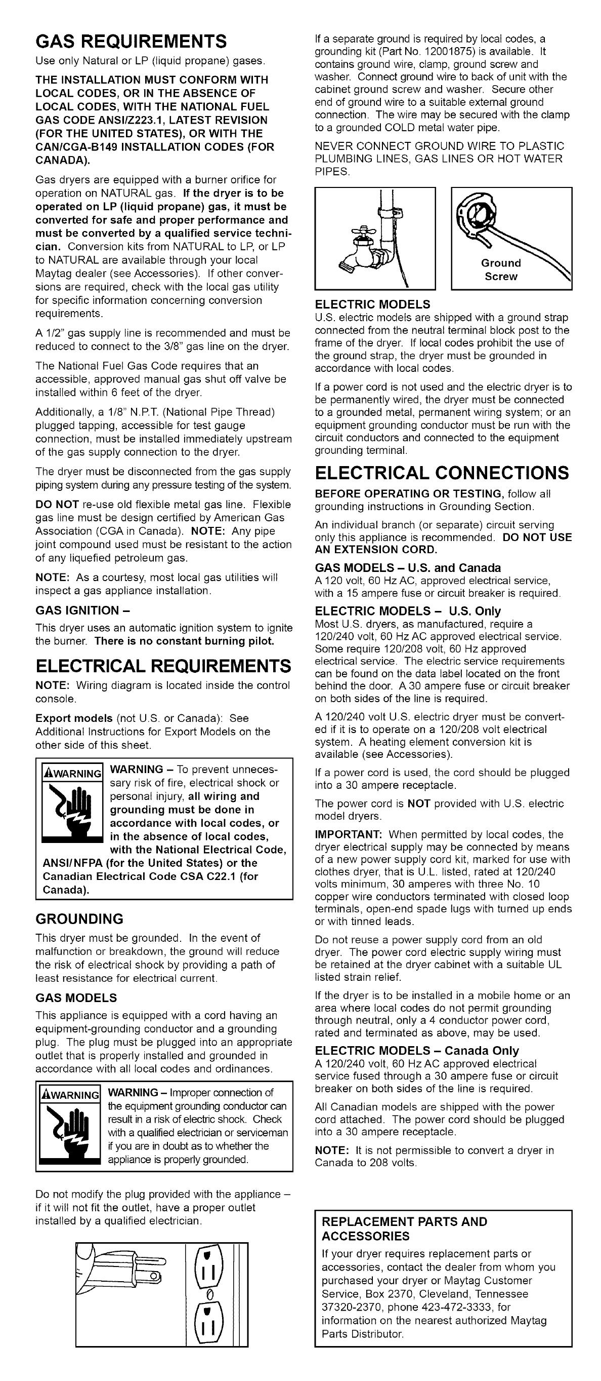
If a separate ground is required by local codes, a
grounding kit (Part No. 12001875) is available. It
contains ground wire, clamp, ground screw and
washer. Connect ground wire to back of unit with the
cabinet ground screw and washer. Secure other
end of ground wire to a suitable external ground
connection. The wire may be secured with the clamp
to a grounded COLD metal water pipe.
NEVER CONNECT GROUND WIRE TO PLASTIC
PLUMBING LINES, GAS LINES OR HOT WATER
PIPES.
Ground
Screw
ELECTRIC MODELS
U.S. electric models are shipped with a ground strap
connected from the neutral terminal block post to the
frame of the dryer. If local codes prohibit the use of
the ground strap, the dryer must be grounded in
accordance with local codes.
If a power cord is not used and the electric dryer is to
be permanently wired, the dryer must be connected
to a grounded metal, permanent wiring system; or an
equipment grounding conductor must be run with the
circuit conductors and connected to the equipment
grounding terminal.
ELECTRICAL CONNECTIONS
BEFORE OPERATING OR TESTING, follow all
grounding instructions in Grounding Section.
An individual branch (or separate) circuit serving
only this appliance is recommended. DO NOT USE
AN EXTENSION CORD.
GAS MODELS - U.S. and Canada
A 120 volt, 60 Hz AC, approved electrical service,
with a 15 ampere fuse or circuit breaker is required.
ELECTRIC MODELS - U.S. Only
Most U.S. dryers, as manufactured, require a
120/240 volt, 60 Hz AC approved electrical service.
Some require 120/208 volt, 60 Hz approved
electrical service. The electric service requirements
can be found on the data label located on the front
behind the door. A 30 ampere fuse or circuit breaker
on both sides of the line is required.
A 120/240 volt U.S. electric dryer must be convert-
ed if it is to operate on a 120/208 volt electrical
system. A heating element conversion kit is
available (see Accessories).
If a power cord is used, the cord should be plugged
into a 30 ampere receptacle.
The power cord is NOT provided with U.S. electric
model dryers.
IMPORTANT: When permitted by local codes, the
dryer electrical supply may be connected by means
of a new power supply cord kit, marked for use with
clothes dryer, that is U.L. listed, rated at 120/240
volts minimum, 30 amperes with three No. 10
copper wire conductors terminated with closed loop
terminals, open-end spade lugs with turned up ends
or with tinned leads.
Do not reuse a power supply cord from an old
dryer. The power cord electric supply wiring must
be retained at the dryer cabinet with a suitable UL
listed strain relief.
If the dryer is to be installed in a mobile home or an
area where local codes do not permit grounding
through neutral, only a 4 conductor power cord,
rated and terminated as above, may be used.
ELECTRIC MODELS - Canada Only
A 120/240 volt, 60 Hz AC approved electrical
service fused through a 30 ampere fuse or circuit
breaker on both sides of the line is required.
All Canadian models are shipped with the power
cord attached. The power cord should be plugged
into a 30 ampere receptacle.
NOTE: It is not permissible to convert a dryer in
Canada to 208 volts.
Do not modify the plug provided with the appliance -
if it will not fit the outlet, have a proper outlet
installed by a qualified electrician. REPLACEMENT PARTS AND
ACCESSORIES
If your dryer requires replacement parts or
accessories, contact the dealer from whom you
purchased your dryer or Maytag Customer
Service, Box 2370, Cleveland, Tennessee
37320-2370, phone 423-472-3333, for
information on the nearest authorized Maytag
Parts Distributor.
INS TALLA TION
Parts and literature are packaged inside of dryer drum.
To Install...
Move dryer to an appropriate location for
installation. Consider installing the dryer
before the washer in side-by-side installa-
tions, to allow access to gas, electrical and
exhaust connections.
Lay two of the carton corner posts on the
floor. Carefully tip the dryer forward on its
front so it will lay across both corner posts.
\
\
n
Remove the crate wires holding the crate
base to the base frame. This can be done
with a screwdriver.
Loosen the leveling locking nuts and install
the vinyl feet.
m
Carefully set the dryer back in an upright
position.
Review the exhaust section on the reverse
side before installing the exhaust system.
Install the ductwork from the dryer to the
exhaust hood. The crimped end of the duct
sections must point away from the dryer. DO
NOT use sheet metal screws when assem-
bling ducting. These joints should be taped.
Never use plastic flexible exhaust material.
Tip for tight installations: install a section of
exhaust system to the dryer before moving the
dryer in place. Use duct tape to secure this section
to the dryer but do not cover louvers in dryer
cabinet.
)1
[-_WARNING I
Improper connection of the equipment-grc
in doubt as to whether the appliance is pr,
outlet installed by a qualified electrician.
To prevent unnecessary risk of fire, electri
ANSI/NFPA, No. 70-Latest Revision (for L
personal responsibility and obligation of tl"
All gas installations must be done in acco
B149 Installation Codes - Latest Revision
n
Review gas requirements
on back side of these
instructions.
Remove the pipe thread
protective cap.
Apply pipe joint
compound or about
1 1/2 wraps of Teflon
tape over all threaded
connections. NOTE:
Pipe joint compound
must be resistant to the
action of any liquefied
petroleum gas.
O
Connect the gas supply to the dryer. The dryer
pipe is 3/8" N.RT. and adapters may be need-
ed to connect to the house gas supply piping.
Securely tighten the gas line fitting over
threads. DO NOT use excessive force in
tightening threads as this may damage
internal components.
Turn on the gas supply. Check all gas
connections for leaks using a soap solution.
If bubbles occur, tighten the connections and
recheck. DO NOT use an open flame to
check for gas leaks.
m
Review electrical requirements on back side
of these instructions.
BEFORE OPERATING OR TESTING, follow
the grounding directions on the reverse side.
U.S. MODELS:
IMPORTANT- All U.S. models are produced
for a 3-WIRE SYSTEM CONNECTION. The
dryer frame is grounded to the neutral
conductor at the terminal block. A 4-WIRE
SYSTEM CONNECTION is required for new
or remodeled construction, mobile homes, or
if local codes do not permit grounding
through neutral. If the 4-wire system is used,
the dryer frame cannot be grounded to the
neutral conductor at the terminal block. Refer
to the following instructions for 3- and
4-WIRE SYSTEM CONNECTIONS.
Remove the terminal block cover plate.
Terminal Block
Cover Plate
(X-X/,..
O
Insert the power cord with a U.L. listed strain
relief through the hole provided in the cabinet
near the terminal block. NOTE: a strain
relief must be used.
unding conductor can result in a risk of electrical shock. Check with a qualified electrician or serviceman if you are
)perly grounded. Do not modify the plug provided with the appliance - if it will not fit the outlet, have a proper
cat shock or personal injury, all wiring and grounding must be done in accordance with the National Electrical Code
.S.) or the Canadian Electrical code CSA C22.1 - Latest Revision and local codes and ordinances. It is the
e appliance owner to provide adequate electrical services for this appliance.
dance with the National Fuel Gas Code ANSI/Z2231 - Latest Revision (for the United States) or the CAN/CGA-
(for Canada) and local codes and ordinances.
1
1
Do not loosen the nuts already installed on
the terminal block. Be sure they are tight.
Use a 3/8" deep well socket.
3-WIRE SYSTEM CONNECTIONS
If the power cord has terminals, place the
terminals over the existing nuts on the posts.
The neutral (white or center wire on power
cord) conductor must always be connected to
the center (silver colored) post of the terminal
block.
Secure in place using the nuts provided in the
parts package. If the power cord does not
have terminals, use the cupped washers
ahead of the nuts.
Be sure the terminal block nuts are tight, but do
not over tighten. Secure the power cord in
position. Tighten the strain relief screw(s)in
order to clamp the strain relief to the cord.
Replace the terminal block cover.
WARNING: If converting from a 4-wire
electrical system to a 3-wire, the ground strap
must be reconnected to the terminal block
support to ground the dryer frame to the
neutral conductor.
4-WIRE SYSTEM CONNECTIONS
Remove the ground strap screw from the
terminal block support. Fold the ground strap
over so both ends of the ground strap will be
attached to the center terminal block post.
Connect the neutral (white) conductor of the
cord to the center (silver) post of the terminal
block. Connect the grounding (green) wire of
the cord to the terminal block support using
the ground strap screw.
Connect the red and black wires of the cord
to the outer posts of the terminal block.
Be sure the terminal block nuts are on tight,
but do not over tighten. Secure the power
cord in position. Tighten the strain relief
screw(s) in order to clamp the strain relief to
the cord. Replace the terminal block cover.
EXPORT MODELS
Neutral
Post
Terminal
Block
Support
Neutral
Post
3-Wire System
Ground
Strap
Ground
Strap
Screw
Hole for
power
cord
,_ and
strain
relief
3-Wire System
0
0
Ground
Strap
J
Neutral
Strain
relief
Refer to the Additional Instructions Section.
With a level, check the dryer, and make
necessary adjustments to the leveling legs.
Once level, tighten the leveling leg locking nuts
with a wrench.
The dryer door direction can be reversed.
1. If the dryer is plugged in, unplug from electrical service.
2. Remove the hinge hole covers and screws.
3. While supporting the door remove 2 screws in the hinges that secure the hinges to the cabinet.
4. Remove the door by lifting slightly at the hinges and pulling the hinge tabs out of the hinge slots.
5. Move the following parts to the opposite side of the door: 2 hinges and 4 hinge screws, 4 door
screws, door strike and screw, inner door cover plate and screw.
6. Attach the door to the opposite side of the cabinet using the 2 counter sunk hinge screws. (See
.
8.
below.)
Driving the lower hinge screw first will help to align the door and hinges.
Replace the hinge hole covers and screws in the opposite side.
Door Catch Counter Sunk Screw
I i 71
pi j I -JIi
_j I J
I I J
I I I _.
I I I !1|1
I I I "- |1
i
Door
Door
Strike
Door
9. At this time, make sure all gas, exhaust and
electrical connections are complete. Plug
dryer in, and check operation by using the
check list below.
1 0, (GAS MODELS ONLY)
The burner may not ignite initially due to air in
the gas line. Allowing the dryer to operate on
a heat setting will purge the line. If the gas
does not ignite within five minutes, turn the
dryer off and wait 5 minutes. Be sure the gas
supply to the dryer has been turned on. In
order to confirm gas ignition, check the
exhaust for heat.
FINAL INSTALLATION CHECK LIST
Dryer is plugged into electrical outlet and is
properly grounded.
Exhaust duct work is hooked up and joints
taped.
Plastic flexible duct is NOT used.
Use rigid or stiff walled flexible metal vent
material.
Dryer is level with all legs firmly on the floor,
with the lock nuts tightened.
Vinyl feet have been installed.
Gas Models - gas is turned on, there are no
gas leaks.
Dryer runs, heats, shuts off.
Demonstrate use to consumer.
HOUSEHOLD
INSTALLATION ACCESSORIES
Vent hood - 4" (10.16cm) opening - 059129
Aluminum pipe - 4" x 24" (10.16cm x 60.96cm)
- 059130
Aluminum elbow -4" (10.16cm) - 059131
Aluminum window plate - 15"x 20" (38.10cm x
50.80cm) - 4" (10.16cm) hole - 059134
Flexible aluminum vent duct - 4" (10.16cm)
diameter- 38" (81.28cm) length stretches to
8' (2.44cm) - 304353
Clamp for flexible aluminum duct - 304630
Exhaust duct kit for base or left side exhausting
- 33001881
Rectangular vent kit - 059144
Dacron lint bag - 311353
NATURAL to LP conversion kit - 306195
LP to NATURAL conversion kit - 306204
Anchor bracket kit - 303740
Heating element conversion kit, 208V., not for
Canada- 308590
Grounding kit - 12001875
Power cords - 240 v, 30 A
4' - 3-wire - 33001780
5' - 3-wire - 33001822
6' - 3-wire - 33001823
10' - 3-wire - 33001838
4' - 4-wire - 33001781
5' - 4-wire - 33001824
6' - 4-wire - 33001825
For the visually impaired, Braille labels can be
placed on the control panel of the appliance.
Check with your local Association for the Blind for
information on Braille label makers.
(not U.S. or Canada)
Contact the distributor that sold the appliance or: Maytag International, 8700 W. Bryn Mawr Avenue,
Chicago, Illinois USA 60631, 773-714-0100, for information on product, shipping damage, replacement parts
and accessories.
Maytag dryer models manufactured for operation on 60 Hz AC are not designed for use on 50 Hz AC electri-
cal service and conversion of the product from 60 to 50 Hz operation is not recommended. For additional
information on 50 Hz products, contact Maytag International.
The electric service requirements can be found on the data label located on the front of the dryer behind the
door.
EXPORT ELECTRIC MODELS
Export electric models are manufactured for operation on either 230/240 volt, 50 Hz or 220 volt, 60 Hz
approved electric service. A two-wire approved electrical service with a 30 ampere fuse or circuit breaker is
required. The dryer must be properly grounded with a ground wire.
IMPORTANT: When permitted by local codes, the dryer electrical supply may be connected by means of a
new power supply cord kit, marked for use with clothes dryers, that is agency listed, rated at 240 volts mini-
mum, 30 amperes with two No. 10 copper wire conductors terminated with closed loop terminals, open-end
spade lugs with turned up ends or with tinned leads.
Do not reuse a power supply cord from an old dryer. The power cord or electric supply wiring must be
retained at the dryer cabinet with a suitable agency listed strain relief.
2-WIRE AND GROUND SYSTEM CONNECTIONS
Remove the terminal block cover plate.
Insert the power cord with an agency listed strain relief through the hole provided in the cabinet near the terminal
block. Note, a strain relief must be used.
Do not loosen the nuts already installed on the terminal block. Be sure they are tight. Use a 3/8" deep well
socket.
Secure the power cord ground wire to the terminal block support using the ground screw.
If the power cord has terminals, place the terminals over the existing nuts on the posts. The neutral wire in
power cord must be connected to the center (silver colored) post of the terminal block.
Secure in
the cupped washers ahead of the nuts.
Be sure the terminal block nuts are tight. Secure the
power cord in position. Tighten the strain relief screw(s)
in order to clamp the strain relief to the cord.
Replace the terminal block cover.
BEFORE OPERATING OR TESTING, be sure the
machine is properly grounded.
place using the nuts provided in the parts package. If the power cord does not have terminals, use
EXPORT GAS MODELS
Export gas models are manufactured for operation on
either 230/240 volt, 50 Hz or 220 volt, 60 Hz AC
approved electrical service with a 15 ampere fuse or
circuit breaker.
Export gas models have been manufactured for use
with natural gas having a higher heating value of
approximately 1025 BTU per cubic foot. Conversion to
LP gas with a higher heating value of approximately
2500 BTU per cubic foot must be performed by a quali-
fied service technician. A conversion kit is available.
Neutral
Post *
Neutral
2-Wire and Ground System
J
Power
Cord
Ground
l Wire
Power
cord
strain
relief
  • Page 1 1
  • Page 2 2
  • Page 3 3
  • Page 4 4
  • Page 5 5
  • Page 6 6
  • Page 7 7

Maytag MDE6400AYQ Installation guide

Category
Electric laundry dryers
Type
Installation guide

Ask a question and I''ll find the answer in the document

Finding information in a document is now easier with AI