
MIT 515, MIT525, MIT1025, MIT1525
5 kV, 10 kV & 15 kV Insulation
Resistance Testers
USER MANUAL
M

2
G
GG
G SAFETY WARNINGS
Safety warnings must be observed during use:
• The circuit under test must be switched off, de-energised,
isolated and checked to be safe before insulation test
connections are made. Make sure the circuit is not reenergised
whilst the instrument is connected.
• Only 15 kV rated Megger test leads with plug inserts of 75 mm
must only be used on the MIT1525. Lead integrity can be
verified by momentarily shorting clips together at the lowest test
voltage range.
• Circuit terminals must not be touched during an insulation test
or before suitable grounding of the unit under test is in place in
line with safe working practices.
• The functional earth terminal on MIT1525 must be connected to
provide a resistance path to ground, or a uni-potential bonding
point.
• After completing a test, capacitive circuits must be completely
discharged before disconnecting the test leads. Capacitive
charges can be lethal.
• Tested items must be firmly shorted out with a shorting link, after
discharge, until required for use. This is to guard against any
stored dielectric absorption charge subsequently being released
thereby raising the voltage to potentially dangerous levels.
• The voltage indicator and automatic discharge features must be
regarded as additional safety features and not a substitute for
normal safe working practice.
• It is rare, but in certain circumstances, breakdown of the circuit
under test may cause the instrument to terminate the test in an
uncontrolled manner, possibly causing a loss of display while the
circuit remains energised. In this event, the unit must be turned
off and the circuit discharged manually.
• Test leads, including crocodile clips, must be in good order,
clean and with no broken or cracked insulation.
• The instrument must not be used if any part of it is damaged.
• Insulation testing in wet conditions might be hazardous. It is
recommended that this instrument is not used in these
circumstances. If this is unavoidable, the user must take all
necessary precautions.
• This instrument is not intrinsically safe and must not be used in
hazardous atmospheres.
• If this equipment is used in a manner not specified by the
manufacturer, the protection provided by the equipment may be
impaired.
• Switch the instrument OFF, and disconnect any AC source,
measurement leads, and all other equipment before opening the
case to change the battery. The instrument must not be
operated with the case open. DANGER! Hazardous voltages are
exposed with an AC source connected and the case open.
BATTERY WARNINGS
• Do not disassemble or modify the battery. The battery contains
safety and protection devices which, if damaged, may cause the
battery to generate heat, rupture or ignite.
• Never heat the battery in a fire or otherwise.
• Do not pierce or damage the battery in any way
• Do not subject the battery to strong impacts/shocks.
• Do not expose the battery to water, salt water or allow the
battery to get wet.
• Never short circuit, reverse polarity or disassemble the battery
pack.
• In the event of a battery cell leaking, do not allow the liquid to
come into contact with the skin or eyes. If contact has been
made, wash the affected area with copious amounts of water
and seek medical advice.
• Keep cells and batteries out of reach of children
• Seek medical advice if a cell or battery has been swallowed.
• Do not leave a battery on prolonged charge when not in use.
• Retain the original product literature for future reference.
NOTE:
THE INSTRUMENT MUST ONLY BE OPERATED BY
SUITABLY TRAINED AND COMPETENT PERSONS
Users of this equipment and/or their employers are reminded
that National Health and Safety Legislation requires them to
carry out valid risk assessments of all electrical work so as to
identify potential sources of electrical danger and risk of
electrical injury such as inadvertent short circuits.

3
Symbols used on the instrument
G Caution: refer to user manual
F
Caution: risk of electric shock
Equipment protected throughout by Double Insulation.
Line Power / mains
c
Equipment complies with current EU directives.
Equipment complies with current “C tick” requirements.
Do not dispose of in the normal waste stream.
g
gg
g Functional Earth
Universal Serial Bus (USB)
CAT IV
Measurement category IV: Equipment connected
between the origin of the low-voltage mains supply and
the distribution panel.
CATIV applies to voltage measurement function of
these instruments.
CAT III
Measurement category III: Equipment connected
between the distribution panel and the electrical
outlets.
CAT II
Measurement category II: Equipment connected
between the electrical outlets and the user’s
equipment.
WEEE Directive
The crossed out wheeled bin symbol on the instrument and on
the batteries is a reminder not to dispose of them with general
waste at the end of their life.
Megger is registered in the UK as a Producer of Electrical and
Electronic equipment. The registration no is; WEE/HE0146QT.
Users of Megger products in the UK may dispose of them at
the end of their useful life by contacting B2B Compliance at
www.b2bcompliance.org.uk or by telephone on 01691 676124.
Users of Megger products in other parts of the EU should
contact their local Megger company or distributor.
Battery Disposal
Batteries in this product are classified as Industrial Batteries
under the Batteries Directive. Please contact Megger Ltd for
instructions on the safe disposal of these batteries.
For disposal of batteries in other parts of the EU contact your
local distributor.
Megger is registered in the UK as a producer of batteries.
The registration number is BPRN00142.
For Further information see www.megger.com

4
Table of contents and index
General description .................................................................5
Features ..................................................................................5
Preparations for Use ...............................................................7
Initial instructions .................................................................7
Power lead and battery charging .........................................7
Functional verification ..........................................................7
Calibration ...........................................................................7
Storage ................................................................................7
Operating Instructions .............................................................7
General operation ................................................................8
Breakdown vs. burn mode ...................................................9
Voltmeter .............................................................................9
Reset Default Settings .........................................................9
Instrument Control ...............................................................9
Initial setup ..................................................................... 10
Lock Voltage .................................................................. 10
Alarm setting .................................................................. 10
Recording temperature .................................................. 10
Breakdown mode / burn mode ....................................... 11
Running an insulation test .............................................. 11
Memory functions and downloading ............................... 12
Real-time output during insulation tests ......................... 13
PowerDB .............................................................................. 14
Interfacing MIT ranges to PowerDB ............................... 14
Import/Live Stream Control Application ........................ 15
Battery indicator .............................................................. 15
On screen error reporting ............................................... 16
Measurement Modes ......................................................... 17
‘Spot’ IR test .................................................................. 17
Timed IR test ................................................................. 17
DAR and PI Insulation Tests .......................................... 17
Dielectric Discharge test ................................................ 18
Step Voltage Test .......................................................... 19
Ramp voltage test .......................................................... 20
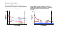
Measurement Techniques ................................................. 21
Understanding Measurement Currents .......................... 21
Insulation measurements above 100 GΩ ....................... 22
Terminals ...................................................................... 23
GUARD terminal, screened leads .................................. 23
Preventive Maintenance ....................................................... 24
Cleaning ........................................................................ 24
Care of the instrument ................................................... 24
Leads ............................................................................ 24
Battery Care .................................................................. 24
Replacing the battery..................................................... 24
MIT1525 battery replacement instructions: ...................... 25
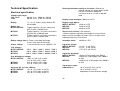
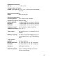
Technical Specification ......................................................... 26
Electrical specification ....................................................... 26
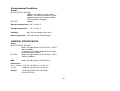
Environmental Conditions ................................................. 28
GENERAL SPECIFICATION ............................................ 28
Repair and Warranty ............................................................ 29
Calibration, Service and Spare Parts ................................ 29
Returning product to Megger UK & USA service centres .. 29
Approved Service Centres ................................................ 30
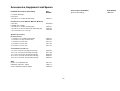
Accessories, Equipment and Spares…………………………..31

5
General description
The new range of Insulation Resistance Testers (IRT) consists
of four models; an entry level 5 kV and three fully featured
units, one 5 kV, one 10 kV and one 15 kV.
Features
• Max resistance is 10 TΩ (5 kV), 20 TΩ (10 kV) and 30 TΩ
(15 kV)
• MIT515 with IR, IR(t), PI and DAR
• MIT525, MIT1025, MIT1525 diagnostic and over voltage
tests - PI, DAR, DD, SV and ramp test.
• Operate and charge on line power/mains (except during
actual test)
• Light weight Li ion battery
• CATIV 600 V safety rating (MIT515, MIT525, MIT1025)
CATIV 1000 V safety rating (MIT1525) – applies to
voltmeter function
• Advanced memory with time/date stamp
• DC and AC voltmeter (30 V to 660 V)
• Large LCD display with backlight
• Download of saved results and logs via isolated USB cable
(MIT525, MIT1025, MIT1525 only)
• PowerDB Lite software included with MIT525, MIT1025
and MIT1525.

6
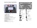
Instrument Controls and Indicators
1. Positive (+) terminal
2. GUARD terminal
3. Negative (-) terminal
4. USB device interface
5. Four arrow buttons and OK button
6. TEST button with associated HV warning lamp
7. Backlight button
8. Central rotary switch
9. Save button – MIT525, MIT1025, MIT1525
10. Test mode rotary switch
11. LED indicating line power / mains
12. Display
13. Power socket
14. Functional earth terminal: 15 kV only
User lock
voltage
Delete records
Timer
Download via
USB
Save
Filter
Open records
Alarm
Battery
Breakdown
mode
Ramp test
Burn mode
Danger HV
Refer to manual
Fuse
Noise detected

7
Preparations for Use
Initial instructions
• Remove instrument, power lead and pouch from the
packing box.
• Clip the test lead pouch to the lid.
• Open the lid and familiarise yourself with the layout and
position of the IEC 60320 power inlet on the left side of
the panel. An isolated USB socket is found on the right
side of the instrument.
• Unpack leads and pack them into the lead pouch.
• Read the product manual, especially the warnings.
• A quick reference is provided in the instrument lid.
• Keep the original packaging for re-use.
Power lead and battery charging
• If the power lead supplied is not suitable for your
line/mains connection, do not use an adaptor. Always
use a power lead fitted with the correct plug.
• Supply voltage: 90 to 265 V rms ac at 50/60 Hz.
• A green LED illuminates when line power/mains is
present.
• The battery will charge as long as the mains supply is
connected, except when a test is in progress.
• For optimum battery life, charge the battery after each
use. Full charge duration is up to 2½ hours but a first
charge time of 3 hours is advised.
• The battery must be charged between 0 ºC and 40 ºC
ambient temperature. If the battery detects a
temperature outside this range the battery symbol will
flash.
Power lead connection table
Connection UK/International USA
Earth/Ground
Yellow/Green
Green
Neutral Blue White
Live (Line) Brown Black
Functional verification
Simply turning on the instrument will initiate a start-up process
and the display will respond. If an error is detected ‘Err’ will be
displayed with an associated error number.
Calibration
The MIT515, MIT525, MIT1025 and MIT1525 are supplied with
a calibration certificate which is automatically generated as
part of Megger’s final test procedure.
UKAS accredited calibration certificates are available from
Megger but this service is chargeable.
Storage
Instruments should be stored in storerooms which meet the
storage temperature and humidity specifications listed in this
document. If charging is incorporated in the storeroom the
room must be well ventilated.

8
Operating Instructions
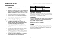
General operation
The MIT515, MIT525, MIT1025, MIT1525 Insulation resistance
testers (IRTs) are primarily controlled by two rotary switches
and a TEST button used to start and stop a test (see section
entitled, ‘Instrument Control and Indicators’). The central rotary
switch includes an ‘OFF’ position; the instrument switches on
by rotating the switch either clockwise or anticlockwise from
this position. A range of test voltages for insulation resistance
tests up to 5 kV for MIT515/MIT525,10 kV for MIT1025 and 15
kV for MIT1525 are available, including a user selectable
voltage range which can be set between 40V or 100 V and
5000 V, 10000 V or 15000 V depending on model. The
‘lockable’ test voltage range can be adjusted in the settings
function.
The settings function is indicated by a spanner symbol and
facilitates lock voltage, low resistance alarm, temperature,
time/date adjustment. A light blue coloured section of the
rotary switch denotes memory functions; open records,
download via USB and delete records. A dedicated save
button is provided on the MIT525, MIT1025 and MIT1525
models and all models have a backlight button.
A second rotary switch controls the insulation test mode
providing for the following tests:
• All models have basic insulation resistance IR, timed
insulation resistance IR(t), Dielectric Absorption Ratio
(DAR) and Polarisation Index (PI) tests.
• MIT525, MIT1025, MIT1525 have additional tests;
Dielectric Discharge (DD), Step Voltage (SV) and ramp
test.
A cluster of directional buttons and an OK button are used in
settings and memory functions. The up/down arrows also
enable the test voltage to be adjusted during a test. Prior to
the start of an IR or IR(t) test, holding down the left arrow
button with a voltage level selected on the central rotary switch
will activate burn mode. Burn mode is deactivated if the
voltage range or mode is changed or by pressing the right
arrow/breakdown button.
Instrument controls are simple to operate. The central rotary
switch incorporates the OFF position. The left hand rotary
switch selects insulation test type (test mode switch). The
TEST button starts and stops a test.
Four arrow buttons and OK facilitate adjustment and selection
of settings, voltages and modes. Breakdown/burn modes are
set using the left and right arrow buttons. Backlight and save
functions are dedicated buttons. All models have backlight and
the MIT525, MIT1025 and MIT1525 have the Save button.

9
Breakdown vs. burn mode
In breakdown mode insulation tests are automatically stopped
when a fault causes the applied voltage to drop rapidly. Burn
mode IR tests ignore breakdown and continue to test the
insulation and are therefore destructive tests. Burn mode is
used to purposely create a carbon track in insulation to
facilitate fault location. Burn mode only operates at test
voltages of 500 V and above.
Voltmeter
A voltmeter is incorporated in the
instrument and measures AC/DC
voltage from 30 V to 660 V. Frequency
(Hz) is measured and displayed for AC
voltages. Voltmeter mode is activated
by switching to ‘V’ mode as illustrated.
Positive and negative terminals are used for the voltmeter
function; do not connect the GUARD terminal when in
voltmeter (V) mode.
To assist user safety, the instrument will automatically switch
to voltmeter mode if a voltage of 50 V or more is connected to
the terminals. The measured voltage will be displayed
accompanied by an intermittent beeper to warn the user that a
dangerous voltage exists.
For further explanation see, “Running an Insulation Test” on
page 11.
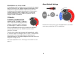
Reset Default Settings
Remove AC source, press OK, backlight buttons and switch
main rotary switch from OFF to setting icon.
7
OFF
250V
500V
1kV
2.5kV
5kV
V
V
TΩ

10
OK
Instrument Control
Initial setup
It is important to setup the Real Time Clock (RTC) on models
MIT525, MIT1025 and MIT1525 to ensure that records saved
in the instrument are time/date stamped correctly. The MIT515
does not require time/date setting. The RTC has a separate
battery to maintain settings even when the primary battery is
removed.
To set the clock and date,
select the settings
function on the central
rotary switch and turn the
mode rotary switch to IR.
Navigate using the
left/right arrows to where
the time and date is displayed.
Set the time using the up and down arrows. Change the hours
and minutes then press OK to save.
Select the day/month format required, i.e. d:m for day:month
or m:d for month:day and press the right arrow button, then set
the date and press OK to save. A tick on the left of the display
indicates that a setting is saved, a cross is displayed during
adjustment indicates that it is not set. Exit settings by changing
the central rotary switch to a different position.
OK
Lock Voltage
The user selectable ‘lock’ voltage range is set by adjusting the
displayed voltage using the up and down arrow buttons. When
the desired voltage is displayed, it is saved, by pressing the
OK button. The setting does not change even if the instrument
is switched off.
Alarm setting
A low resistance alarm sounds when the resistance level of an
insulator reaches the alarm, assuming alarm has been
activated. The default alarm setting is 500 kΩ and inactive (X
is displayed on the right of the display). Set central and mode
rotary switches to the settings and IR positions respectively.
Press the right arrow button once. The low resistance alarm
can be set at the default value by simply pressing the OK
button, or changed to a different alarm resistance level using
the up/down arrow buttons and save it by pressing OK.
Recording temperature
The MIT525 and MIT1025 are able to record insulation
temperature measured by an independent thermometer. If you
do not wish to record temperature do not change the default
setting or reset it if it was previously set.
Move the central rotary switch to point to settings and press
the right/left arrow buttons until ‘tº ---‘ is displayed. The default
setting is no temperature record. This can be changed by
pressing up or down arrows to select either ºF or ºC
temperature entry. Pressing OK will confirm the setting and
result in a prompt for temperature to be entered whenever the
save button is pressed after completing any test. Up and down
arrows facilitate temperature entry in 1 ºC increments /
decrements.
OK

11
Breakdown mode / burn mode
The insulation resistance ‘IR’ test operates
in either ‘Breakdown’ or ‘Burn’ mode.
Default mode is breakdown.
Left and right arrow buttons toggle between
burn and breakdown mode when a voltage
range is selected. Press and hold left
arrow/burn to activate burn mode.
In breakdown mode the test will automatically terminate on
detection of a breakdown to prevent damage to the insulation.
Burn mode disables the normal breakdown detection and
test voltage continues after breakdown of the insulation.
This enables the location of the failure to be seen and
detected acoustically but it is a destructive test.
Due to the potential damage that could occur, the unit
produces two long beeps when starting a test with burn mode
activated.
Running an insulation test
Before testing any reactive load the insulation must be
fully discharged.
15 kV - The functional earth terminal (g
gg
g) must be
connected to ground or a uni-potential bonding point.
Great care should always be taken when connecting the leads
to a system to be tested. Even isolated systems may exhibit
charges or induced voltages and appropriate Safe Working
Practices must be employed.
On connection of the test leads prior to starting a test, any
voltages of 50 V or more will be indicated on the display,
accompanied by an intermittent beeper, (see Voltmeter pg. 9).
This is especially likely in electrically noisy environments.
Should electrical noise be present it will cause a current to flow
through the instrument’s internal discharge resistors. If this
becomes excessive and exceeds instrument rating, damage to
the instrument may result.
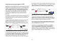
The MIT1525 has been designed to handle high noise currents
up to 6 mA. If current above 6 mA is detected, the instrument
will sound an urgent “warble” tone and be accompanied by the
symbols G .
The instrument should be immediately disconnected from the
supply after discharging the dc test voltage taking care to
ensure Safe Working Practices. (NB very high induced
voltages may be present)
To assist user safety, the instruments will not permit a test to
be started if the induced voltage exceeds 6 mA.
It is possible to adjust the test voltage using the up and down
arrow buttons, either before or during a test. Once a test has
begun, it is advisable to only adjust the voltage in the first 10s
of the test to prevent interference with the capacitive and
absorptive currents in the insulator.
A test can be started by pressing the ‘TEST‘
button for approximately 3 seconds from the test
screen or voltmeter screen. A timer will be
displayed to indicate elapsed time during the
test. The test is stopped, by pressing the TEST button. As
soon as the test is stopped a discharge of the insulator is
automatically initiated. An ‘StP’ indication informs the user that
the test is terminating and after a few seconds the voltage on
the terminals will be displayed. Left and right arrows can be
used to scroll between terminal voltage, last test voltage and
TEST

12
the set range voltage. In the event of a terminal voltage of ≥50
V a voltage and warning will be displayed.
Do not disconnect instrument leads or clamps until the
LED and display warnings are switched off indicating that
the unit under test is discharged! Significant current can
be stored in reactive loads which act as capacitors or
inductors, which can be lethal.
The display shows the final resistance result, capacitance, test
current and Time Constant (TC) in addition to test duration.
On MIT525, MIT1025, and MIT1525 models the result can be
saved by pressing the dedicated save () button after a
resistance or voltage test is complete. The save button will
appear momentarily to confirm the data is saved. If a full test
curve is required the user must select logging by pressing the
save button before starting the test. Data will be logged every
5 seconds for the duration of a resistance test. It is not
possible to log voltages in voltmeter mode.
If temperature entry has been activated a prompt will appear
for the user to enter a temperature reading after IR and IR(t)
insulation tests. DAR, PI, SV, ramp and DD tests will not
prompt for temperature input.
Display backlight is activated by pressing the (J
JJ
J) button. The
backlight button can be pressed a second time to deactivate
the backlight. Automatic deactivation will occur after a preset
timeout period if not deactivated manually.
Memory functions and downloading
Models MIT525, MIT1025 and MIT1525 have advanced
storage, recall and download functions to facilitate
documentation of insulation tests.
Recall results
Setting the central rotary switch to
‘open folder’ position enables the
user to recall saved results
beginning with the most recent
result. Up and down arrow buttons
enable the user to scroll through
results based on a sequential four
digit index. Left and right arrow buttons scroll through a single
result showing all saved test data including time/date. Where
logging has been enabled, only the final result is displayed on
screen. The full result can be viewed by downloading to
PowerDB/PowerDB Lite.
In saved results, the test mode is identified by the icon or
abbreviation of each test on the display. In addition, the open
folder icon is displayed to indicate recall memory mode.
Download results
PowerDB Pro, Advanced and Lite are
Megger’s asset and data management
software packages with integrated
forms for MIT525, MIT1025, MIT1525
instruments.
The default download on the
instrument is a single test log or
summary result. To download all results press an arrow
button.
Detailed instructions on how to interface with PowerDB are
available on the product CD on a document entitled
‘Interfacing MIT525, MIT1025 and MIT1525 to PowerDB’.
PowerDB offers instructions specific to MIT525, MIT1025,
MIT1525 regarding the download procedure. When results are
downloaded the IRT can be disconnected from the PC after
the application releases the port.

13
Deleting results
There are two delete functions; delete a
single result and delete all results.
Select the bin icon on the central rotary
switch. The first record indicated
contains the result of the last test
performed. Up/down arrows navigate
through records and the OK button is
used to select delete where the ‘X’
changes to a tick and the on screen bin icon flashes. A
subsequent press of the OK button activates the deletion.
The default delete is a single test result, press the right arrow
button to select delete all test results from memory.
Real-time output during insulation tests
PowerDB or PowerDB Lite can be used to record real time
data output from the MIT525, MIT1025 and MIT1525 models.
Voltage, current and resistance data is sent at a rate 1 Hz from
the IRT and displayed in real time on a graph, e.g. a plot of
current (µA) versus voltage (kV) for the ramp test.
Before running a test where a real time output is required,
attach a PC running PowerDB Pro, PowerDB Advanced or
PowerDB Lite via a USB cable. Check the product CD
provided with the instrument for a folder named, “Megger
USB.” If this folder exists, use it when starting PowerDB for the
first time to find the driver, if not allow the operating system to
search the internet for the driver. Check the serial port
allocation on Device Manager, and enter the serial port
number allocated when starting PowerDB. PowerDB offers
instructions specific to MIT525, MIT1025 and MIT1525
regarding the real time capture procedure.
Start the application and activate real time data capture in the
form of choice. As soon as the test is started real time data
output will begin. When the test is complete ensure that the
form is saved in PowerDB Pro/Advanced/Lite.

14
PowerDB
PowerDB is software used for the collection and reporting of
data from maintenance and inspection activities performed on
electrical equipment used in the generation, transmission, and
distribution of electric power.
The software includes interfaces for many test instruments and
allows for automated testing and data acquisition, as well as
imports from various file formats. Result and summary reports
can be easily generated.
Three editions of PowerDB are available:
• PowerDB Pro
• PowerDB Advanced
• PowerDB Lite
PowerDB provides a simple and consistent user interface to
many Megger instruments including the DELTA Series Power
Factor Test Sets, 3-Phase TTR units, earth testers, 5 kV, 10
kV and 15 kV insulation resistance testers (IRTs), and many
more. PowerDB Lite is bundled with the Megger’s MIT and S1-
Series. The new S1-Series has remote control capability and a
specific application to enable remote control testing of assets.
Interfacing MIT range to PowerDB
The MIT range has a USB cable connection.
Connect the MIT to a PC via the USB cable provided and
enable the driver for the S1 / MIT to be found via the internet,
or alternatively, load the version supplied on the product CD if
the PC being used has no access to the internet. The
instrument does not need to be powered up to respond to the
driver as it is powered via the USB cable.
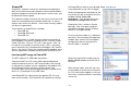
Load PowerDB Lite software from the product CD, this may
take several minutes. Run PowerDB Lite software by clicking
the PowerDB Lite icon on your desktop. Make sure you are
using PowerDB version 10.5 or higher.
Select the appropriate soft button for the
instrument you are testing with from the
window entitled, “Select An
Instrument”. This will take you to the
Instrument Configuration window.
Expand the ‘Ports’ section in Device
Manager. One serial port should be
allocated to ‘Megger Device (COMxx)’
where xx is the port number.
Ensure that port number xx is allocated
correctly in the Instrument Configuration
window, then click the OK to complete
configuration after ensuring that the
correct model is selected.
Select the required test mode from the
Select a Form window and click OK to
continue.
After the form loads, click the ‘zap’ icon
on the toolbar to initialise the instrument.
An ‘OK’ confirmation appears at the top
of the form if communications have been
successful.

15
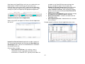
Scroll down the PowerDB form until you see a table with cyan
filled headers. RIGHT CLICK once on one of the cyan
coloured areas to activate the MIT remote control application.
The cyan filled cells represent three phases A, B and C. Right
clicking on a phase will open up the appropriate application.
Import/Live Stream Control Application
When using a MIT the Import/Live Stream Control Application
will launch.
Import/Live Stream Control application enables capture of
live streaming data directly by activating the Start New Live
Streaming function. Results are recorded once a second for
the duration of the test
.
Other functions include:
Save Selected To Form – this soft key saves a
selected test result in top right hand menu to the
current form in PowerDB Lite. Typically three tables are
available in the PowerDB form representing three
phases named A, B and C. Tests listed in the
Import/Live Stream Control application listed under
Test Info can be saved in any form by exiting the
logger (Go Back To Form), right clicking the require
phase in the form and selecting to Save Selected To
Form from the logger
Copy Results to Clipboard function facilitates a copy
of all data to Excel and other popular software
Delete Selected Data – removes test data from the
Test Info section
Start Importing Results – download results saved on
the instrument
Sample Import/Live Stream Control application after a test.

16
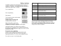
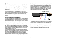
Battery indicator
The battery symbol on the LCD display contains four pairs of
segments. The battery is monitored continuously when the
instrument is turned on. The charge remaining in the battery, is
indicated by segment pairs as follows:
Fully charged battery
50% charged battery
Empty battery
Tests cannot be started, and the battery
may fail at any time
Symbol flashes when there is not
enough charge for a test and the
instrument will turn itself off.
When mains power is present the
indicator shows the battery is being
charged by animating the segments of the bar graph.
A blinking full battery icon indicates that the battery is
prevented from charging due to the temperature being out of
the allowable charge temperature range, 0 ºC to 40 ºC, or that
the battery has failed.
On screen error reporting
Should an error be detected during the operation of the
MIT515, MIT525, MIT1025 or MIT1525 an error code is
reported preceded by ‘Err’ with the read handbook warning.
Error codes are given in the following table.
‘Err’ code
Fault
2 Output voltage over limit
3 FIFO (memory) overflow
4 HV board mismatch with control board setup
5 Battery low error
6 Control board detected inter-board
communication failure
7 Test button stuck
8 Measurement board i2c failed
9 Measurement board detected inter-board
communication failure
10 Isolation power supply cut-out
11 Instrument attempted auto power off but failed
12 HV circuit control fault
If an error occurs do not attempt to repair the instrument.
Obtain a repair number from Megger Instruments Limited,
carefully pack in a suitable box and send the faulty instrument
to the nearest Megger Approved Service Centre, if possible
noting the error that was reported.

17
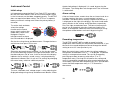
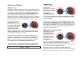
Measurement Modes
‘Spot’ IR test
The spot insulation resistance test (IR) is selected on the test
mode rotary switch. Select the IR setting and then the required
test voltage using the preconfigured voltage ranges on the
central rotary switch or the V
L
user settable/lockable voltage
range. All preconfigured voltage ranges, but not V
L
, are
adjustable using up and down arrow buttons before and during
the test, but the latter should be limited to the first 10 seconds
of IR and IR(t) tests. Press and hold TEST to start the test.
To set the user defined
lock voltage V
L,
turn
the central rotary switch
to settings and the mode
switch to IR. The preset
voltage 5000 V will flash
and can be changed
using the up/down buttons. When the required maximum
voltage is displayed, press the OK button to save the setting.
This setting will remain until it is reset.
Whenever V
L
is selected the set voltage is shown on the
display. The voltage lock is useful when, for example, testing
insulation of XLPE cables that should not be tested above
5000 V. The lock function will ensure it does not exceed the
V
L
voltage within the stated output voltage accuracy.
On test completion, insulation capacitance (C) and the Time
Constant (TC) associated with it is calculated and displayed.
Time Constant (TC) = R
insulation
x C
insulation
Timed IR test
A timed test IR(t) will
automatically
terminate an insulation
test after a preset time.
Default timer is set to 1
minute and is
adjustable within the
settings function. This
is a useful feature which saves the user watching the display
for the full duration of the test and the possibility of missing the
1 minute reading.
Turn the central rotary switch to the settings position. Select
IR(t) on the test mode rotary switch. The default time of 1:00
minute will flash prompting the user to select a new time using
the up/down arrow buttons. Press OK to set test duration and
turn central rotary switch to desired test voltage. Press and
hold TEST to start the test.
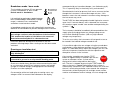
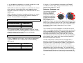
DAR and PI Insulation Tests
DAR and PI tests are
measurements of
resistance over time
expressed as a ratio of
resistance at time t2
divided by resistance
at time t1. The
assumption is that
insulation temperature does not vary widely over the duration
of the test so the resulting DAR and/or PI value are
temperature independent. Testing should be done at or below
40 ºC, 104 ºF for this assumption to hold.
DAR and PI timers t1 and t2 are set when DAR or PI is
selected on the test mode rotary switch with the central rotary
switch in the settings position. Timer t1 is set first followed by
OFF
500V
1kV
2.5kV
5kV
10kV
V
V
TΩ
USB
PI
DD
SV
DAR
IR(t)
IR

18
t2. Up and down arrow buttons are used to change the t1 and
t2 default values and OK confirms each setting.
DAR and PI insulation test voltages are selected on the central
rotary switch by simply aligning the switch opposite to the
required insulation test voltage. Press and hold TEST to start a
DAR/PI test.
DAR is defined as the ratio of insulation resistance at 1 minute
divided by insulation resistance at 30 seconds, although a 1
minute, 15 second DAR is also popular:
DAR = IR
60s
/ IR
30s
Insulation Condition DAR result
Poor
< 1
Acceptable
1
–
1.4
Excellent
1.4
–
1.6
IEEE standard 43-2000, Recommended Practice for Testing
Insulation Resistance for Rotating Machines, defines PI as the
ratio of insulation resistance at 10 minutes divided by
insulation resistance at 1 minute:
PI = IR
10min
/ IR
1min
If IR
1min
> 5000 MΩ the PI may or may not be an indication of
insulation condition and is therefore not recommended by
IEEE std. 43.
Insulation Condition PI result
Poor
< 1
Questionable
1
-
2
Acceptable
2
-
4
Good
> 4
PI results > 1.5 are regarded as acceptable by IEC60085-
01:1984 for thermal class rating A, and PI results > 2.0 for
thermal class ratings B, F and H.
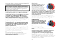
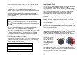
Dielectric Discharge test
The Dielectric Discharge
(DD) or re-absorption
current test operates
during the discharge of
the dielectric under test.
Originally developed by
EDF, France’s power
utility company, it is a
diagnostic insulation test that allows ageing, deterioration, and
voids in the insulation to be assessed. The result is dependent
on the discharge characteristic so the internal condition of the
insulation is tested, largely independent of any surface
contamination.
The insulator must first be charged for a sufficient time to be
stable, i.e. charging and polarization are complete and the only
remaining component of current is leakage current due to the
insulation. On discharge the capacitive component of the
discharge current decays from a high value with a relatively
short time constant of a few seconds. The released absorption
current decays from a lower value with a relatively long time
constant of up to several minutes.
The DD timer defaults to 30 minutes of charging, which is
generally sufficient time for full absorption to take place in an
insulation material. The default test voltage is set to 500 V so
the primary rotary switch must be set at or above 500 V.
The default DD test duration (t1) is 30 minutes insulation test
followed by a fixed 1 minute discharge. The initial 30 minute
period can be adjusted but care should be taken to ensure that
full absorption will take place in the insulation test period. DD
should be selected on the test mode rotary switch and settings

19
on the central rotary switch. Timer t1 is set using the up and
down arrow buttons and OK confirms the setting.
The ‘DD’ test requires the instrument to measure the
discharge current 1 minute after the removal of the test
voltage, which is greater than the primary time constant of the
discharge. On completion of the test, the instrument uses this
measurement along with the test voltage and calculated
capacitance to produce a figure of merit indicating the quality
of the insulation.
DD = I
1min
/(V x C)
where I
1min
is the discharge current in mA one minute after
removal of the test voltage V in Volts and C is the capacitance
in Farads.
DD results can identify excess discharge currents that arise
when a layer of multi-layer insulation is damaged or
contaminated, a condition that will be missed by both the IR
and PI tests. Discharge current will be higher, for a given value
of voltage and capacitance, if an internal layer is damaged.
The time constant of this individual layer will mismatch the
other layers, giving rise to a higher value of current than for
insulation that is ‘good’ in this respect.
Homogenous insulation will have a DD value of 0, while good
multi-layer insulation will have a value up to 2. The following
table is a guide to DD test results:
Insulation Condition DD result
Bad
> 7
Poor
4
-
7
Questionable
2
-
4
Good
< 2
Homogenous
0
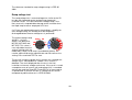
Step Voltage Test
The SV test is a controlled overvoltage test that can be applied
to stator and rotor windings on synchronous and
asynchronous AC motors and the armature and field windings
on DC motors. It is advisable to perform a PI test before an SV
test to determine if the insulation is suitable for overvoltage
testing. If a PI test was performed to verify the winding’s
suitability for over voltage testing, the winding must be
completely discharged before the overvoltage test is
performed.
The SV test is based on the principle that an ideal insulator will
produce identical readings at all voltages, while an insulator
which is being over stressed, will show lower insulation values
at higher voltages.
During the test the applied voltage steps incrementally by one
fifth of the final test voltage each minute for 5 minutes, taking
successive measurements.
Resistance readings for the first four ‘steps’ are displayed
under consecutive time designators ‘1m’ to ‘4m’. The 5 minute
reading is displayed by the main display. If the default 5
minute test duration is changed by the user the four readings
will not show the respective ‘1m’ to ‘4m’ indicators.
The SV test duration
can be adjusted if
desired from the 5
minute default value
using the up/down
arrows and OK to save
the setting.
The step timer will always be set to total test time divided by
five. Too short a step time may result in incorrect readings and
too long a step time may over stress a motor.

20
The reference standard for step voltage testing is IEEE 95-
2002.
Ramp voltage test
The ramp voltage test is an overvoltage test similar to the SV
test but with improved control and warning of potential
insulation failure. The slow continuous voltage ramp is less
likely to result in unpredictable damage to the insulation than
the rapid step increases employed in SV test.
If a PI test was performed to verify the winding’s suitability for
over voltage testing, the winding must be completely
discharged before the over voltage test is performed.
The typical voltage ramp
(dV/dt) is 1 kV/min
which is the default for
MIT525, MIT1025 and
MIT1525. This value is
user adjustable from the
settings function with the
mode rotary switch set to ramp. Up and down buttons are
used to adjust dV/dt to the required rate and OK confirms the
setting. Press and hold TEST to start.
The test will ramp the voltage until it reaches the selected test
voltage unless a breakdown or sudden rise in current is
detected. The result displayed after the test is the final
insulation resistance, voltage and current. If the result is saved
a complete curve of current (µA) and voltage (kV) is recorded
and can be read into PowerDB, PowerDB Lite or converted to
a spreadsheet so that the current vs. voltage curves can be
compared to published curves in IEEE 95-2002.
Page is loading ...
Page is loading ...
Page is loading ...
Page is loading ...
Page is loading ...
Page is loading ...
Page is loading ...
Page is loading ...
Page is loading ...
Page is loading ...
Page is loading ...
Page is loading ...
-
 1
1
-
 2
2
-
 3
3
-
 4
4
-
 5
5
-
 6
6
-
 7
7
-
 8
8
-
 9
9
-
 10
10
-
 11
11
-
 12
12
-
 13
13
-
 14
14
-
 15
15
-
 16
16
-
 17
17
-
 18
18
-
 19
19
-
 20
20
-
 21
21
-
 22
22
-
 23
23
-
 24
24
-
 25
25
-
 26
26
-
 27
27
-
 28
28
-
 29
29
-
 30
30
-
 31
31
-
 32
32


Megger MIT1025 User manual
- Category
- Measuring, testing & control
- Type
- User manual
Ask a question and I''ll find the answer in the document
Finding information in a document is now easier with AI
Related papers
Other documents
-
 EC Line EC-CD-4617D Datasheet
-
Kmart 42959441 User manual
-
Omega Speaker Systems OM-EL-USB-LITE User manual
-
 B&G DAR-04 Operating instructions
-
media-tech MT6208 User manual
-
UNI-T UT07B-EU User manual
-
Fluke 1550C FC 5 kV Digital Insulation Tester User manual
-
Sanwa MG5000 User manual
-
 Seaward Europa Plus User manual
-
Greenlee 5990A Megohmmeter User manual


