Garmin TR-1 Installation guide

Category
Motor vehicle accessories & components
Type
Installation guide

This manual is also suitable for

Garmin TR-1 Gold Marine Autopilot is a versatile and reliable device designed to enhance your boating experience. With its advanced features, the TR-1 Gold provides precise steering control, allowing you to maintain course, steer to waypoints, and navigate with ease. It seamlessly integrates with compatible Garmin chartplotters and marine electronics, enabling you to create and follow complex routes, adjust your course on the go, and monitor your boat's position and heading.

Garmin TR-1 Gold Marine Autopilot is a versatile and reliable device designed to enhance your boating experience. With its advanced features, the TR-1 Gold provides precise steering control, allowing you to maintain course, steer to waypoints, and navigate with ease. It seamlessly integrates with compatible Garmin chartplotters and marine electronics, enabling you to create and follow complex routes, adjust your course on the go, and monitor your boat's position and heading.

Throttle Actuator
Installation Instructions
Suzuki 9.9 HP: 1997- 2004
Suzuki 15 HP: 1997- 2004
OMC 9.9 HP: 2003 and Newer
OMC 15 HP: 2003 and Newer
1
PN 906-1090-01
TR-1 Gold
3
2
4
5
1
Suzuki/OMC Throttle Parts
Item # Part Number Description Qty.
1 130-1090-01 Throttle Actuator Assembly. Suzuki/ OMC 1
2 310-0004-25 #4-40 X 1/4 Phillips Flathead screw 2
3 305-0002-02 Small Tie Wrap 1
4 380-1098-00 Plate, Bell Crank Draw 1
5 380-1099-00 Plate, Bell Crank Spacer 1
3
Tools Needed:
Suzuki/OMC Outboard Motor Service Manual
Manufacture’s Part # 99500-93E02-01E
Vice Grips or Similar
Pliers
Ratchet
12mm socket
10mm socket
Extension
6mm internal Hex Bit (Allen)
Torque Wrench
Hacksaw
#1 Phillips screw driver
#3 Phillips screw driver
Locktite or Similar thread locker
Warning! Please Read. This application can be a difcult throttle installation, and requires
the use of a Torque Wrench in the installation. Since this engine is so tightly packaged, you may wish
to have your Suzuki/OMC dealer install this for you. Read through the instructions completely before
proceeding. If you have any questions, please don’t hesitate to call our technical service advisors.
2
4
Step One:
Disconnect motor from battery and or disconnect safety
lanyard, to prevent motor from starting during throttle
actuator installation
Step Two:
Remove Cover (cowling) from motor.
Step Three:
Remove the right side cover as described in the Ser-
vice Manual.
Figure 1
Figure 2
Figure 3
Step Four:
Remove the carburetor as described in the Service
Manual. Leave the fuel hose attached, as shown in
gure 5.
Figure 4
Figure 5
Figure 6
Step Five:
Remove the outer throttle lever parts. See gures 5
and 6. Note the order and orientation of these parts
as they are removed. See Figure 7.
Figure 7
1. Nut
2. Lock Washer
3. Washer
4. Throttle Valve Shaft lever
5. Brass Shoulder Washer
6. Throttle Arm
(Non-modied)
5
Cut here
Original Part
Modied Part
Step Six:
Remove the return ear of the throttle arm, as
shown in gure 8.
Note: This Modication allows the throttle to be
advanced by either the tiller or remote, or by the
TR-1 Throttle actuator. It will also disable the
“force to idle” feature of the standard throttle.
Figure 8
Replace these parts in the order that
they were removed. (See step seven)
Start rst with the modied throttle
arm.
1. Throttle Arm (Modied) (Figure 9)
2. Brass Shoulder Washer (Figure 10)
3. Throttle Valve Shaft lever (Figure 11)
4. Washer (Figure 12)
5. Lock Washer (Figure 13)
6. Nut (Figure 13)
Figure 9
Step Seven:
Re-assemble the lever assembly starting with the
throttle arm rst. Be sure that the return spring gets
wound down to engage the lever, as it was before the
arm was removed. Re-assemble the remaining pieces
using gures 10, 11, 12, and 13
6
Install Brass Shoulder Washer. See gure 10.
Figure 10
Figure 11
Figure 12
Install Throttle Valve Shaft Lever. See gure 11
Install the rst washer. See gure 12.
7
Figure 13
Figure 14
Figure 15
Install the lock washer, then install the nut. See
gure 13.
Retighten the lever assembly. See gure 14.
Note: If you did not change carburetor
adjustment screws, they should not need re-
adjustment
Step eight:
Re-Install the carburetor according to the directions in the
service manual.
If you decide to remove the carburetor by detaching the
carburetor manifold from the head. Re-torque those bolts to
10 Nm/7 Ft. Lb.
8
Step Nine:
Remove the head bolt, as indicated in gure 16.
Figure 16
Figure 17
Figure 18
Route the water hose inlet behind, or under the
water inspection hose.
Use the removed cylinder head bolt to mount the
throttle actuator bracket as shown.
Torque bolt 30Nm/21.5 lb. ft.
9
Step Ten:
Tie wrap the water inlet line to the leg of the actuator
mounting bracket as shown in gure 19.
Figure 19
Step Eleven:
Mount the throttle bell crank. Put the radius of the
bracket against the backside (spring side) of the white
plastic Spring Bushing. It goes in between the spring
and the head of the bushing. See gure 20.
Figure 20
Figure 21
Rotate the Bracket counter clockwise and
tip the bottom out slightly, and the top right
in, so it will go under the throttle return
spring lever. Engage the bent tab of the
spring lever in the slot of the bell crank
lever. See gure 21.
10
Figure 22
Figure 23
Figure 24
Step Twelve:
Use thread locker (locktite) on screw. Put the draw
plate hole over the buttery shaft end and just start
the screw on the short (upper left) end. See gure 22
Place the spacer plate with its hole lined up with
the threaded hole of the bell crank, and between
the crank and the face of the spring lever. See
gure 23.
Use thread locker on screw and put the second
screw through the draw plate long end, through
the spacer plate hole, and into the bell crank
threaded hole. Tighten both draw plate screws.
Check to be sure the throttle rotates and returns to
idle stop freely. See gure 24
11
Figure 25
Figure 26
Figure 27
Step Thirteen:
Push the actuator shaft (threaded rod) to the fully
extended position. Adjust the throttle pull string
so there is a 1/16 of an inch bow of slack at full
idle and use the screw to lock the string in this
position.
Step Fourteen:
Connect to Electrohydraulic unit at number 2. Be
sure to seat this connection rmly.
(Other connections per autopilot installation
manual.)
Step Fifteen: Test Actuator
Turn the system on by pressing and releasing
the Deckmount button (On/Off switch). The
Deckmount will continue to ash for 30
seconds, but the throttle functions will work
while it is ashing. Press and hold the up
arrow on the handheld as shown in gure 27,
until the actuator rod (threaded rod) is fully
retracted. It should move freely without any
binding.
12
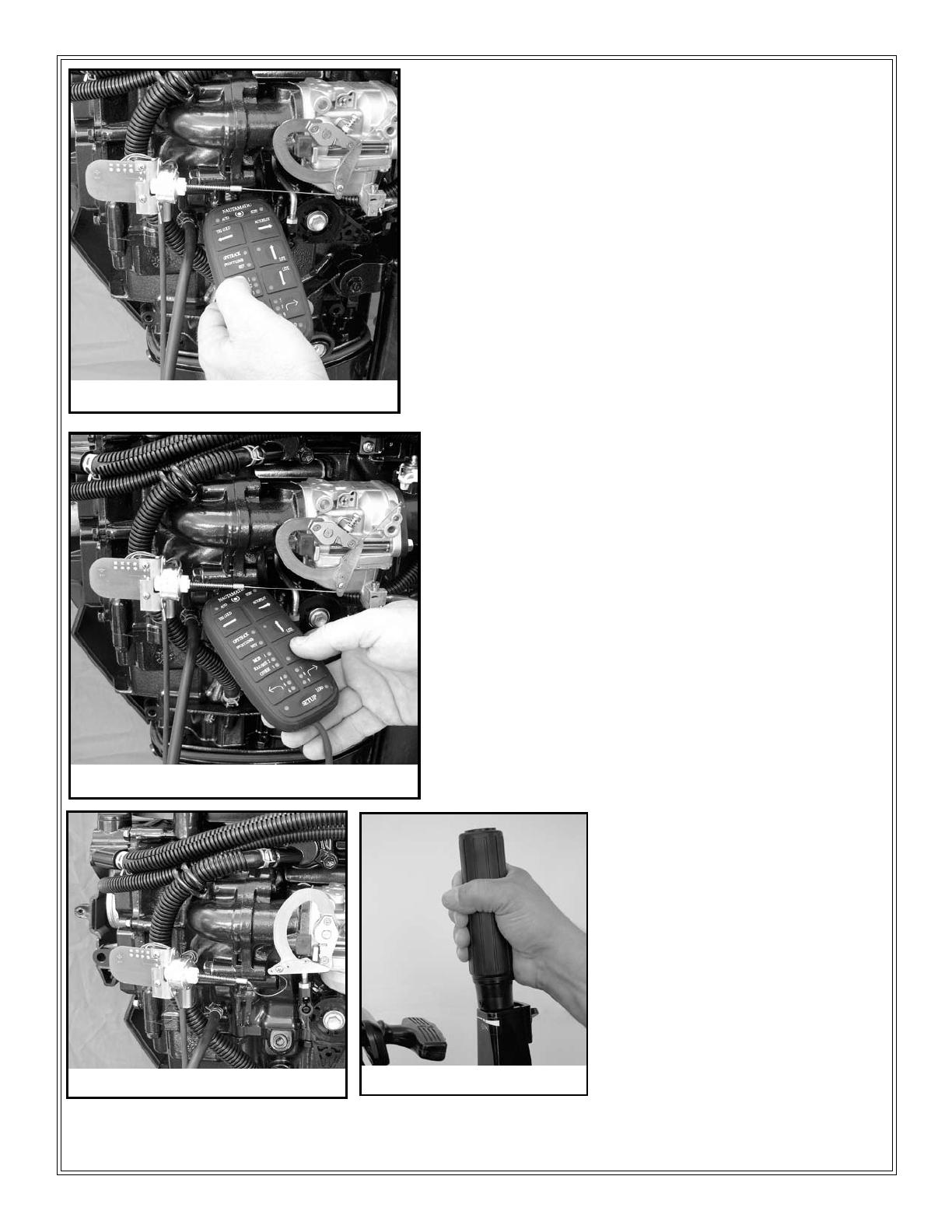
Now test the Idle/Resume function by pressing and
releasing the Idle/Res on the handheld. See gure 28.
Be sure the Carburetor returns to the full Idle Position.
Press the Idle/Res button again, the throttle should
advance until the actuator is fully retracted.
Press the down arrow till the actuator rod is out
about 1/4 inch. Press the Idle/Resume to conrm
function. Re-adjust string (or parts) if necessary.
Return throttle to Idle position by pressing the Idle/
Res button.
Figure 28
Figure 29
Figure 30
Use the factory standard throttle to
manually advance and reduce the
throttle setting. See gure 31.
Note: Which ever mechanism is set
for the highest throttle setting, will
have control of the carburetor; tiller,
remote throttle, or TR-1 throttle
control. If your motor does not idle
down fully when using the autopilot
throttle, check your manual throttle
to be sure it is at full Idle.
Figure 31
13
Step Sixteen:
Re-install the lower covers of the motor per the
service manual.
Secure wire in a position where it will not get
damaged, cause problems with other parts, or get
pinched between the motor frame and the covers.
Step Seventeen:
Route the throttle control wire out of the motor covers
and to the Electrohydraulic Unit. Secure the wire and
be sure the routing to the box allows for full travel of the
motor in both directions plus tilt.
Replace cover (cowling). Re-connect the lanyard and
re-connect motor to battery.
Figure 32
Figure 33
14
Testing the Actuator Functions:
Please refer to the startup section of your owner’s manual before operating your handheld and running the
throttle actuator.
1. With the outboard in the water, or with a proper coolant ush device connected, start the outboard and
let it warm up to operating conditions. Be prepared to kill the outboard ignition if the idle speed is too
high when the engine starts.
2. Using the UP ARROW button on the Handheld verify that the engine rpm’s go up. Using the IDLE/
RESUME button on the handheld verify that the engine returns to idle. Check the throttle up and down
several times along with the idle/res and verify that you don’t have any problems.
1 / 1

Garmin TR-1 Installation guide

Category
Motor vehicle accessories & components
Type
Installation guide
This manual is also suitable for

Garmin TR-1 Gold Marine Autopilot is a versatile and reliable device designed to enhance your boating experience. With its advanced features, the TR-1 Gold provides precise steering control, allowing you to maintain course, steer to waypoints, and navigate with ease. It seamlessly integrates with compatible Garmin chartplotters and marine electronics, enabling you to create and follow complex routes, adjust your course on the go, and monitor your boat's position and heading.

Ask a question and I''ll find the answer in the document

Finding information in a document is now easier with AI

Ask the document