Page is loading ...

®®
2300 / 2600X / 4600X
AMPLIFIERS
OWNER'S MANUAL
Series 1

Dear Customer,
Congratulations on your purchase of America’s finest brand of car audio
amplifiers. At Rockford Fosgate we are committed to musical reproduction
at its best, and we are pleased you chose our product. Through years of
engineering expertise, hand craftsmanship and critical testing procedures
we have created a wide range of products that reproduce music with all the
clarity and richness you deserve.
For maximum performance we recommend you have your new Rockford
Fosgate product installed by an Authorized Rockford Fosgate Dealer, as we
provide specialized training through Rockford Technical Training Institute
(RTTI). Please read your warranty and retain your receipt and original
carton for possible future use.
To add the finishing touch to your new Rockford Fosgate image order your
Rockford accessories, which include everything from T-shirts and jackets to
hats and sunglasses.
To get a free brochure on Rockford Fosgate products and Rockford accesso-
ries, please call 1-800-366-2349 or FAX 1-602-894-1528 in the U.S. For
Canada, call Korbon Trading at 905-567-1920. For International orders FAX
+001-1-602-967-8132 or call +001-1-602-967-3565.
The serial number can be found on the outside of the box. Please record it
in the space provided below as your permanent record. This will become
useful in recovering your amplifier if it is ever stolen and serve as verifica-
tion of your factory warranty.
Serial Number: ____________________
Model Number:____________________
PRACTICE SAFE SOUND™
CONTINUOUS EXPOSURE TO SOUND PRESSURE LEVELS OVER 100dB
MAY CAUSE PERMANENT HEARING LOSS. HIGH POWERED
AUTOSOUND SYSTEMS MAY PRODUCE SOUND PRESSURE LEVELS
WELL OVER 130dB. USE COMMON SENSE AND PRACTICE SAFE SOUND.

TABLE OF CONTENTS
Specifications.................................................................................... 1
Introduction ...................................................................................... 3
Operating Features ..................................................................... 3
Design Features................................................................................. 4
Installation Considerations ................................................................ 6
Tools Needed ............................................................................. 7
Battery & Charging............................................................................ 7
Mounting Locations .......................................................................... 7
Trunk Mounting.......................................................................... 7
Passenger Mounting ................................................................... 8
Wiring the Series 1............................................................................ 8
Power......................................................................................... 8
Ground....................................................................................... 8
Remote Turn-on ......................................................................... 8
Input........................................................................................... 9
Speakers ..................................................................................... 9
Bridged/Mono Configuration ...................................................... 9
Active Crossover Mode Selections for the 2600x and 4600x ........... 10
Crossover Frequency Settings ................................................... 10
Wiring Diagrams............................................................................. 11
Troubleshooting .............................................................................. 17
Dynamic Power Measurements....................................................... 20
Warranty Information...................................................................... 22

– 1 –
SPECIFICATIONS
Series 1 2300 Series 1 2600x Series 1 4600x
Dynamic Power Rating (IHF 202 Standard) - Measured at 14.4 Voltage
1
Bridged/Mono into a 4Ω Load 90 Watts 180 Watts 180 Watts x 2
Per channel into a 2Ω Load 45 Watts 90 Watts 90 Watts x 4
Per channel into a 4Ω Load 30 Watts 60 Watts 60 Watts x 4
Continuous Power Rating (IASCA Standard) - Measured at 12.6 Battery Voltage
RMS continuous power per channel, all channels
driven into a 4Ω load from 20 to 20,000 Hz with less
than 0.08% Total Harmonic Distortion (THD) 15 Watts 30 Watts 30 Watts x 4
RMS continuous power per channel, all channels
driven into a 2Ω load from 20 to 20,000 Hz, with less
than 0.3% Total Harmonic Distortion (THD) 30 Watts 60 Watts 60 Watts x 4
RMS continuous power bridged/mono into a 4Ω load
from 20 to 20,000 Hz with less than 0.3% Total
Harmonic Distortion (THD) 60 Watts 120 Watts 120 Watts x 2
1
See Appendix A - Dynamic Power Measurements for information on these specifications.

– 2 –
Series 1 2300 Series 1 2600x Series 1 4600x
Signal-to-Noise Ratio Over 105 dB A weighted
Bandwidth 10 Hz to 100 kHz ± 3dB
Damping Factor @ 4Ω At output connector - Over 200
Frequency Response 20 Hz to 20 kHz ± 0.5dB
IM Distortion (IHF) Less than 0.05%
Input Impedance 20k ohms
Input Sensitivity (250 mV - 1 Volt)
Protection Internal analog-computer output protection circuitry limits power in case of
overload. Thermal switch shuts down the amplifier in case of overheating.
Crossover Card N/A 12 dB/octave with selectable
High-Pass, Low-Pass and Full Range
Battery Fusing Rates 10 Amps 20 Amps 30 Amps
(External to Amplifier)
Fuse Type ATC ATC ATC
Dimensions 7.9” (20.07cm) W 7.9” (20.07 cm) W 7.9” (20.07cm) W
5.1” (12.95cm) L 6.1” (15.49cm) L 9.1” (23.11cm) L
2” (5.08cm) H 2” (5.08 cm) H 2” (5.08 cm) H
Specifications subject to change without notice.

– 3 –
INTRODUCTION
This manual provides information on the features, installation and
operation of the Series 1 2300, 2600x and 4600x Amplifiers. We
suggest you save this manual for future reference.
We strongly recommend you have your Authorized Rockford Fosgate
Dealer and Service Center install your new Series 1 amplifier. If you
do choose to install your Series 1 amplifier yourself, please be sure to
read the entire manual before beginning.
OPERATING FEATURES
The Series 1 stereo power amplifiers provide state-of-the-art sound in
cars, vans, boats, or wherever a high current 12 volt power source is
available. Features include:
Discrete Surface Mount Technology – a manufacturing method that
allows the packaging of complex circuitry in small areas, reducing
noise and crosstalk for lower distortion.
Active Electronic Crossover Module – built into the 2600x and 4600x
features 12dB/octave Butterworth filters. The independent crossover
modes in these plug-in modules allow for various configuration
possibilities.
N-Type V-FET Output Drive Circuitry– delivers music with lower
noise and distortion while maintaining a higher slew rate, increased
efficiency and higher power output capability than most amplifiers of
this class.
High Current/High Voltage Output – delivers the power needed for
all listening levels and music frequencies to hear every note.
Pulse Width Modulated (PWM) DC/DC Non-Regulated Power
Supply – assures wider dynamic headroom than the more common
regulated power supplies.
High or Low Level Adjustable Input Sensitivity – permits maximum
compatibility with source units. This allows adjustment of the input
sensitivity level of the power amplifier for RCA (preamp level) or
speaker (high level) inputs.
Real Time Power Protection (R.T.P.P.) – allows for the greatest power
output under all load conditions. When output reaches an unsafe
level it will be reduced, unlike current limiting which often causes
premature protection or failure to protect at all.

Gold-Plated Connectors – of high quality to provide lower resistance
and better reliability.
Series 1 Housing – The extruded aluminum heatsink design of the
Series 1 was designed for high performance cooling.
– 4 –
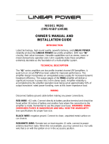
2.
for 4600x model
1.
3.
4.
1. Low Level RCA Input Connectors
The amplifier’s signal input female RCA pin jacks should be
connected to the source unit’s signal outputs with high quality
RCA cables. The connectors are gold plated to eliminate the
possibility of corrosion that can cause signal deterioration.
2. High Level Speaker Input Connectors
These connectors are used to connect to a source unit that does
not provide low level RCA outputs. This connector accepts 1/8"
spade lugs. Do not attempt to solder wires directly to this
connector.
3. LED Power Indicator
The LED illuminates when the unit is in operation.
4. Input Gain Control
This control is factory preset to 500 millivolts to match most radios
and is variable from 250 millivolts to one volt.
(More than likely
it will not need adjusting.)
If just a little movement of the volume control from the source unit
drives the amplifier into distortion, reduce the input gain control
so that the distortion doesn’t start until the source unit volume
control is at about 3/4 of its rotation.
DESIGN FEATURES
Input/LED Side

GND
AP
B+
+R– +L– – R+ – L+
Bridged
Bridged
–
+
– +
– 5 –
for 4600x model
5. Power/Speaker Connectors
The gold-plated terminal block connectors are:
GND Supplies ground to the amplifier.
AP The amplifier is turned on by connecting the remote turn-
on wire to the source unit's “Auto Antenna” or remote
turn-on lead, either of which should go to +12 volts when
the source unit is activated.
B+ Supplies power to the amplifier.
+R– Connect the Right and Left channel outputs to the
speakers.
The terminal block connector accepts wire sizes from 10 gauge
to 20 gauge. *
Spade connectors are not needed because of the design of the
connector. The installer should be careful not to allow wires to
fray or touch. The recommended strip length is 1/4" (.635cm).
*Rockford Fosgate’s Perfect Interface line of accessories includes high
quality power and speaker wire, gold-plated RCA interconnecting cables
and other products to complete your installation. Ask your Authorized
Rockford Fosgate Dealer about Perfect Interface.
Power/Speaker Side
+L–

INSTALLATION CONSIDERATIONS
– 6 –
This section focuses on some of the vehicle considerations for
installing your new Series 1 amplifier. Checking your battery and
current sound system, as well as pre-planning your system layout and
best wiring routes will save installation time. When deciding how to
lay out your new system, be sure that each component will be easily
accessible for making adjustments.
Before beginning any installation, be sure to follow these simple
rules:
1. Be sure to carefully read and understand the instructions before
attempting to install the amplifier.
2. For safety, disconnect the battery ground cable prior to begin-
ning the installation process.
3. For easier assembly, we suggest you run all wires prior to
mounting your amplifier in place.
4. Use only quality connectors for making connections. See your
Authorized Rockford Fosgate Dealer for Perfect Interface wire
enhancements.
5. Think before you drill! Be careful not to cut or drill into gas tanks,
fuel lines, brake or hydraulic lines, vacuum lines or electrical
wiring when working on any vehicle.
6. Never run wires underneath the vehicle. Running the wires
inside the vehicle provides for the best protection.
7. Avoid running wires over or through sharp edges. Use rubber or
plastic grommets to protect wires routed through holes in metal.
8. ALWAYS protect the battery and electrical system from damage
with proper fusing. Install a fuseholder and fuse within 18” (45.7
cm) of the battery terminal to safeguard from possible damage or
injury. This fuse and fuseholder is included with the Series 1
amplifier. (See installation instructions on page 8.)
9. Grounding connections should be as short as possible and
always connected to metal that is welded to the main body, or
chassis, of the vehicle.

– 7 –
TOOLS & SUPPLIES NEEDED
Wire Cutters Phillips Screwdrivers
Wire Strippers Flat Blade Screwdrivers
Wire Crimpers Battery Post Wrench
Voltmeter Electric Hand Drill with assorted bits
Power Wire - [10-12 AWG; approx. 17’ (518.72 cm)]
Grounding Wire - [10-12 AWG.; max. length 1.5’ (45.72 cm)]
Remote (AP) Turn-On Wire - [18 AWG; approx. 12’ (365.76 cm)]
Assorted wire connectors
In-line butt connectors that match power and ground wire AWG
3/8" (.953cm) Battery Ring Terminal
1/4" (.635cm) Ground Terminal
1-1/2" (3.81cm) #8 Pan Head Mounting Screws (4)
Series 1 amplifiers will naturally put an extra load on your battery and
charging system. We recommend you check your alternator capac-
ity to ensure ample charging capability to handle the additional load
of your new Series 1 equipment. Stock electrical systems in good
condition will typically handle the extra load of any individual Series
1 unit without problems, although battery and alternator life may be
slightly reduced. If problems arise, we suggest you first check the
charging system, then use a heavy duty battery and/or a high output
alternator.
The mounting location and position of the Series 1 will have a great
effect on its ability to dissipate the heat generated in normal opera-
tion. The Series 1 has a heatsink designed for heat dissipation and
internal overheating shutoff circuitry to avoid overheating. The
amplifier is reasonably tolerant of mounting variations, however,
care should be taken to ensure adequate ventilation.
TRUNK MOUNTING
The temperature inside a trunk can reach as high as 175° F (80° C)
during the summer months. Since the thermal shutoff point for the
Series 1 is 195° F (90° C), it is easy to see that the amplifier must be
mounted for maximum cooling capability. Mounting the amplifier
on the floor or under the rear parcel tray prevents sufficient convec-
tional air flow cooling. Mounting the unit vertically on a surface with
the fin grooves running up and down usually results in the best
cooling.
MOUNTING LOCATIONS
BATTERY AND CHARGING

– 8 –
PASSENGER MOUNTING
Under the seat or floor mounting will work as long as there is a
minimum of 1” (2.5 cm) of air gap above the amplifier heatsink.
Vertical mounting of the amplifier is still the best.
Caution! Be sure to avoid running the power wires near the low
level input cables, antenna, sensitive equipment or harnesses. The
power wires carry substantial currents and could induce noise.
1. Power – The gold B+ terminal must be connected
directly
to the
positive (+) terminal of the battery with an appropriate size wire.
(See the Specifications for more information.) This provides a
power source with a low voltage drop and low noise.
Be sure to use the supplied fuse and fuseholder within 18”
(45.7cm) of the battery’s positive terminal. Failure to do so may
cause damage to the vehicle and the amplifier.
WIRING THE SERIES 1
Note: You will need to cut the wire loop that
is attached to the fuse holder in half and
splice the fuse into the power line using
appropriate in-line butt connectors.
If the power wire must be extended beyond
17’ (518.16 cm), we recommend the use of 10
gauge stranded wire.
Cut
here
X
2. Ground – The GND terminal grounds the amplifier and is
connected to the chassis of the vehicle. When grounding, scrape
paint off metal to ensure a good, clean ground connection. To
prevent ground loops, we recommend you refrain from extending
the ground wire beyond 18” (45.72 cm) in any installation.
3. Remote Turn-On – The Series 1 amplifiers are turned on by
supplying positive (+) 12 volts to the AP terminal. Usually the
terminal is connected to the source unit’s “Accessory” or “Auto
Antenna” lead, either of which will go to +12 volts when the
source unit is activated.
Although the majority of high quality automotive source units
have an Accessory or Antenna output, there may be exceptions.
If the source unit has no Auto Antenna lead (or if the Auto Antenna
goes down during tape/CD operation), we recommend a switch
in the car with one terminal connected to +12 volts and the other
to the Series 1 AP lead. This will allow you to engage the amplifier
manually.

– 9 –
4. Input – The amplifier’s signal input RCA jacks should be con-
nected to the source unit’s signal outputs with high-quality
braided or double-shielded interconnecting RCA cables.
Note: Be sure to route the Series 1 signal input cable away from
the main power wire and the car’s wiring harnesses to avoid
noise coupling.
If the source unit does not utilize RCA cables, connect the left and
right positive speaker output wires from the source unit to the
amplifier’s High Level Speaker Input Connector. The center pin is
then connected to the chassis of the source unit.
5. Speakers – Series 1 amplifiers are rated for safe operation into
loads of 2Ω or greater in stereo mode, or 4Ω in bridged/mono
configurations. The primary loads on any amplifier come from
directly connected speakers without using capacitors. The mea-
sured resistance for each side should not be less than 2Ω stereo or
4Ω bridged/mono.
6. Bridged/Mono Configuration – The Series 1 amplifiers are ca-
pable of bridged/mono configurations.
This configuration enables you to:
• Run a single woofer with stereo satellites
• Run two bridged amplifiers as a high power stereo system
• Run one amplifier with a bridged/mono woofer and another
as a high-frequency stereo amp, etc.
Note: The 4600x allows the above 3 configurations all in one.
For more information refer to the wiring diagrams beginning on
page 14.
Note: To bridge the amplifier, use the L+ and R– speaker
connectors.
CAUTION! Series 1 amplifiers are not recommended for imped-
ance loads below 2Ω stereo or 4Ω bridged/mono.
Be sure to observe proper speaker terminal polarity throughout
the system. It is critical for the Series 1 to use the correct negative
terminal for right and left channels, since the RIGHT NEGATIVE
(-) TERMINAL is the “hot” terminal for the right speaker. DO
NOT chassis ground any of the speaker leads as unstable opera-
tion may result.

– 10 –
ACTIVE C ROSSOVER M ODE SELECTIONS FOR
THE
2600X AND 4600X
The Series 1 2600x and the 4600x amplifiers feature a selectable
electronic crossover. One module controls two output channels that
can be configured in a High-Pass, Low-Pass, or Full Range (factory
default) position. (Note: The 4600x has 2 modules as it is a 4-channel
amplifier). Selection is made by positioning a removable module
card. Both the 2600x and 4600x are shipped with 100Hz 12dB per
octave Butterworth aligned crossover modules. Additional crossover
frequency modules are available from your Authorized Rockford
Fosgate Dealer.
Note: The factory default setting is Full Range.
CROSSOVER FREQUENCY SETTINGS
To change the crossover mode, remove the crossover module from
the housing. Rotate the module to the desired setting and gently push
the module back into the amplifier housing as shown on the diagram
on the back of the amplifier.
Example:
The 2600x is shipped with a 100Hz module. With the
module in the Full Range setting, the amplifier will pass through all
20Hz - 20kHz frequencies.
In the Low-Pass setting, only those frequencies below 100Hz will
pass through the amplifier.
In the High-Pass setting, only those above 100Hz will pass through
the amplifier.

– 11 –
WIRING DIAGRAMS - 2300 / 2600X
2300/2600X BASIC SYSTEM
–+
Series 1
2300
2600x
– +
Source Unit
4Ω (2Ω min.)
Right Full Range
4Ω (2Ω min.)
Left Full Range
*Xover Module
(2600x only)
Full Range Position
GND
AP
B+
– L +
– R +
*See page 10 for proper crossover use.
Left Right Power
Left GND Right
High Level Inputs
Gain

– 12 –
2300/2600X 3-WAY STEREO/MONO SYSTEM
– +
– +
•
•
•
•
MX
MX
+ –
TX
– +
TX
••
– +
Source Unit
Series 1
2300
2600x
*Xover Module
(2600x only)
Full Range Position
– R +
– L +
GND
AP
B+
Tweeter Tweeter4Ω
Right Midrange
4Ω
Left Midrange
6.6mH Coil
4Ω Subwoofer
*See page 10 for proper crossover use.
Left Right Power
Left GND Right
High Level Inputs
Gain

– +
– +
•
•
•
– +
+ –
TX
TX
MX
MX
– +
Series 1
2600x
•
Series 1
2600x
– 13 –
See page 10 for
proper crossover use.
2600X 3-WAY BI-AMPLIFIED SYSTEM
Source Unit
High Pass
Left GND Right
High Level Inputs
Gain
Left Right Power
GND
AP
B+
– R +
– L +
TweeterTweeter
4Ω
Right Mid-Woofer
4Ω
Left Mid-Woofer
Left GND Right
High Level Inputs
Gain
Left Right Power
4Ω Subwoofer
GND
AP
B+
– R +
– L +
Amp 2
Amp 1

WIRING DIAGRAMS - 4600X
– 14 –
The following pages show some examples for wiring the Series 1 4600x
amplifier to your vehicle's speaker system.
+ –
– +
GND
AP
B+
+R– +L– – R+ – L+
+ – + –
Series 1
4600x
LEFT RIGHT POWER LEFT
LEFT GND RIGHT LEFT GND RIGHT
REAR
CROSSOVER
FRONT
CROSSOVER
RIGHT
HIGH LEVEL INPUTS
GAIN
FRONT
HIGH LEVEL INPUTS
GAIN
FRONT
4600X FRONT/REAR FADING
FULL RANGE SYSTEM
Source Unit
4Ω (2Ω min.)
Right Mid-Woofer
4Ω (2Ω min.)
Right Mid-Woofer
4Ω (2Ω min.)
Left Full Range
4Ω (2Ω min.)
Right Full Range
See page 10 for proper crossover use.

– 15 –
4600X 3-WAY MULTI-CHANNEL
STEREO/BRIDGED MODE
See page 10 for proper crossover use.
+ –
– +
+ –
•
•
•
•
TX
– +
TX
– +
GND
AP
B+
+R– +L– – R+ – L+
Bridged
Series 1
4600x
LEFT RIGHT POWER LEFT
LEFT GND RIGHT LEFT GND RIGHT
REAR
CROSSOVER
FRONT
CROSSOVER
RIGHT
HIGH LEVEL INPUTS
GAIN
FRONT
HIGH LEVEL INPUTS
GAIN
FRONT
4Ω Subwoofer
Tweeter
Tweeter
4Ω (2Ω min.)
Right Mid-
Woofer
4Ω (2Ω min.)
Left Mid-
Woofer
Source Unit

– 16 –
4600X 2 CHANNEL BRIDGED
LOW PASS
See page 10 for proper crossover use.
Source Unit
+ –
– +
GND
AP
B+
+R– +L– – R+ – L+
Bridged Bridged
Series 1
4600x
LEFT RIGHT POWER LEFT
LEFT GND RIGHT LEFT GND RIGHT
Rear CrossoverFront Crossover
RIGHT
HIGH LEVEL INPUTS
GAIN
FRONT
HIGH LEVEL INPUTS
GAIN
FRONT
Front
Xover Module
Low-Pass Position
Rear
Xover Module
Low-Pass Position
4Ω Subwoofer
4Ω Subwoofer

–17 –
TROUBLESHOOTING
This troubleshooting guide is intended to assist you with certain
problems which may occur. If you still encounter problems, see your
Authorized Rockford Dealer for assistance.
Problem
Amplifier will not play — Remote Turn-on light is off.
Solution
1. Check the DC voltage at the amplifier’s B+ terminal with a
voltmeter. The voltage should measure between 11.5V - 15.5V.
If voltage is
not
found, check the battery, fuse, fuse housing and
wire connections. Fix, repair, or replace accordingly.
2. If the amplifier still does not play, check the voltage at the
amplifier’s remote turn-on lead. The voltage should measure
between 11V - 15V.
a. If voltage is above or below the prescribed measurements,
check for proper connections and have the head unit checked
by an Authorized Dealer or Service Center.
b. If the remote turn-on current draw from the head unit is
connected to multiple amps and/or electronics, the current
draw may be too great. Check for proper connections. (Use
a relay to suppress the excessive current draw.)
Problem
Amplifier will not play — Remote Turn-on light is on:
Solution
1. Unplug the head unit and test the amplifier with another working
source unit (i.e., bench-test radio, walkman, etc.). If the amplifier
plays, check the in-dash leads for cuts, breaks and/or shorts.
2. If the amplifier still does not play, disconnect the existing speakers
and connect a set of test speakers to the output of the amplifier
(any type of speaker will do - i.e., simple home box type,
bookshelf, raw speaker, etc.). If the amp plays, check for shorts
or blown voice coils in the vehicle’s speaker system.
/