
DE’LONGHI
COOKING
INSTALLATION and SERVICE INSTRUCTIONS
USE and CARE INSTRUCTIONS
DEF905E
CERAMIC COOKER
distributed by
DeLonghi Australia Pty Ltd
DeLonghi New Zealand Ltd

2
Dear Customer,
Thank you for having purchased and given your preferen-
ce to our product.
The safety precautions and recommendations reported
below are for your own safety and that of others. They will
also provide a means by which to make full use of the fea-
tures offered by your appliance.
Please keep this booklet in a safe place. It may be useful
in future, either to yourself or to others in the event that
doubts should arise relating to its operation.
This appliance must be used only for the task it has
explicitly been designed for, that is for cooking fo-
odstuffs. Any other form of usage is to be considered
as inappropriate and therefore dangerous.
The manufacturer declines all responsibility in the
event of damage caused by improper, incorrect or illo-
gical use of the appliance or be faulty installation.
PRODUCT LABEL
This appliance has been designed and constructed in accordance with the following codes
and specications:
AS/NZS 60335.1 General Requirements for Domestic electrical appliances
AS/NZS 60335.2.6 Particular Requirements for Domestic electrical cooking appliances
AS/NZS CISPR 14.1 Electromagnetic Compatibility Requirements.

3
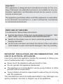
Important:
This appliance is designed and manufactured solely for the coo-
king of domestic (household) food and is not suitable for any non
domestic application and therefore should not be used in a com-
mercial environment.
The appliance guarantee will be void if the appliance is used within
a non domestic environment i.e. a semi commercial, commercial
or communal environment.
FIRST USE OF THE OVEN
It is advised to follow these instructions:
■ Furnish the interior of the oven as described at chapters “USE
AND CARE” and “CLEANING AND MAINTENANCE”.
■ Switch on the empty oven on max to eliminate grease from the
heating elements.
■ Let the oven cool down and clean the interior of the oven with a
cloth soaked in water and neutral detergent, then dry carefully.
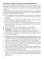
IMPORTANT PRECAUTIONS AND RECOMMENDATIONS FOR
USE OF ELECTRICAL APPLIANCES
Use of any electrical appliance implies the necessity to follow a se-
ries of fundamental rules. In particular:
■ Never touch the appliance with wet hands or feet.
■ Do not operate the appliance barefooted.
■ The appliance is not intended for use by young children or inrm
persons without supervision.
■ Young children should be supervised to ensure they do not play
with the appliance.
The manufacturer cannot be held responsible for any damages cau-
sed by improper, incorrect or illogical use of the appliance.

4
IMPORTANT PRECAUTIONS AND RECOMMENDATIONS
After having unpacked the appliance, check to ensure that it is not
damaged and that the oven door closes correctly. In case of doubt,
do not use it and consult your supplier or a professionally qualied
technician.
Packing elements (i.e. plastic bags, polystyrene foam, nails, packing
straps, etc.) should not be left around within easy reach of children,
as these may cause serious injuries.
■ Some appliances are supplied with a protective lm on steel and
aluminium parts. This lm must be removed before using the
appliance.
■ Do not attempt to modify the technical characteristics of the ap-
pliance as this may become dangerous to use.
■ Do not carry out cleaning or maintenance operations on the ap-
pliance without having previously disconnected it from the elec-
tric power supply.
■ After use, ensure that the knobs are in the off position.
■ Keep children away from the appliance when it is in use.
■ WARNING: Accessible parts will become hot when in use. To
avoid burns and scalds, young children should be kept away.
■ Young children should be supervised to ensure that they do not
play with the appliance.
■ Children, or persons with a disability which limits their ability to use
the appliance, should have a responsible person to instruct them
in its use. The instructor should be satised that they can use the
appliance without danger to themselves or their surroundings.
■ During and after use of the appliance, certain parts will become
very hot. Do not touch hot parts. Care should be taken to avoid
touching heating elements inside the oven.
■ Make sure that electrical cables connecting other appliances in
the proximity of the cooker cannot come into contact with the hob
or become entrapped in the oven door.
■ Do not allow heavy or sharp objects to drop on the glass cera-
mic hob. If the hob is cracked or otherwise damaged by falling
objects etc., disconnect the electrical power cord and call Custo-
mer Service.

5
■ Do not scratch the hob with sharp objects. Don’t use the hob as
a work surface.
■ WARNING: When correctly installed, your product meets all sa-
fety requirements laid down for this type of product category.
However special care should be taken around the rear or the
underneath of the appliance as these areas are not designed or
intended to be touched and may contain sharp or rough edges,
that may cause injury.
■ Do not line the oven walls with aluminium foil. Do not place ba-
king trays or the drip tray on the base of the oven chamber.
■ Fire risk! Do not store ammable material in the oven or in the
storage compartment.
■ Always use oven gloves when removing the shelves and food
trays from the oven whilst hot.
■ Do not hang towels, dishcloths or other items on the appliance or
its handle – as this could be a re hazard.
■ Clean the oven regularly and do not allow fat or oils to build up in
the oven base or tray. Remove spillages as soon as they occur.
■ Do not stand on the open oven door.
■ Always stand back from the appliance when opening the oven door
to allow steam and hot air to escape before removing the food.
■ Safe food handling: Leave food in the oven for as short a time
as possible before and after cooking. This is to avoid contamina-
tion by organisms which may cause food poisoning. Take parti-
cular care during warmer weather.
■ The manufacturer declines all liability for injury to persons or dama-
ge to property caused by incorrect or improper use of the appliance.
■ WARNING: Taking care NOT to lift the oven by the door
handle.
■ IMPORTANT NOTE: This appliance shall not be used as a
space heater, especially if installed in marine craft or cara-
vans.
■ Do not operate your appliance by means of an external timer
or separate remote-control system.
■ This appliance is for domestic use only.

6
INSTALLATION
CAUTION:
■ This appliance must be installed in accordance with these installation instructions.
■ This appliance shall only be serviced by authorised personnel.
■ This appliance is to be installed only by an authorised person in compliance
with the current electrical regulations and in observation of the instructions
supplied by the manufacturer.
Failure to comply with this condition will render the guarantee invalid.
■ Incorrect installation, for which the manufacturer accepts no responsibility, may
cause personal injury of damage.
■ Always disconnect the appliance from mains power supply before carrying out
any maintenance operations or repairs.
LOCATION
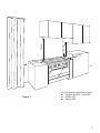
■ The cooker can be installed in a cabinet (Fig. 1).
■ The cooker must be installed no less than 50 mm away from any side wall which
exceed the height of the cooktop.
■ The appliance must be housed in heat resistant units.
■ The walls of the units must be capable of resisting temperatures of 75 °C above
room temperature.
■ Do not install the appliance near inammable materials (eg. curtains).
■ If you stand the cooker on a pedestal, make sure you provide safety measures
to keep it in place.

7
Figure 1
50 mm
500 mm
650 mm
450 mm
Cooker overall dimensions [mm]
■ height: min 900 - max 925
■ width: 900
■ depth: 600

8
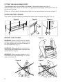
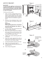
FITTING THE ADJUSTABLE FEET
The adjustable feet must be tted to the base of the cooker before use (g. 2).
Rest the rear of the cooker on a piece of the polystyrene packaging exposing the base for
the tting of the feet.
Fit the no. 4 (four) legs by screwing them tight into the support base as shown in gure 3.
LEVELLING THE COOKER
The cooker may be levelled by screwing the lower ends of the feet IN or OUT (g. 4).
Figure 3 Figure 4Figure 2
MOVING THE COOKER
WARNING: When raising cooker to upright
position always ensure two people carry
out this manoeuvre to prevent damage to
the adjustable feet (g. 5).
WARNING - Be carefull: Do not lift the co-
oker by the door handle when raising to the
upright position (g. 6).
WARNING: When moving cooker to its -
nal position DO NOT DRAG (g. 7). Lift feet
clear of oor (g. 5).
Figure 5
Figure 7Figure 6

9
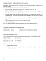
ANTI-TILT BRACKET
Important!
To restrain the appliance and prevent it
tipping accidentally, t a bracket to its
rear to x it securely to the wall. Make
sure you also t the supplied lock pin to
the anti-tilt bracket.
To t the anti-tilt bracket:
1. After you have located where the co-
oker is to be positioned, mark on the
wall the place where the two screws
of the anti-tilt bracket have to be tted.
Please follow the indications given in
g. 8.
2. Drill two 8 mm diameter holes in the
wall and insert the plastic plugs sup-
plied.
Important!
Before drilling the holes, check that
you will not damage any pipes or
electrical wires.
3. Loosely attach the anti-tilt bracket with
the two screws supplied.
4. Move the cooker to the wall and adjust
the height of the anti-tilt bracket so that
it can engage in the slot on the coo-
ker’s back, as shown in g. 8.
5. Tighten the screws attaching the anti-
tilt bracket.
6. Push the cooker against the wall so
that the anti-tilt bracket is fully inserted
in the slot on the cooker’s back.
7. Access the bracket and t the lock pin:
■ Open the pivoting panel (g. 9).
■ Fit the lock pin through the bracket, as
shown (g. 10).
■ Close the pivoting panel.
min 220
max 245
(depending on feet adjustment)
450
450
0
+ 25
900 mm
1
2
Pivoting
panel
Lock pin
correctly
fitted
Lock pin
Slot on the
cooker’s back
Cooker’s
back
Anti-tilt bracket
attached on the
rear wall
min 220
max 245
(depending on feet adjustment)
450
450
0
+ 25
900 mm
1
2
Pivoting
panel
Lock pin
correctly
fitted
Lock pin
Slot on the
cooker’s back
Cooker’s
back
Anti-tilt bracket
attached on the
rear wall
min 220
max 245
(depending on feet adjustment)
450
450
0
+ 25
900 mm
1
2
Pivoting
panel
Lock pin
correctly
fitted
Lock pin
Slot on the
cooker’s back
Cooker’s
back
Anti-tilt bracket
attached on the
rear wall
Figure 8
Figure 9
Figure 10

10
ELECTRICAL REQUIREMENTS
■ The appliance must be connected to the mains checking that the voltage correspon-
ds to the value given in the rating plate and that the electrical cable sections can
withstand the load specied on the plate.
■ A suitable disconnection switch must be incorporated in the permanent wiring, mounted
and positioned to comply with the local wiring rules and regulations. The switch must
be of an approved type installed in the xed wiring and provide a 3 mm air gap contact
separation in all poles in accordance with the local wiring rules.
In Australia and New Zealand, a switch of the approved type with a 3 mm air gap must
be installed in the active (phase) conductor of the xed wiring.
■ The switch must always be accessible.
■ The power supply cable must not touch the hot parts and must be positioned so that it
does not exceed 75°C above ambient.
■ To connect the cooker to the mains electricity supply, do not use adapters, reducers or
branching devices as they can cause overheating and burning.
■ This cooker must be connected to a suitable double pole control unit adjacent to the
cooker. No diversity can be applied to this control unit.
■ This cooker must be connected to electrical supply using V105 insulated cable.
In New Zealand, this appliance must be connected to the electrical supply using a
cable tted with an appropriately rated plug. The plug must be compatible with the
socket-outlet tted to the nal subcircuit in the xed wiring that is intended to supply
the appliance.
■ Once the appliance has been installed, the switch or socket must always be accessible.
■ If the supply cord is damaged it must be replaced by the manufacturer or it’s Service
Agent or a similarly qualied person in order to avoid a hazard.
N.B. The connection of the appliance to earth is mandatory.
If the installation requires alterations to the domestic electrical system call a qualied elec-
trician. He should also check that the domestic electrical system is suitable for the power
drawn by the appliance.
Replacing the power cord must be done by a qualied electrician in accordance with
the instructions supplied by the manufacturer and in compliance with established
electrical regulations.

11
max 290 mm
Dotted line
showing the
position of the
cooker when
installed
ELECTRIC CONNECTION
Area for ELECTRIC
connection
LOCATING THE AREA FOR ELECTRICAL CONNECTION
Figure 11

12
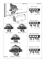
CONNECTION OF THE POWER SUPPLY CABLE
Important! This cooker must be connected to the electricity supply only by an au-
thorised person.
To connect the feeder cable to the cooker it is necessary to:
• Remove the two screws that hold shield “A” behind the cooker (g. 12).
• Open completely the cable clamp “D”.
• Fitted with a 6-pole terminal block, position the U bolts onto terminal block ‘B’ (g. 12)
according to the diagrams in gs. 13 - 14.
• Feed the supply cable through the cable clamp “D”. The supply cable must be of a
suitable size for the current requirements of the appliance; see the section “Feeder
cable section”.
• Connect the phase, neutral and earth wires to terminal “B” according to gures 13 and
14.
• Pull the feeder cable and block it with the cable clamp “D”.
• Re-mount shield “A”.
N.B. The earth conductor must be left about 3 cm longer than the others.
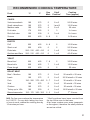
VOLTAGE AND POWER CONSUMPTION
230/400 V 3N~ 50 Hz 11800 W (51.30 A) (diversity not applied)
240/415 V 3N~ 50 Hz 12800 W (53.33 A) (diversity not applied)
FEEDER CABLE SECTION
This cooker must be connected to electrical supply using V105 insulated cable.
230 V~, 240 V~ 3 x 6 mm
2
(*)
230 V 3~, 240 V~ 4 x 4 mm
2
(*)
400 V 3N~, 415 V 3N~ 5 x 2,5 mm
2
(*)
400 V 2N~, 415 V 2N~ 4 x 4 mm
2
(*)
(*) Connection with wall box connection.
– Diversity factor applied.
– A diversity factor may be applied to the total loading of the appliance only by a
suitably qualied person.

13
2 3 4 51
2 3 4 51
2 3 4 51
2 3 4 51
PE
L1
L2
L3
230 V~
L1
L2
L3
N
PE
N(L
2
)
PE
L1
L1
L2
N
PE
400 V 3N~
400 V 2N~
230 V 3~
PE
123 4 5
N (L 2)L1
PE
123 4 5
PE
123 4 5
PE
123 4 5
L1 L2 L3
N
L1 L2 L3
N
L1 L2
230 V~
400 V 2N~
400 V 3N~
230 V 3~
A
D
B
Figure 14
Figure 12 Figure 13
230 V~, 240 V~
230 V~, 240 V~
230 V 3~, 240 V 3~
230 V 3~, 240 V 3~
400 V 3N~, 415 V 3N~
400 V 3N~, 415 V 3N~
400 V 2N~, 415 V 2N~
400 V 2N~, 415 V 2N~

14
H
S2
N/7
1
1a
L/8
PR
TL
T
M
5
432
1
F2 F3
F4 F5 F6
P3
4A
S2
4
P4
HS
2
4
4a
CR
1
4
3
2
5
P2
P1
P3
LF
C
G
S
V
TM
S1
F1
CF
S1
S2
4
P1
P2
PILOT
2
S1
S2
4
P1
P2
PILOT
2
S1
S2
4
P1
P2
PILOT
2
S1
S2
4
P1
P2
4a
2
S1
S2
4
P1
P2
4a
2
P2
S
2
4
P1
S
2
4
P5
S2
4
H
H
H
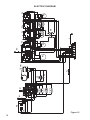
ELECTRIC DIAGRAM
Figure 15

15
ELECTRIC DIAGRAM KEY
P1/2/5 Hob single zones elements
P3 Hob double zone (oval) element
P4 Hob double zone element
F2/3/6 Energy regulators (single zones)
F4/5 Energy regulators (double zones)
F1 Oven switch
TM Oven thermostat
LF Oven lamp
PR Oven programmer
CF Cooling fan motor
V Oven fan motor
C Oven top element
G Oven grill element
S Oven bottom element
TL Thermal overload
S1 Thermostat pilot lamp
S2 Hob elements pilot lamp
CR Hob elements residual heat lamps
M Terminal block
T Earth connection

16
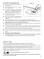
G
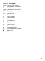
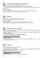
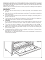
USING THE OVEN FOR THE FIRST
TIME
Operate as follows:
■ Slide in the wire racks on the oven
walls as in g. 16.
■ Slide in the grease lter on the back of
the oven as in g. 19.
■ Slide into the guides, the shelf and the
tray (g. 17).
The rack must be tted so that the sa-
fety notch, which stops it sliding out,
faces the inside of the oven; the guard
rail shall be at the back.
The oven tray must be correctly placed
on its wire shelf support (g. 18) then
inserted into the guides (g. 17). The
oven tray shelf support must be tted
so that the safety notch, which stops it
sliding out, faces the inside of the oven
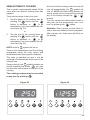
■ To eliminate traces of grease in manu-
facture it is necessary to pre-heat the
oven at the maximum temperature:
• For 60 minutes in the
position
and for another 15 minutes in the
position.
■ Slide off the wire racks.
■ Let the oven cool down, switch off the
electrical supply, then clean the inside
of the oven with a cloth soaked in wa-
ter and neutral detergent and dry tho-
roughly.
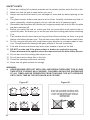
CAUTION:
■ This appliance must be used only for the task it has explicitly been designed for, that
is for domestic cooking of foodstuffs. Any other form of usage is to be considered as
inappropriate and therefore dangerous.
■ Do NOT place combustible materials or products on this appliance at any time.
USE AND CARE
Stop notch
Guard rail
Stop notch
Figure 16
Figure 17
Figure 18

17
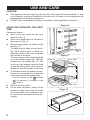
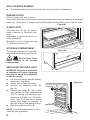
Figure 19
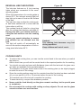
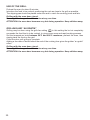
GREASE FILTER
■ A special screen is provided at the back of the oven to catch grease particles, mainly
when meat is being roasted.
■ Clean the lter after any cooking! The grease lter can be removed for cleaning and
should be washed regularly in hot soapy water (g. 19).
■ Always dry the lter properly before tting it back into the oven.
CAUTION: When baking pastry etc. this lter should be removed.

18
123456
9
10
78
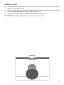
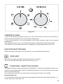
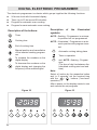
Controls description
1. Front right cooking zone control knob
2. Rear right cooking zone control knob
3. Central cooking zone control knob
4. Rear left cooking zone control knob
5. Front left cooking zone control knob
6. Oven temperature control knob
7. Oven function selector control knob
8. Electronic programmer
Pilot lamps:
9. Cooking zone/s ON indicator light
10. Oven temperature indicator light
Figure 20
Please note:
This appliance incorporates a safety cooling fan which you will hear operating whenever
the oven or grill are in use.
This fan is to reduce the external temperature of the appliance and cool the internal com-
ponents.
CONTROL PANEL

19
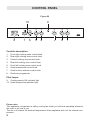
Attention:
Detach the appliance from the mains if the ceramic glass is cracked and contact the After-
Sales Service.
Metallic objects such as knives, forks, spoons and lids should not be placed on the hob
surface since they can get hot.
Figure 21
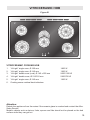
VITROCERAMIC COOKING HOB
1. “Hi-Light” single zone, Ø 180 mm 1800 W
2. “Hi-Light” single zone, Ø 145 mm 1200 W
3. “Hi-Light” double zone (oval), Ø 145 x 250 mm 2000/1100 W
4. “Hi-Light” double zone, Ø 210/120 mm 2200/750 W
5. “Hi-Light” single zone, Ø 145 mm 1200 W
6. Cooking zones residual heat indicators
OB
2
1
3
4
6
5
VITROCERAMIC HOB

20
Figure 22
Figure 23
HOW TO USE THE VITROCERAMIC HOB
The ceramic surface of the hob allows a fast transmission of heat in the vertical direction,
from the heating elements underneath the ceramic glass to the pans set on it.
The heat does not spread in a horizontal direction, so that the glass stays “cool” at only a
few centimeters from the cooking plate.
The cooking zones are shown by painted disks on the ceramic surface.
Before switching on the cooktop make sure that it is clean.
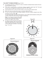
Important note:
The heating elements incorporate a thermolimiter that switches the element ON/OFF du-
ring all settings to protect the ceramic glass from overheating.
The use of incorrect pans and/or wrong pan positioning will cause the temperature limiter
to operate more frequently, resulting in a reduction of cooking performance.
The temperature limiter can be seen under the glass dissecting the element. This is not a
fault with the appliance.
“HI-LIGHT” SINGLE ZONES (g. 23)
■ The heating element is formed of a coil of resistant material which reaches the working
temperature quickly.
■ These zones are controlled by a continuous energy regulator switch (g. 22). The heat
intensity can be regulated continuously from “0” to “12” (max).
■ Check that the hob is clean and then switch on by turning the control knob.
■ When the hob is working, the power on indicator light will be on.
Page is loading ...
Page is loading ...
Page is loading ...
Page is loading ...
Page is loading ...
Page is loading ...
Page is loading ...
Page is loading ...
Page is loading ...
Page is loading ...
Page is loading ...
Page is loading ...
Page is loading ...
Page is loading ...
Page is loading ...
Page is loading ...
Page is loading ...
Page is loading ...
Page is loading ...
Page is loading ...
Page is loading ...
Page is loading ...
Page is loading ...
Page is loading ...
-
 1
1
-
 2
2
-
 3
3
-
 4
4
-
 5
5
-
 6
6
-
 7
7
-
 8
8
-
 9
9
-
 10
10
-
 11
11
-
 12
12
-
 13
13
-
 14
14
-
 15
15
-
 16
16
-
 17
17
-
 18
18
-
 19
19
-
 20
20
-
 21
21
-
 22
22
-
 23
23
-
 24
24
-
 25
25
-
 26
26
-
 27
27
-
 28
28
-
 29
29
-
 30
30
-
 31
31
-
 32
32
-
 33
33
-
 34
34
-
 35
35
-
 36
36
-
 37
37
-
 38
38
-
 39
39
-
 40
40
-
 41
41
-
 42
42
-
 43
43
-
 44
44


Ask a question and I''ll find the answer in the document
Finding information in a document is now easier with AI
Related papers
-
DeLonghi DE605MS User manual
-
-
-
DeLonghi DEP7410P User manual
-
-
DeLonghi DEL6038D User manual
-
-
-
DeLonghi DEFP907W Installation guide
-
Other documents
-
Indesit K3C36/G User manual
-
CDA DC930 Series User manual
-
Elba S 66 X 938 Instructions For Use Manual
-
Prestige PR60BIDOE Instructions For Use Manual
-
-
German pool SC610WH Specification
-
Samsung NZ64R3525CK User manual
-
KIC APCH GR Program Chart
-
Candy FCE943LX User manual
-
CDA SC510SS Specification