Page is loading ...

Instructions
Manual Electrostatic
PRO
™
Xs Waterborne
Air Spray Gun
Smart Model
247937
Standard Model
247936
#53
312900C
ENG
For use with conductive spray materials (waterborne and other materials
less than 1 megohm-cm). For professional use ONLY.
For use in Class I, Div. I hazardous locations using Group D spray materials.
For use in Group II, Zone 1 areas using Group IIA spray materials.
247936 Standard Model
247937 Smart Model
100 psi (0.7 MPa, 7 bar) Maximum Air Inlet Pressure
100 psi (0.7 MPa, 7 bar) Maximum Working Fluid Pressure
U.S. Patent Pending
Important Safety Instructions:
Read all warnings and instructions in this manual.
Save these instructions.
See page 2 for Table of Contents.
II 2 G EEx 0.24 mJ

2 312900C
Table of Contents
Warnings . . . . . . . . . . . . . . . . . . . . . . . . . . . . . . . . . 3
Warning Symbol . . . . . . . . . . . . . . . . . . . . . . . . . 3
Notice . . . . . . . . . . . . . . . . . . . . . . . . . . . . . . . . . 3
Overview . . . . . . . . . . . . . . . . . . . . . . . . . . . . . . . . . . 5
How the Electrostatic Air Spray Gun Works . . . . 5
Installation . . . . . . . . . . . . . . . . . . . . . . . . . . . . . . . . 9
Install the System . . . . . . . . . . . . . . . . . . . . . . . . 9
Warning Sign . . . . . . . . . . . . . . . . . . . . . . . . . . . . 9
Ventilate the Spray Booth . . . . . . . . . . . . . . . . . . 9
Connect the Air Line . . . . . . . . . . . . . . . . . . . . . 11
Connect the Charging Probe . . . . . . . . . . . . . . 11
Connect the Exhaust Tube . . . . . . . . . . . . . . . . 12
Connect the Fluid Line . . . . . . . . . . . . . . . . . . . 12
Filter the Fluid . . . . . . . . . . . . . . . . . . . . . . . . . . 12
Select a Fluid Nozzle and Air Cap . . . . . . . . . . 13
Grounding . . . . . . . . . . . . . . . . . . . . . . . . . . . . . 14
Check Electrical Grounding . . . . . . . . . . . . . . . . 15
Check Fluid Resistivity . . . . . . . . . . . . . . . . . . . 15
Check Fluid Viscosity . . . . . . . . . . . . . . . . . . . . 16
Prepare to Paint . . . . . . . . . . . . . . . . . . . . . . . . 16
Pressure Relief . . . . . . . . . . . . . . . . . . . . . . . . . . . 19
Shutdown . . . . . . . . . . . . . . . . . . . . . . . . . . . . . . . . 19
Maintenance . . . . . . . . . . . . . . . . . . . . . . . . . . . . . . 20
Electrical Troubleshooting . . . . . . . . . . . . . . . . . . 22
Electrical Tests . . . . . . . . . . . . . . . . . . . . . . . . . . . 23
Test Total Gun Resistance . . . . . . . . . . . . . . . . 23
Test Gun Resistance . . . . . . . . . . . . . . . . . . . . . 23
Test Charging Probe Resistance . . . . . . . . . . . . 23
Test Power Supply Resistance . . . . . . . . . . . . . 24
Test Barrel Resistance . . . . . . . . . . . . . . . . . . . 24
Spray Pattern Troubleshooting . . . . . . . . . . . . . . . 25
Gun Operation Troubleshooting . . . . . . . . . . . . . . 26
Gun Repair . . . . . . . . . . . . . . . . . . . . . . . . . . . . . . . 27
Prepare the Gun for Repair . . . . . . . . . . . . . . . . 27
Replace Air Cap/Nozzle . . . . . . . . . . . . . . . . . . 28
Replace Fluid Needle . . . . . . . . . . . . . . . . . . . . 28
Remove Fluid Packing . . . . . . . . . . . . . . . . . . . . 29
Repair Packing Rod . . . . . . . . . . . . . . . . . . . . . . 30
Remove Barrel . . . . . . . . . . . . . . . . . . . . . . . . . . 31
Install Barrel . . . . . . . . . . . . . . . . . . . . . . . . . . . . 31
Remove and Replace Power Supply . . . . . . . . . 32
Remove and Replace Turbine Alternator . . . . . . 33
Repair Fan Air Adjustment Valve . . . . . . . . . . . . 33
Repair Fluid Adjustment Valve . . . . . . . . . . . . . 34
Repair Air Valve . . . . . . . . . . . . . . . . . . . . . . . . . 34
Remove and Replace Atomizing
Air Restrictor Valve . . . . . . . . . . . . . . . . . . . 35
Repair ES ON/OFF Valve . . . . . . . . . . . . . . . . . 35
Parts . . . . . . . . . . . . . . . . . . . . . . . . . . . . . . . . . . . . 36
Accessories . . . . . . . . . . . . . . . . . . . . . . . . . . . . . . 41
Air Line Accessories . . . . . . . . . . . . . . . . . . . . . 41
Fluid Line Accessories . . . . . . . . . . . . . . . . . . . 41
Gun Accessories . . . . . . . . . . . . . . . . . . . . . . . . 42
Miscellaneous Accessories . . . . . . . . . . . . . . . . 42
Technical Data . . . . . . . . . . . . . . . . . . . . . . . . . . . . 43
Graco Warranty . . . . . . . . . . . . . . . . . . . . . . . . . . . 44
Graco Information . . . . . . . . . . . . . . . . . . . . . . . . . 44
Warnings
312900C 3
Warnings
Warning Symbol
This symbol alerts you to the possibility of serious injury
or death if you do not follow the instructions.
Notice
The following warnings are for the setup, use, grounding, maintenance, and repair of this equipment. The exclama-
tion point symbol alerts you to a general warning and the hazard symbol refers to procedure-specific risk. Refer back
to these warnings. Additional, product-specific warnings may be found throughout the body of this manual where
applicable.
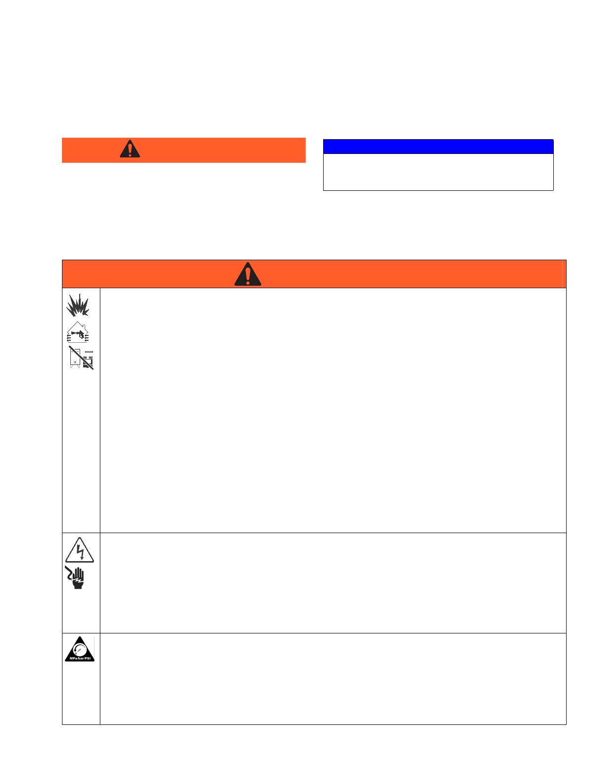
WARNING
NOTICE
A NOTICE alerts you to the possibility of damage to
or destruction of equipment if you do not follow the
instructions.
WARNINGWARNINGWARNING
WARNING
FIRE, EXPLOSION, AND ELECTRIC SHOCK HAZARD
Flammable fumes, such as solvent and paint fumes, in work area can ignite or explode. To help prevent fire
and explosion:
• Electrostatic equipment must be used only by trained, qualified personnel who understand the require-
ments of this manual.
• Ground equipment, personnel, object being sprayed, and conductive objects in work area. See
Grounding instructions.
• Only use grounded Graco conductive air supply hoses.
• Check gun and hose resistance and electrical grounding daily.
• Use and clean equipment only in well ventilated area.
• Interlock the gun air supply to prevent operation unless ventilating fans are on.
• Use cleaning solvents with highest possible flash point when flushing or cleaning equipment.
• Always turn the electrostatics off when flushing, cleaning or servicing equipment.
• If there is static sparking or you feel a shock, stop operation immediately. Do not use equipment until
you identify and correct the problem.
• Eliminate all ignition sources; such as pilot lights, cigarettes, portable electric lamps, and plastic drop
cloths (potential static arc).
• Do not plug or unplug power cords or turn lights on or off when flammable fumes are present.
• Keep work area free of debris, including solvent, rags and gasoline.
• Keep a working fire extinguisher in the work area.
ELECTRIC SHOCK HAZARD
This equipment must be grounded. Improper grounding, setup, or usage of the system can cause electric
shock.
• Turn off air supply before servicing equipment.
• All electrical wiring must be done by a qualified electrician and comply with all local codes and
regulations.
• Do not touch gun electrode when electrostatics are on.
• Do not expose to rain. Store indoors.
PRESSURIZED EQUIPMENT HAZARD
Fluid from the gun/dispense valve, leaks, or ruptured components can splash in the eyes or on skin and
cause serious injury.
• Follow Pressure Relief Procedure in this manual, when you stop spraying and before cleaning,
checking, or servicing equipment.
• Tighten all fluid connections before operating the equipment.
• Check hoses, tubes, and couplings daily. Replace worn or damaged parts immediately.
Warnings
4 312900C
WARNINGWARNINGWARNING
WARNING
EQUIPMENT MISUSE HAZARD
Misuse can cause death or serious injury.
• Do not operate the unit when fatigued or under the influence of drugs or alcohol.
• Do not exceed the maximum working pressure or temperature rating of the lowest rated system com-
ponent. See Technical Data in all equipment manuals.
• Do not leave the work area while equipment is energized or under pressure. Turn off all equipment and
follow the Pressure Relief Procedure in this manual when equipment is not in use.
• Check equipment daily. Repair or replace worn or damaged parts immediately with genuine manufac-
turer’s replacement parts only.
• Do not alter or modify equipment.
• Use equipment only for its intended purpose. Call your distributor for information.
• Route hoses and cables away from traffic areas, sharp edges, moving parts, and hot surfaces.
• Do not kink or over bend hoses or use hoses to pull equipment.
• Keep children and animals away from work area.
• Comply with all applicable safety regulations.
TOXIC FLUID OR FUMES HAZARD
Toxic fluids or fumes can cause serious injury or death if splashed in the eyes or on skin, inhaled, or swal-
lowed.
• Read MSDS’s to know the specific hazards of the fluids you are using.
• Store hazardous fluid in approved containers, and dispose of it according to applicable guidelines.
• Always wear impervious gloves when spraying or cleaning equipment.
• If this equipment is used with isocyanate material, see additional information on isocyanates in Isocya-
nate Conditions Section of this manual.
Overview
312900C 5
Overview
How the Electrostatic Air Spray Gun Works
The air hose supplies air to the spray gun. Part of the air
operates the turbine and the rest of the air atomizes the
fluid being sprayed. The turbine generates power, which
is converted by the power cartridge to supply high volt-
age current to the gun’s external charging probe.
The pump supplies fluid to the hose and gun, where the
fluid is atomized by the air cap and the atomized parti-
cles are electrostatically charged as they pass the
external charging probe. The charged fluid is attracted
to the grounded workpiece, wrapping around and
evenly coating all surfaces. The external charging
allows the fluid supply to remain grounded at all times
and therefore eliminate the need for an isolation sys-
tem.
MAX FLUID
WPR: 100 PSI
(7bar, 0.7 Mpa)
100
%
KV
Ma
0
HI
LO
ES
I O
ES
MAX AIR
WPR: 100 PSI
(7bar, 0.7 Mpa)
MAX FLUID WPR:
100 PSI (7bar, 0.7 Mpa)
MAX AIR WPR:
100 PSI (7bar, 0.7 Mpa)
To avoid shock or explosion
•Use properly grounded air hose
•Read instruction manual
I O
ES
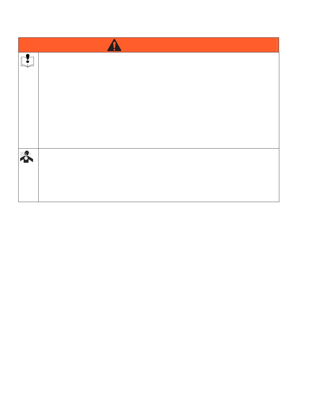
KEY
A Air swivel inlet page 6
B Fluid inlet page 6
C Turbine air exhaust page 6
D Air cap and nozzle page 6
E Fluid needle page 6
F Fluid adjustment page 7
G Fan air adjustment valve page 7
H Atomizing air restrictor valve page 7
I ES ON/OFF switch page 7
J ES indicator (247936 only) page 8
K Voltage/current display (247937 only) page 8
L ES HI/LO switch (247937 only) page 8
M LO voltage adjustment (247937 only) page 8
N External charging probe
A
BC
D
E
F
G
H
I
J
Standard Model
247936
L
K
M
F
G
I
Smart Model
247937
N
Smart Model
247937
ti12581
ti12582
ti12658

Overview
312900C 7
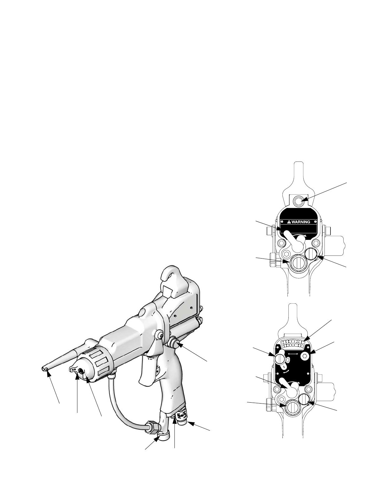
F. Fluid adjustment valve. Adjusts fluid needle travel.
Use only in low flow conditions, to reduce needle
wear.
G. Fan air adjustment valve. Adjusts fan size and
shape.
H. Atomizing air restrictor valve. Restricts atomizing
air flow. Replace with plug (included) if desired.
I. ES ON/OFF switch. Turns electrostatics ON (I) or
OFF (0).
MAX FLUID
WPR: 100 PSI
(7bar, 0.7 Mpa)
100
%
KV
Ma
0
HI
LO
ES
I O
ES
MAX AIR
WPR: 100 PSI
(7bar, 0.7 Mpa)
F
MAX FLUID
WPR: 100 PSI
(7bar, 0.7 Mpa)
100
%
KV
Ma
0
HI
LO
ES
I O
ES
MAX AIR
WPR: 100 PSI
(7bar, 0.7 Mpa)
G
ti1257a
I O
ES
H
MAX FLUID
WPR: 100 PSI
(7bar, 0.7 Mpa)
100
%
KV
Ma
0
HI
LO
ES
I O
ES
MAX AIR
WPR: 100 PSI
(7bar, 0.7 Mpa)
I
Overview
8 312900C
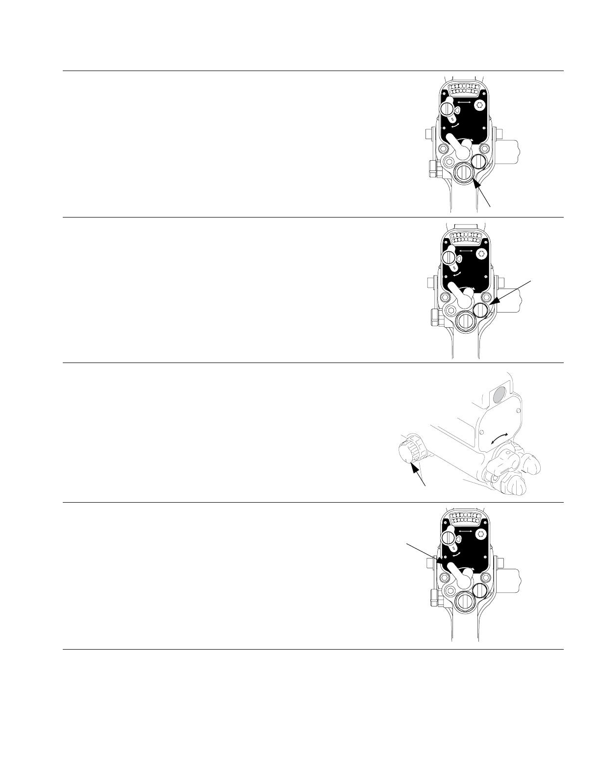
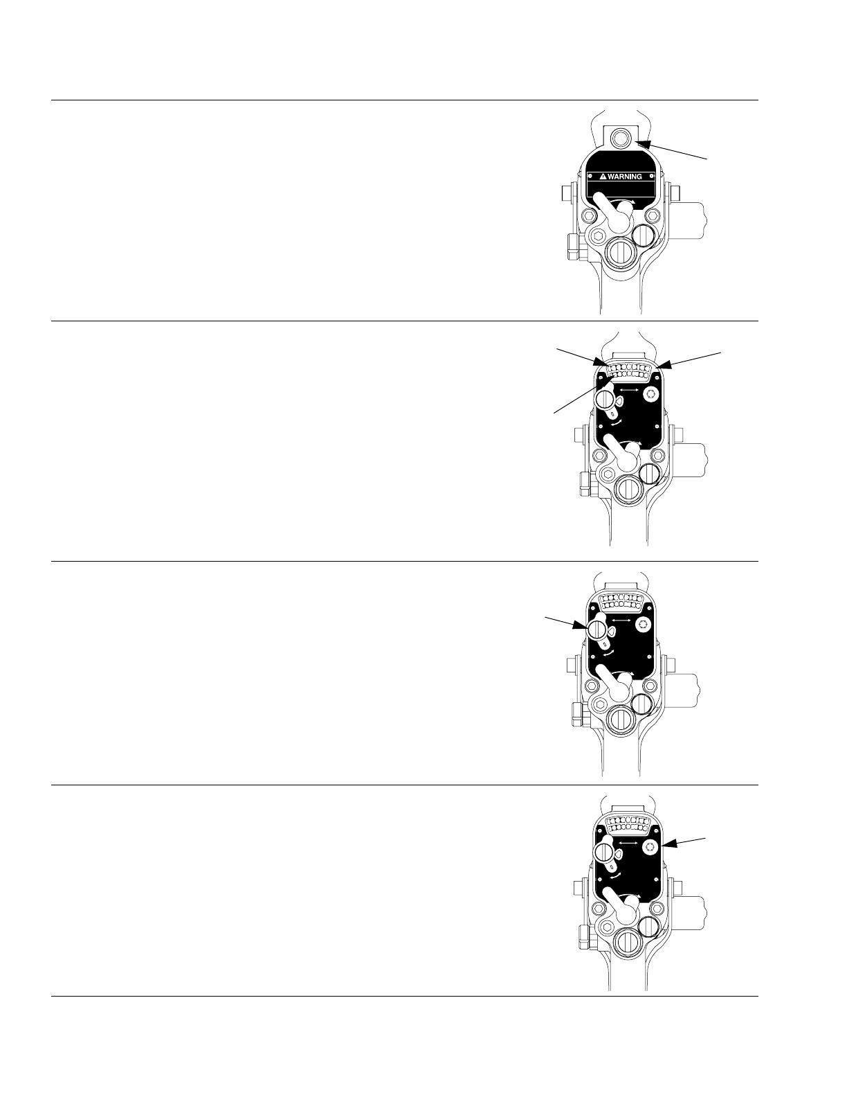
J. ES indicator (247936 only). Green when ES is ON
(I).
K. Voltage (247937 only). Shows voltage and
current.
Green/yellow=spray,
red=see Electrical Troubleshooting, page 22.
NOTE: Normal current draw for this model is higher
and the yellow current bar will be lit.
L. ES HI/LO switch (247937 only). Sets voltage to HI
or LO (factory settings).
M. LO voltage adjustment (247937 only). Remove
plug to adjust to 4 settings.
MAX FLUID WPR:
100 PSI (7bar, 0.7 Mpa)
MAX AIR WPR:
100 PSI (7bar, 0.7 Mpa)
To avoid shock or explosion
•Use properly grounded air hose
•Read instruction manual
I O
ES
J
ti12581
MAX FLUID
WPR: 100 PSI
(7bar, 0.7 Mpa)
100
%
KV
Ma
0
HI
LO
ES
I O
ES
MAX AIR
WPR: 100 PSI
(7bar, 0.7 Mpa)
K
Voltage
Current
ti12582
MAX FLUID
WPR: 100 PSI
(7bar, 0.7 Mpa)
100
%
KV
Ma
0
HI
LO
ES
I O
ES
MAX AIR
WPR: 100 PSI
(7bar, 0.7 Mpa)
L
ti12582
MAX FLUID
WPR: 100 PSI
(7bar, 0.7 Mpa)
100
%
KV
Ma
0
HI
LO
ES
I O
ES
MAX AIR
WPR: 100 PSI
(7bar, 0.7 Mpa)
M
ti12582
Installation
312900C 9
Installation
Install the System
FIG. 1. shows a typical electrostatic air spray system. It
is not an actual system design. For assistance in
designing a system to suit your particular needs, contact
your Graco distributor.
Warning Sign
Mount warning signs in the spray area where they can
easily be seen and read by all operators. An English
Warning Sign is provided with the gun.
Ventilate the Spray Booth
Electrically interlock the gun air supply with the ventila-
tors to prevent gun operation without ventilating fans
operating. Check and follow all National, State, and
Local codes regarding air exhaust velocity require-
ments.
High velocity air exhaust will decrease the operating effi-
ciency of the electrostatic system. Air exhaust velocity of
100 ft/min (31 linear meters/minute) should be sufficient.
Installing and servicing this equipment requires
access to parts which may cause electric shock or
other serious injury if work is not performed properly.
• Do not install or service this equipment unless you
are trained and qualified.
• Be sure your installation complies with National,
State and Local codes for the installation of elec-
trical apparatus in a Class I, Div. I, Group D or a
Group II, Category 2G Hazardous Location.
• Comply with all applicable local, state, and
national fire, electrical, and other safety regula-
tions.
Provide fresh air ventilation to avoid the buildup of
flammable or toxic vapors when spraying, flushing,
or cleaning the gun. Do not operate the gun unless
ventilation fans are operating.

Installation
10 312900C
Fig. 1. Typical Installation
Key
a
b‡
c‡d
‡e
f
g
h
k
m
n
o
‡r
s
u‡
v
w
c‡
g
q‡
t
p
l
j‡
ES ON/OFF valve:
I is ON, O is OFF
ti12721
ti1498ax
a Main Air Supply Line
b‡ Ventilation Fan Interlock Solenoid Valve
c‡ Main Air Supply Shutoff Valve (bleed-type)
d Pump Air Line Filter/Water Separator
e‡ Pump Air Supply Shutoff Valve (bleed-type)
f Air Line Lubricator
g Air Pressure Regulator
hPump
j‡ Pump Ground Wire
k Fluid Filter
l Fluid Supply Line Shutoff Valve
m Fluid Pressure Regulator
n Fluid Supply Line
o Gun Air Line Filter/Water Separator
p Gun Air Supply Line Shutoff Valve (bleed-type)
q‡ Air Hose Ground Wire
r‡ Graco Grounded Air Hose
s Electrostatic Air Spray Gun
t Air Line Drain Valve
u‡ Fluid Drain Valve
vGun Air Inlet
w Gun Fluid Inlet
‡ These items are required for proper operation
and must be purchased separately.
NOTE: Solenoid valve (b) is not offered as a
Graco accessory.

Installation
312900C 11
Connect the Air Line
1. Connect the Graco Grounded Air Supply Hose (R)
between the air supply line and the gun's air inlet (V)
(F
IG. 2). The gun air inlet fitting has a left-hand
thread. Connect the air supply hose ground wire (Q)
to a true earth ground.
2. Install an air line filter/water separator (O) on the
gun air line to ensure a dry, clean air supply to the
gun. Dirt and moisture can ruin the appearance of
your finished workpiece and can cause the gun to
malfunction.
3. Install a bleed-type air regulator (G) on the pump
and gun air supply lines to control air pressure to the
pump and gun.
4. Install a bleed-type air valve (E) on the pump air line
to shut off air to the pump. Install an additional
bleed-type air valve (C) on the main air line (A) to
isolate the accessories for servicing.
5. Install an air shutoff valve (P) on each gun air supply
line to shut off air to the gun(s).
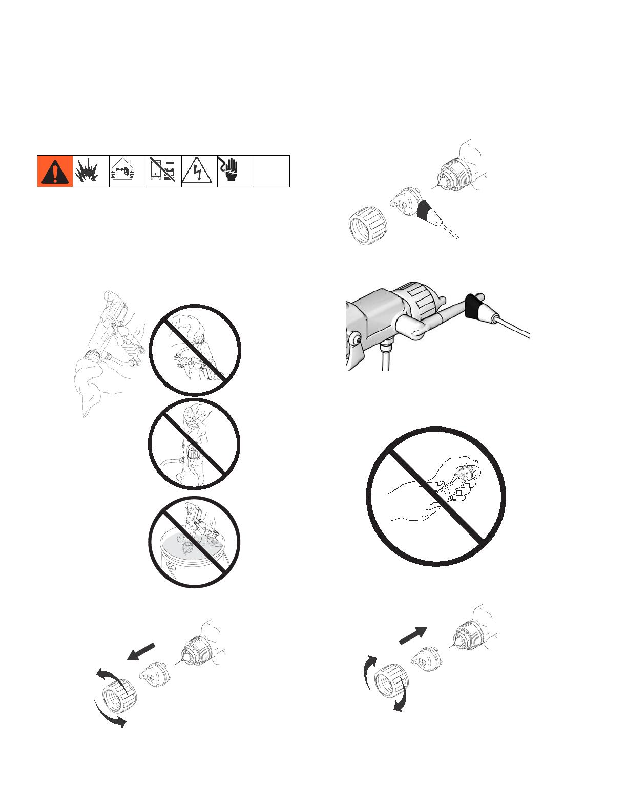
Connect the Charging Probe
1. Apply dielectric grease to probe socket.
2. Press electrode on in Connect/Disconnect position
shown in F
IG. 4.
3. Rotate electrode to spray position.
F
IG. 4
To reduce the risk of electric shock or other serious
injury, the air supply hose must be electrically con-
nected to a true earth ground. Use only Graco
Grounded Air Supply Hose.
F
IG. 2
The bleed-type air valve (E) is required in your sys-
tem to relieve air trapped between the valve and the
pump after the air regulator is shut off. Trapped air
can cause the pump to cycle unexpectedly, which
can result in serious injury, including splashing fluid
in the eyes or on the skin.
ti1259a
R
V
Q
To air supply
ti1259
FIG. 3
NOTICE
The external charging probe rotates easily. Do not
press too hard when rotating it or it could be dam-
aged.
NOTICE
For proper performance, do not operate electro-
statics if the charging probe is not in spray position.
Probe
Socket
ti12722
ti1933a
Connect/Disconnect
Position
Connect the Charging Electrode
Position
Spray

Installation
12 312900C
Connect the Exhaust Tube
Press the exhaust tube (38) onto the barbed adapter on
the bottom of the gun handle. Secure the tube with the
clamp (39) (F
IG. 5).
Connect the Fluid Line
1. Before connecting the fluid line (N), blow it out with
air and flush it with solvent. Use solvent compatible
with the fluid to be sprayed.
2. Install a fluid regulator (M) on the fluid line to control
fluid pressure to the gun.
3. Install a fluid filter (K) and drain valve (U) at the
pump outlet.
4. Connect the fluid line to the 3/8 npsm gun fluid inlet
(W) (F
IG. 6).
5. Before running any paint through the spray gun,
flush it with a compatible solvent.
Filter the Fluid
Install a fluid filter (K) to remove particles and sediment
that could clog the spray nozzle.
F
IG. 5
The fluid drain valve (U) is required in your system to
assist in relieving fluid pressure in the displacement
pump, hose, and gun. Triggering the gun to relieve
pressure may not be sufficient. Install a drain valve
close to the pump's fluid outlet. The drain valve
reduces the risk of serious injury, including splashing
in the eyes or on the skin.
ti1275a
Barbed adapter
39
38
F
IG. 6
ti1277a
N
W
ti1277
Installation
312900C 13
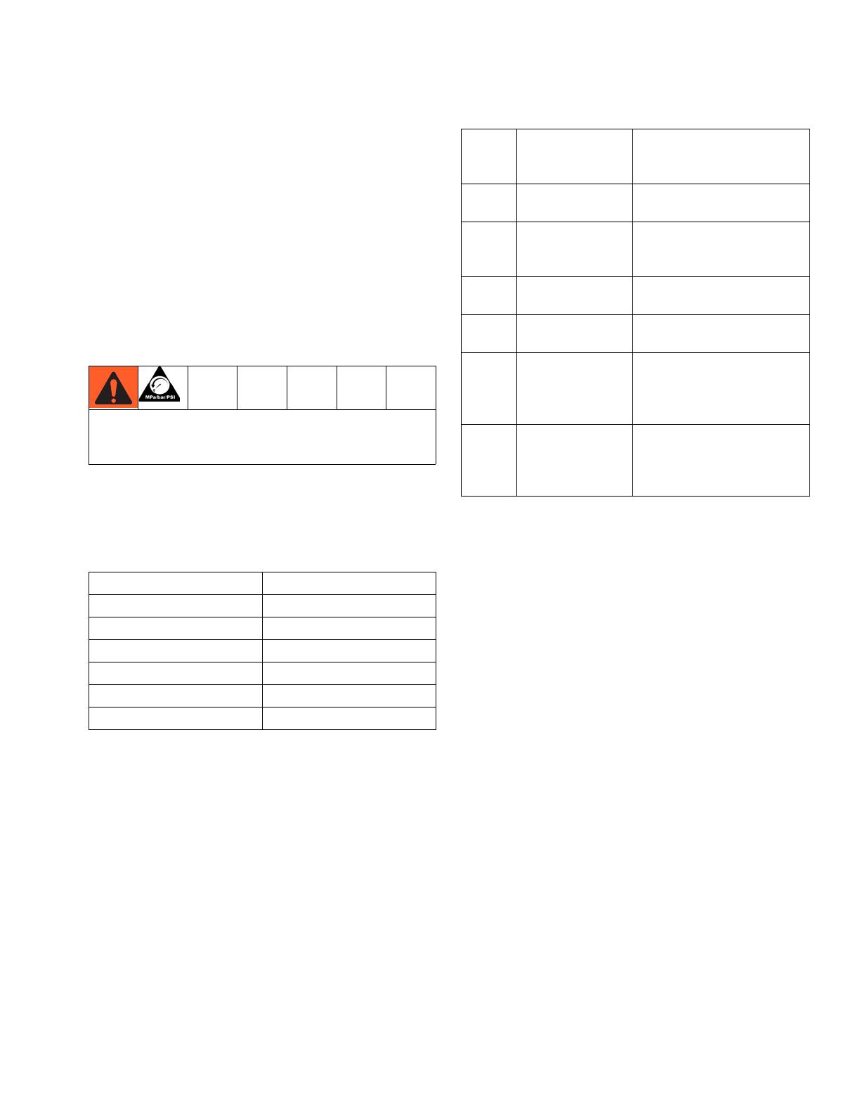
Select a Fluid Nozzle and Air
Cap
The gun is supplied with Part No. 197266 Nozzle and
24A276 Air Cap. If you require a different size, refer to
Table 1 and Table 2 , and instruction manual 309419, or
consult with your Graco distributor. See Replace Air
Cap/Nozzle on page 28.
A wide pattern kit (P/N 24A431) is included with the gun
and if installed, will provide more fan air for wider spray
patterns. (If pattern becomes split, use the fan air valve
to reduce the amount of fan air.)
NOTE: Due to the larger needle diameter, use a nozzle
one size larger than you would use with a standard Pro
Xs gun (i.e., 1.5 mm = 1.2 mm flow area).
* Glass-reinforced acetal construction.
*Also available in the following colors:
24A376 - gray
24A277 - red
24A278 - green
To reduce the risk of an injury, follow the Pressure
Relief procedure on page 19 before removing or
installing a fluid nozzle and/or air cap.
Table 1: Fluid Nozzles
Part No. Orifice Size
197265 1.2 mm (.047 in.)
197266 1.5 mm (.055 in.)
197267 1.8 mm (.070 in.)
249922* 1.2 mm (.047 in.)
249923* 1.5 mm (.055 in.)
249924* 1.8 mm (.070 in.)
Table 2: Air Caps
Part No.
Pattern Shape
and Length in.
(mm)
Recommended Fluids and
Production Rates
24A438
Round end;
15-17 (381-432)
Light to medium viscosity.
Up to 15 oz/min (450 cc/min)
24A279
Round end;
14-16 (356-406)
Medium to high viscosity and
high solids.
Up to 15 oz/min (450 cc/min)
24A276*
Tapered end;
17-19 (432-483)
Light to medium viscosity.
Up to 15 oz/min (450 cc/min)
24A274
Tapered end;
12-14 (305-356)
Light to medium viscosity.
Up to 15 oz/min (450 cc/min)
24A439
Round end;
11-13 (279-330)
Medium to high viscosity and
high solids.
Up to 15 oz/min (450 cc/min)
For use with 2.0 mm nozzle.
24A275
Tapered end;
14-16 (356-406)
Light to medium viscosity and
high solids.
Aerospace coatings.
Up to 25 oz/min (750 cc/min).
Installation
14 312900C
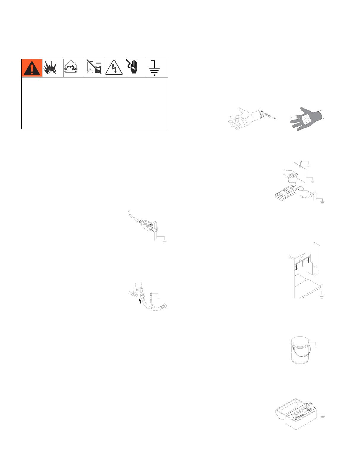
Grounding
The following are minimum grounding requirements for
a basic electrostatic system. Your system may include
other equipment or objects which must be grounded.
Check your local electrical code for detailed grounding
instructions. Your system must be connected to a true
earth ground.
• Pump: ground the pump by connecting a ground
wire and clamp as described in your separate pump
instruction manual.
• Electrostatic Air Spray Gun: ground the gun by con-
necting the Graco Grounded Air Hose and connect-
ing the air hose ground wire to a true earth ground.
See Check Electrical Grounding, page 15.
• Air compressors: ground the equipment according
to the manufacturer's recommendations.
• All air and fluid lines must be properly grounded.
Use only grounded hoses with a maximum of 100
feet (30.5 m) combined hose length to ensure
grounding continuity.
• All persons entering the spray area: shoes must
have conductive soles, such as leather, or personal
grounding straps must be worn. Do not wear shoes
with non-conductive soles such as rubber or plastic.
If gloves are necessary, wear the conductive gloves
that are supplied with the gun. If non-Graco gloves
are worn, cut off fingers or palm area of gloves to
ensure your hand contacts the grounded gun han-
dle.
• Object being sprayed: keep the workpiece hangers
clean and grounded at all times. Resistance must
not exceed 1 megohm.
• The floor of the spray area: must be electrically con-
ductive and grounded. Do not cover the floor with
cardboard or any non-conductive material which
would interrupt grounding continuity.
• Flammable liquids in the spray area: must be kept in
approved, grounded containers. Do not use plastic
containers. Do not store more than the quantity
needed for one shift.
• All electrically conductive objects or devices in the
spray area: including fluid containers and wash
cans, must be properly grounded.
Fire, Explosion, and Electric Shock Hazard
When operating the electrostatic gun, any ungrounded
objects in the spray area (people, containers, tools,
etc.) can become electrically charged. Improper
grounding can result in static sparking, which can
cause a fire, explosion, or electric shock. Follow the
grounding instructions below.
ti1259a

Installation
312900C 15
Check Electrical Grounding
1. Have a qualified electrician check the electrical
grounding continuity of the spray gun and air hose.
2. Turn the ES ON/OFF valve OFF.
3. Turn off the air and fluid supply to the gun. The fluid
hose must not have any fluid in it.
4. Make sure the grounded air hose (R) is connected
and the hose ground wire is connected to a true
earth ground.
5. Measure the resistance between the gun handle
(BB) and a true earth ground (CC). Use an applied
voltage of 500 minimum to 1000 volts maximum.
The resistance should not exceed 1 megohm. See
F
IG. 7.
6. If the resistance is greater than 1 megohm, check
the tightness of the ground connections and be sure
the air hose ground wire is connected to a true earth
ground. If the resistance is still too high, replace the
air hose.
Fig. 7. Check Gun Grounding
Check Fluid Resistivity
Graco Part No. 722886 Resistance Meter and 722860
Probe are available as accessories to check that the
resistivity of the fluid being sprayed meets the require-
ments of an electrostatic air spray system.
Follow the instructions included with the meter and
probe. If the material is above 1 megohm-cm, then a Pro
Xs3 HC gun may be a better option. The Pro Xs WB gun
is intended to spray very conductive waterborne materi-
als and other materials less than 1 megohm-cm.
Fire, Explosion, and Electric Shock Hazard
Megohmmeter Part No. 241079 (AA-see F
IG. 7.) is not
approved for use in a hazardous area. To reduce the
risk of sparking, do not use the megohmmeter to
check electrical grounding unless:
• The gun has been removed from the hazardous
area;
• Or all spraying devices in the hazardous area are
turned off, ventilation fans in the hazardous area are
operating, and there are no flammable vapors in the
area (such as open solvent containers or fumes
from spraying).
Failure to follow this warning could cause fire, explo-
sion, and electric shock and result in serious injury
and property damage.
ti1259a
Fire, Explosion, and Electric Shock Hazard
Check the fluid resistivity in a non-hazardous area
only. Resistance Meter 722886 and Probe 722860 are
not approved for use in a hazardous area.
Failure to follow this warning could cause fire, explo-
sion, or electric shock and result in serious injury and
property damage.
ti1274a
AA
BB
CC

Installation
16 312900C
Check Fluid Viscosity
To check fluid viscosity you will need:
• a viscosity cup
• a stopwatch.
1. Completely submerge the viscosity cup in the fluid.
Lift the cup out quickly, starting the stopwatch as
soon as the cup is completely removed.
2. Watch the stream of fluid coming from the bottom of
the cup. As soon as there is a break in the stream,
shut off the stopwatch.
3. Record the fluid type, elapsed time, and size of the
viscosity cup.
4. If the viscosity is too high or too low, contact the
material supplier. Adjust as necessary.
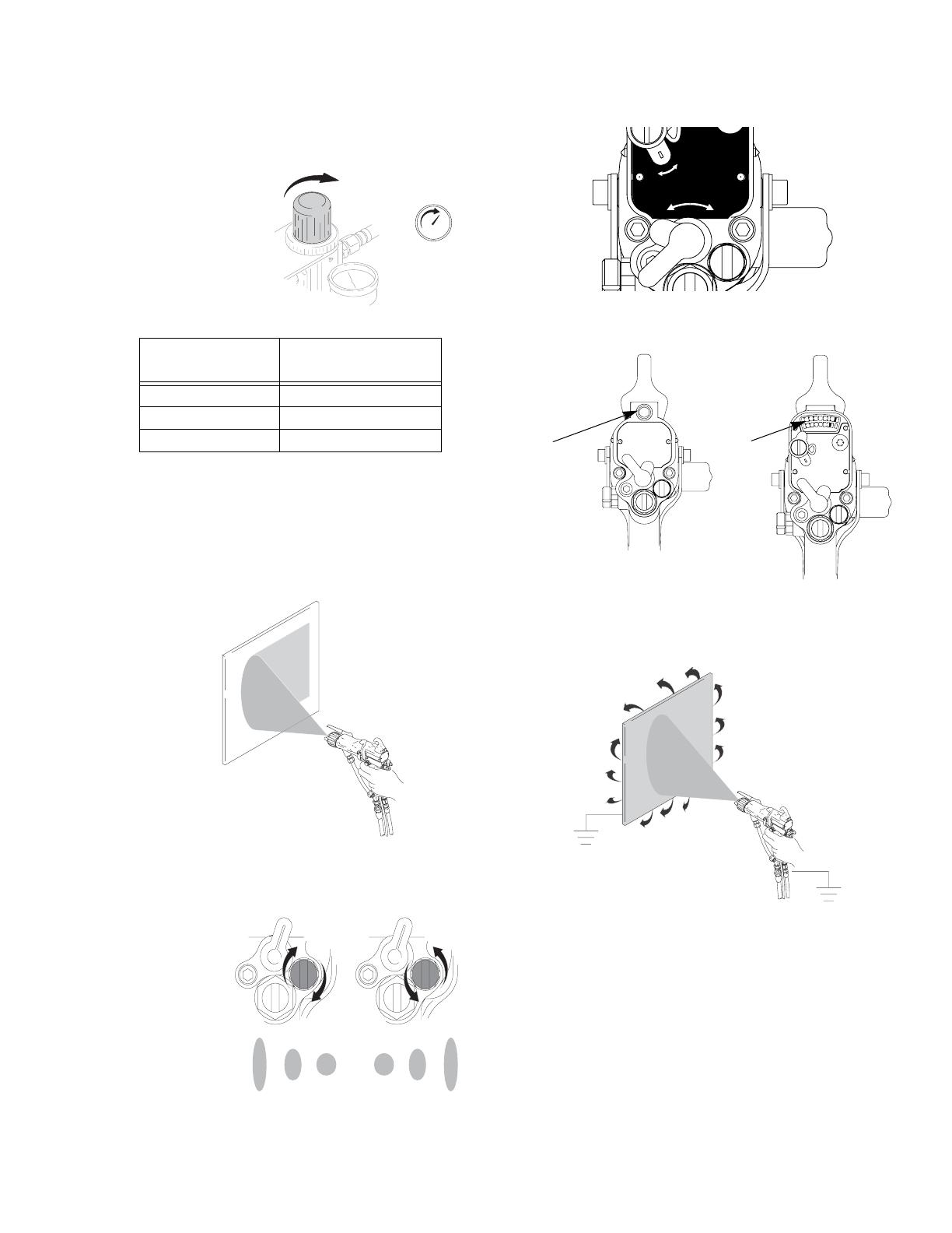
Prepare to Paint
1. Position air cap.
2. Fully open fan air adjustment valve.
3. Fully open fluid adjustment valve.
4. Fully open atomizing air restrictor valve.
5. Check that ES ON/OFF switch is OFF (O).
6. Start pump. Adjust fluid regulator until stream from
gun travels 8-12 in. (200-300 mm) before falling off.
Typically, if fluid pressure is below 5 psi (.04 MPa,
0.4 bar) or above 20 psi (0.14 MPa, 1.4 bar), a
change of nozzle size is recommended.
To avoid shock or explosion
•Use properly grounded air hose
•Read instruction manual
I O
ES
To avoid shock or explosion
•Use properly grounded air hose
•Read instruction manual
I O
ES
ti1272a
LO
ES
I O
ES
MAX AIR
WPR: 100 PSI
(7bar, 0.7 Mpa)
NOTE: This illustration
shows the switch in the
ON (I) position to view
I and O indicators.
ti12723
8-12 in.
(200-300 mm)
ti12684
Installation
312900C 17
7. Set gun air regulator to deliver minimum 40 psi (0.28
MPa, 2.8 bar) at gun when triggered, for maximum
transfer efficiency. See table at right.
8. Spray test pattern. Check atomization. If over-atomi-
zation occurs at minimum pressure, adjust restrictor
valve. If atomization is inadequate, increase air
pressure.
9. Adjust fan air adjustment valve: clockwise for a
shorter pattern, counterclockwise for wider pattern.
10. Turn ES ON/OFF switch ON (I).
11. Check that ES indicator or display is lit. If not,
see Electrical Troubleshooting, page 22.
12. Spray test piece. Examine edges for coverage. If
wrap is poor, see Spray Pattern Troubleshooting,
page 25.
TI1281A
Air Hose* Length
ft (m)
Regulator Setting**
psi (MPa, bar)
15 (4.6) 50 (0.35, 3.5)
25 (7.6) 60 (0.42, 4.2)
50 (15.3) 75 (0.52, 5.2)
* 5/16 in. (8 mm) diameter/8 mm (5/16 in.)
**Gun triggered
ti1282b
ti1283
a
MAX FLUID
WPR: 100 PSI
(7bar, 0.7 Mpa)
HI
LO
ES
I O
ES
MAX AIR
WPR: 100 PSI
(7bar, 0.7 Mpa)
ti12732
Standard Model
247936
Smart Model
247937
ES
indicator
ES
display
ti1285b

Installation
18 312900C
Flush
1. Turn ES ON/OFF switch OFF (O).
2. Relieve pressure, page 19.
3. Change fluid source to solvent, or disconnect fluid
line and connect solvent supply line to gun.
4. Point gun into grounded metal pail. Flush until clean
solvent flows from gun.
5. Relieve pressure, page 19.
6. Hang gun from hook. Nozzle must point down.
Fire, Explosion, and Electric Shock Hazard
Read Fire and Explosion, and Electric Shock
Hazards, page 3. Follow steps 1-6 below to flush the
gun when using gun first time, changing colors, before
fluid dries, at end of day, and before storing gun.
NOTICE
This gun has nylon components which will be dam-
aged if you use methylene chloride as a flushing or
cleaning solvent.
ti12724_x2
ti1934
ti1287a
ti1934
ti1934
ti12718

Pressure Relief
312900C 19
Pressure Relief
1. Turn the ES ON/OFF valve OFF.
2. Turn off the air bleed valves to the fluid source and
to the gun.
3. Trigger the gun into a grounded metal waste con-
tainer to relieve the fluid pressure.
4. Open the pump drain valve, having a waste con-
tainer ready to catch the drainage. Leave the pump
drain valve open until you are ready to spray again.
5. If the nozzle or hose is completely clogged or pres-
sure is not fully relieved, slowly loosen the hose end
coupling. Now clear the nozzle or hose.
Shutdown
Follow these steps at end of workshift and before clean-
ing, checking, or repairing equipment
1. Flush, page 18.
2. Hang gun from hook. Nozzle must point down.
Pressurized Equipment Hazard
The system pressure must be manually relieved to
prevent the system from starting or spraying acciden-
tally. To reduce the risk of an injury from electric shock,
accidental spray from the gun, splashing fluid, or mov-
ing parts, follow the Pressure Relief Procedure
whenever you:
• are instructed to relieve the pressure
• stop spraying
• check or service any of the system equipment
ti12724_x2
ti1289
ti1934
ti1290a
ti1298a
ti1298
ti1934
ti12718
Maintenance
20 312900C
Maintenance
Clean Gun Daily
1. Flush, page 18.
2.
a. Clean outside of gun with non-conductive,
compatible solvent. Point gun down.
b. Use soft, damp cloth.
c. Do not immerse gun.
3. Remove air cap.
4. Clean air cap, retaining ring, and nozzle with soft
brush and non-conductive, compatible solvent.
5. Clean probe with soft brush and compatible solvent.
6. Use toothpick or other soft tool to clean air cap
holes. Do not use metal tools.
7. Reinstall air cap. Tighten securely.
ti1292a
ti1293a
ti1294a
ti1295a
ti1296
ti1297a
ti12716
ti1299a
/